2007 SUZUKI SWIFT Valve clearance
[x] Cancel search: Valve clearancePage 102 of 1496
Downloaded from www.Manualslib.com manuals search engine 1A-52 Engine General Information and Diagnosis:
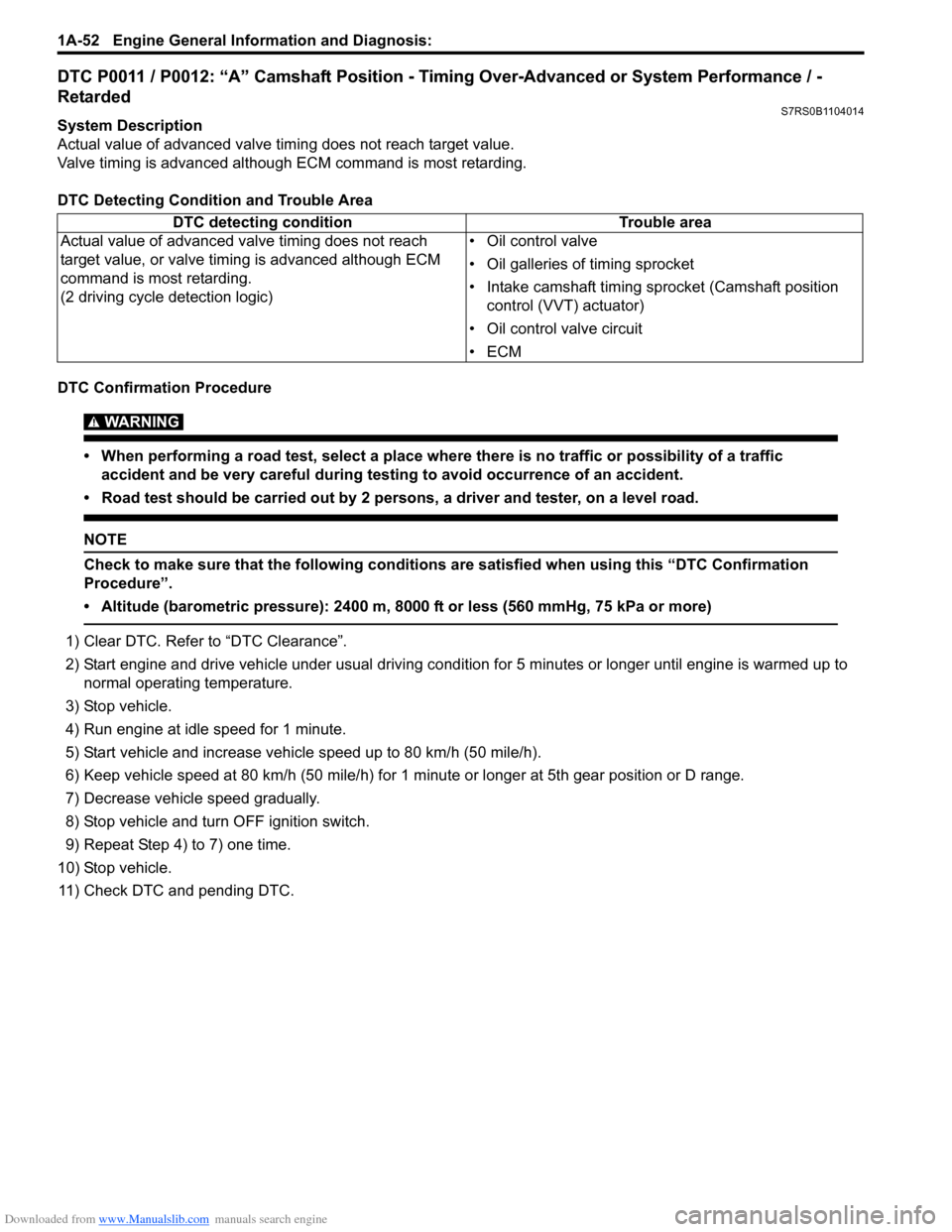
DTC P0011 / P0012: “A” Camshaft Position - Timing Over-Advanced or System Performance / -
Retarded
S7RS0B1104014
System Description
Actual value of advanced valve timing does not reach target value.
Valve timing is advanced although ECM command is most retarding.
DTC Detecting Condition and Trouble Area
DTC Confirmation Procedure
WARNING!
• When performing a road test, select a place where there is no traffic or possibility of a traffic accident and be very careful during testing to avoid occurrence of an accident.
• Road test should be carried out by 2 persons, a driver and tester, on a level road.
NOTE
Check to make sure that the following conditions are satisfied when using this “DTC Confirmation
Procedure”.
• Altitude (barometric pressure): 2400 m, 8000 ft or less (560 mmHg, 75 kPa or more)
1) Clear DTC. Refer to “DTC Clearance”.
2) Start engine and drive vehicle under usual driving condition for 5 minutes or longer until engine is warmed up to normal operating temperature.
3) Stop vehicle.
4) Run engine at idle speed for 1 minute.
5) Start vehicle and increase vehicle speed up to 80 km/h (50 mile/h).
6) Keep vehicle speed at 80 km/h (50 mile/h) for 1 minute or longer at 5th gear position or D range.
7) Decrease vehicle speed gradually.
8) Stop vehicle and turn OFF ignition switch.
9) Repeat Step 4) to 7) one time.
10) Stop vehicle. 11) Check DTC and pending DTC. DTC detecting condition
Trouble area
Actual value of advanced valve timing does not reach
target value, or valve timi ng is advanced although ECM
command is most retarding.
(2 driving cycle detection logic) • Oil control valve
• Oil galleries of timing sprocket
• Intake camshaft timing sprocket (Camshaft position
control (VVT) actuator)
• Oil control valve circuit
•ECM
Page 157 of 1496
Downloaded from www.Manualslib.com manuals search engine Engine General Information and Diagnosis: 1A-107
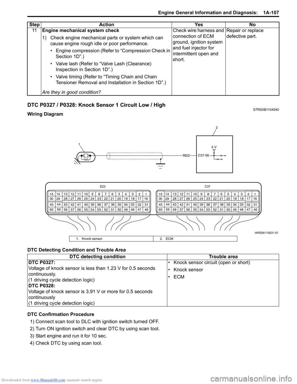
DTC P0327 / P0328: Knock Sensor 1 Circuit Low / HighS7RS0B1104040
Wiring Diagram
DTC Detecting Condition and Trouble Area
DTC Confirmation Procedure1) Connect scan tool to DLC with ignition switch turned OFF.
2) Turn ON ignition switch and clear DTC by using scan tool.
3) Start engine and run it for 10 sec.
4) Check DTC by using scan tool. 11
Engine mechanical system check
1) Check engine mechanical parts or system which can
cause engine rough idle or poor performance.
• Engine compression (Refer to “Compression Check in Section 1D”.)
• Valve lash (Refer to “Valve Lash (Clearance) Inspection in Section 1D”.)
• Valve timing (Refer to “Timing Chain and Chain Tensioner Removal and Installation in Section 1D”.)
Are they in good condition? Check wire harness and
connection of ECM
ground, ignition system
and fuel injector for
intermittent open and
short.
Repair or replace
defective part.
Step
Action YesNo
E23 C37
34
1819
567
1011
17
20
47 46
495051
2122
52 16
25 9
24
14
29
55
57 54 53
59
60 58 2
262728
15
30
56 4832 31
34353637
40
42 39 38
44
45 43 41 331
1213
238
34
1819
567
1011
17
20
47 46
495051
2122
52 16
25 9
24
14
29
55
57 54 53
59
60 58 2
262728
15
30
56 4832 31
34353637
40
42 39 38
44
45 43 41 331
1213
238
1 2
REDC37-56
5 V
I4RS0A110031-01
1. Knock sensor
2. ECM
DTC detecting condition Trouble area
DTC P0327:
Voltage of knock sensor is less than 1.23 V for 0.5 seconds
continuously.
(1 driving cycle detection logic)
DTC P0328:
Voltage of knock sensor is 3.91 V or more for 0.5 seconds
continuously
(1 driving cycle detection logic) • Knock sensor circuit (open or short)
• Knock sensor
•ECM
Page 291 of 1496
Downloaded from www.Manualslib.com manuals search engine Engine Mechanical: 1D-6
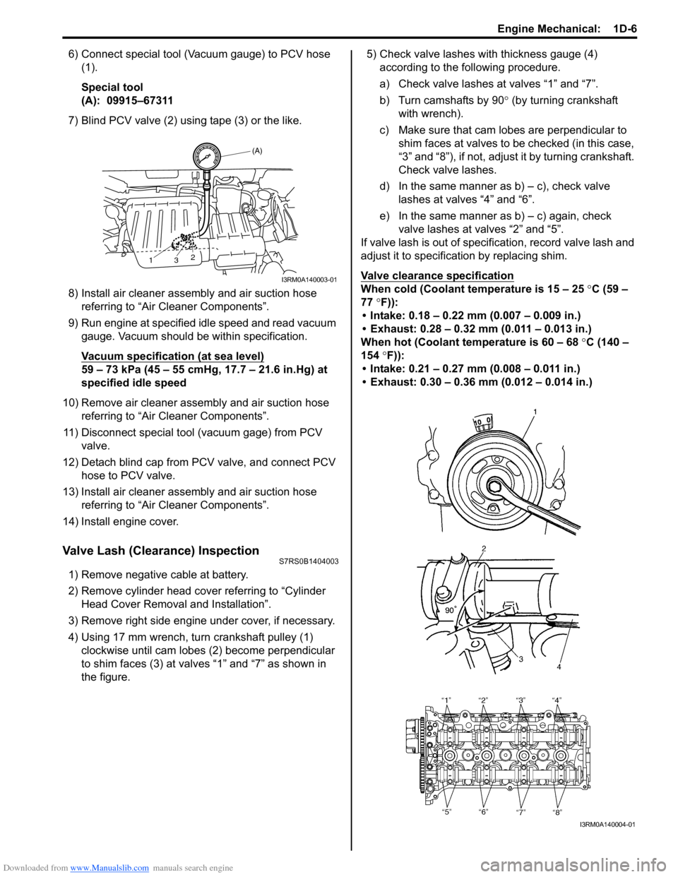
6) Connect special tool (Vacuum gauge) to PCV hose (1).
Special tool
(A): 09915–67311
7) Blind PCV valve (2) using tape (3) or the like.
8) Install air cleaner assembly and air suction hose referring to “Air Cleaner Components”.
9) Run engine at specified idle speed and read vacuum gauge. Vacuum should be within specification.
Vacuum specification (at sea level)
59 – 73 kPa (45 – 55 cmHg, 17.7 – 21.6 in.Hg) at
specified idle speed
10) Remove air cleaner assembly and air suction hose referring to “Air Cleaner Components”.
11) Disconnect special tool (vacuum gage) from PCV valve.
12) Detach blind cap from PCV valve, and connect PCV hose to PCV valve.
13) Install air cleaner assembly and air suction hose referring to “Air Cleaner Components”.
14) Install engine cover.
Valve Lash (Clearance) InspectionS7RS0B1404003
1) Remove negative cable at battery.
2) Remove cylinder head cover referring to “Cylinder Head Cover Removal and Installation”.
3) Remove right side engine under cover, if necessary.
4) Using 17 mm wrench, turn crankshaft pulley (1) clockwise until cam lobes (2) become perpendicular
to shim faces (3) at valves “1” and “7” as shown in
the figure. 5) Check valve lashes with thickness gauge (4)
according to the following procedure.
a) Check valve lashes at valves “1” and “7”.
b) Turn camshafts by 90 ° (by turning crankshaft
with wrench).
c) Make sure that cam lobes are perpendicular to shim faces at valves to be checked (in this case,
“3” and “8”), if not, adjust it by turning crankshaft.
Check valve lashes.
d) In the same manner as b) – c), check valve
lashes at valves “4” and “6”.
e) In the same manner as b) – c) again, check valve lashes at valves “2” and “5”.
If valve lash is out of specification, record valve lash and
adjust it to specification by replacing shim.
Valve clearance specification
When cold (Coolant te mperature is 15 – 25 °C (59 –
77 °F)):
• Intake: 0.18 – 0.22 mm (0.007 – 0.009 in.)
• Exhaust: 0.28 – 0.32 mm (0.011 – 0.013 in.)
When hot (Coolant temperature is 60 – 68 °C (140 –
154 °F)):
• Intake: 0.21 – 0.27 mm (0.008 – 0.011 in.)
• Exhaust: 0.30 – 0.36 mm (0.012 – 0.014 in.)
(A)
13 2
I3RM0A140003-01
I3RM0A140004-01
Page 292 of 1496

Downloaded from www.Manualslib.com manuals search engine 1D-7 Engine Mechanical:
Replacement of Shim1) Close the valve whose shim (2) is to be replaced by turning crankshaft, then tu rn tappet (3) till its cut
section (1) faces inside as shown in the figure.
2) Lift down the valve by turning crankshaft to 360° .
3) Hold tappet at that position using special tool as follows.
a) Remove its housing bolts.
b) Check housing No. and select special tool corresponding to housing No., referring to
“Special tool selection table”.
Special tool selection table
c) Hold down the tappet so as not to contact the shim by installing special tool on camshaft
housing with housing bolt (1) tighten housing
bolts by hand.
Special tool
(A): 09916–67020
(A): 09916–67021 4) Turn camshaft by approximately 90
° clockwise and
remove shim (3).
WARNING!
Never put in the hand between camshaft and
tappet.
5) Using a micrometer (2), measure the thickness of the removed shim (1), and determine replacement
shim by calculating the thickness of new shim with
the following formula and table.
Shim thickness specification
Intake side:
A = B + C – 0.20 mm (0.008 in.)
Exhaust side:
A = B + C – 0.30 mm (0.012 in.)
A: Thickness of new shim
B: Thickness of removed shim
C: Measured valve clearance
No. on camshaft
housing Embossed mark on
special tool
I2 IN2
I3, I4, I5 IN345
E2 EX2
E3, E4, E5 EX345
A: I: Intake side or E: Exhaust side
B: Position from timing chain side
C: Pointing to timing chain side
I2RH0B140006-01
I2RH0B140011-01
1. Special tool
2. Magnet
I6RS0B141028-01
I2RH0B140013-01
I2RH0B140014-01
Page 293 of 1496
Downloaded from www.Manualslib.com manuals search engine Engine Mechanical: 1D-8
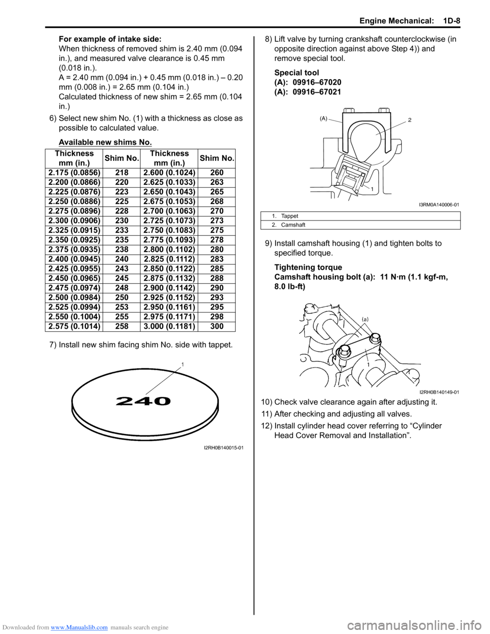
For example of intake side:
When thickness of removed shim is 2.40 mm (0.094
in.), and measured valve clearance is 0.45 mm
(0.018 in.).
A = 2.40 mm (0.094 in.) + 0.45 mm (0.018 in.) – 0.20
mm (0.008 in.) = 2.65 mm (0.104 in.)
Calculated thickness of new shim = 2.65 mm (0.104
in.)
6) Select new shim No. (1) with a thickness as close as possible to calculated value.
Available new shims No.
7) Install new shim facing shim No. side with tappet. 8) Lift valve by turning crankshaft counterclockwise (in
opposite direction against above Step 4)) and
remove special tool.
Special tool
(A): 09916–67020
(A): 09916–67021
9) Install camshaft housing (1) and tighten bolts to specified torque.
Tightening torque
Camshaft housing bolt (a ): 11 N·m (1.1 kgf-m,
8.0 lb-ft)
10) Check valve clearance again after adjusting it. 11) After checking and adjusting all valves.
12) Install cylinder head cover referring to “Cylinder Head Cover Removal and Installation”.
Thickness
mm (in.) Shim No.Thickness
mm (in.) Shim No.
2.175 (0.0856) 218 2.600 (0.1024) 260
2.200 (0.0866) 220 2.625 (0.1033) 263
2.225 (0.0876) 223 2.650 (0.1043) 265
2.250 (0.0886) 225 2.675 (0.1053) 268
2.275 (0.0896) 228 2.700 (0.1063) 270
2.300 (0.0906) 230 2.725 (0.1073) 273
2.325 (0.0915) 233 2.750 (0.1083) 275
2.350 (0.0925) 235 2.775 (0.1093) 278
2.375 (0.0935) 238 2.800 (0.1102) 280
2.400 (0.0945) 240 2.825 (0.1112) 283
2.425 (0.0955) 243 2.850 (0.1122) 285
2.450 (0.0965) 245 2.875 (0.1132) 288
2.475 (0.0974) 248 2.900 (0.1142) 290
2.500 (0.0984) 250 2.925 (0.1152) 293
2.525 (0.0994) 253 2.950 (0.1161) 295
2.550 (0.1004) 255 2.975 (0.1171) 298
2.575 (0.1014) 258 3.000 (0.1181) 300
I2RH0B140015-01
1. Tappet
2. Camshaft
(A)2
1
I3RM0A140006-01
I2RH0B140149-01
Page 316 of 1496
Downloaded from www.Manualslib.com manuals search engine 1D-31 Engine Mechanical:
7) Install camshaft housing.
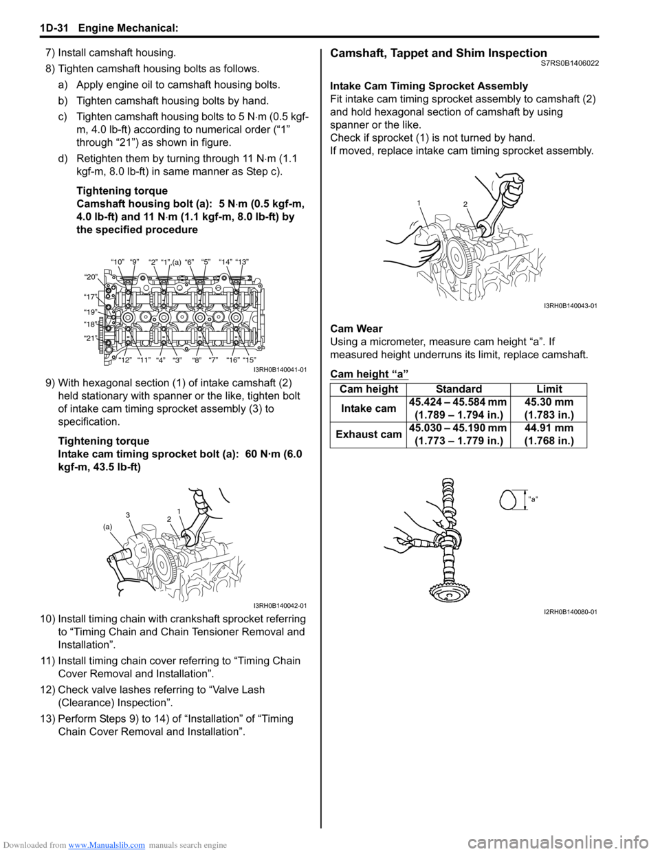
8) Tighten camshaft housing bolts as follows.a) Apply engine oil to camshaft housing bolts.
b) Tighten camshaft housing bolts by hand.
c) Tighten camshaft housing bolts to 5 N ⋅m (0.5 kgf-
m, 4.0 lb-ft) according to numerical order (“1”
through “21”) as shown in figure.
d) Retighten them by turning through 11 N⋅ m (1.1
kgf-m, 8.0 lb-ft) in same manner as Step c).
Tightening torque
Camshaft housing bolt (a): 5 N ⋅m (0.5 kgf-m,
4.0 lb-ft) and 11 N ⋅m (1.1 kgf-m, 8.0 lb-ft) by
the specified procedure
9) With hexagonal section (1) of intake camshaft (2) held stationary with spanner or the like, tighten bolt
of intake cam timing sp rocket assembly (3) to
specification.
Tightening torque
Intake cam timing sprocket bolt (a): 60 N·m (6.0
kgf-m, 43.5 lb-ft)
10) Install timing chain with cr ankshaft sprocket referring
to “Timing Chain and Chain Tensioner Removal and
Installation”.
11) Install timing chain cover referring to “Timing Chain Cover Removal and Installation”.
12) Check valve lashes referring to “Valve Lash (Clearance) Inspection”.
13) Perform Steps 9) to 14) of “Installation” of “Timing Chain Cover Removal and Installation”.Camshaft, Tappet and Shim InspectionS7RS0B1406022
Intake Cam Timing Sprocket Assembly
Fit intake cam timing sprocket assembly to camshaft (2)
and hold hexagonal section of camshaft by using
spanner or the like.
Check if sprocket (1) is not turned by hand.
If moved, replace intake ca m timing sprocket assembly.
Cam Wear
Using a micrometer, measure cam height “a”. If
measured height underruns its limit, replace camshaft.
Cam height “a”
“10”“9” “2” “1”,(a) “6” “5” “14” “13”
“20”
“17” “19”
“18”
“21”
“12”“11”
“4” “3” “8” “7” “16” “15”
I3RH0B140041-01
1
2
3
(a)
I3RH0B140042-01
Cam height Standard Limit
Intake cam 45.424 – 45.584 mm
(1.789 – 1.794 in.) 45.30 mm
(1.783 in.)
Exhaust cam 45.030 – 45.190 mm
(1.773 – 1.779 in.) 44.91 mm
(1.768 in.)
2
1
I3RH0B140043-01
I2RH0B140080-01
Page 325 of 1496
Downloaded from www.Manualslib.com manuals search engine Engine Mechanical: 1D-40
Valves and Valve Guides InspectionS7RS0B1406026
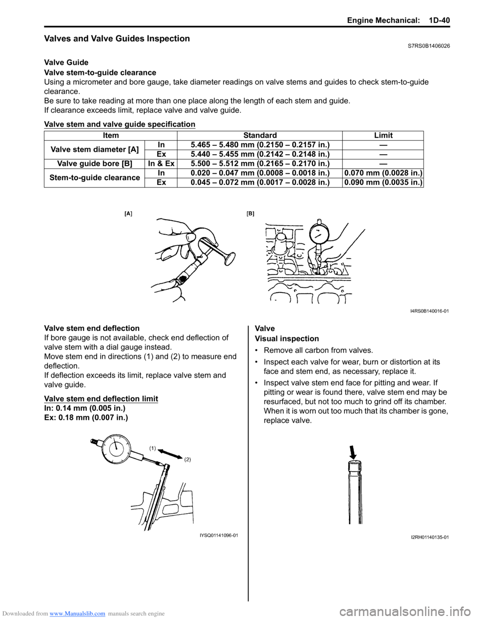
Valve Guide
Valve stem-to-guide clearance
Using a micrometer and bore gauge, take diameter readings on valve stems and guides to check stem-to-guide
clearance.
Be sure to take reading at more than one place along the length of each stem and guide.
If clearance exceeds limit, replace valve and valve guide.
Valve stem and valve guide specification
Valve stem end deflection
If bore gauge is not available, check end deflection of
valve stem with a dial gauge instead.
Move stem end in directions (1) and (2) to measure end
deflection.
If deflection exceeds its limit, replace valve stem and
valve guide.
Valve stem end deflection limit
In: 0.14 mm (0.005 in.)
Ex: 0.18 mm (0.007 in.) Va l v e
Visual inspection
• Remove all carbon from valves.
• Inspect each valve for wear, burn or distortion at its
face and stem end, as necessary, replace it.
• Inspect valve stem end face for pitting and wear. If pitting or wear is found there, valve stem end may be
resurfaced, but not too much to grind off its chamber.
When it is worn out too much that its chamber is gone,
replace valve.
Item Standard Limit
Valve stem diameter [A] In 5.465 – 5.480 mm (0.2150 – 0.2157 in.) —
Ex 5.440 – 5.455 mm (0.2142 – 0.2148 in.) —
Valve guide bore [B] In & Ex 5.500 – 5.512 mm (0.2165 – 0.2170 in.) —
Stem-to-guide clearance In 0.020 – 0.047 mm (0.0008 – 0.
0018 in.) 0.070 mm (0.0028 in.)
Ex 0.045 – 0.072 mm (0.0017 – 0. 0028 in.) 0.090 mm (0.0035 in.)
I4RS0B140016-01
IYSQ01141096-01I2RH01140135-01
Page 328 of 1496
Downloaded from www.Manualslib.com manuals search engine 1D-43 Engine Mechanical:
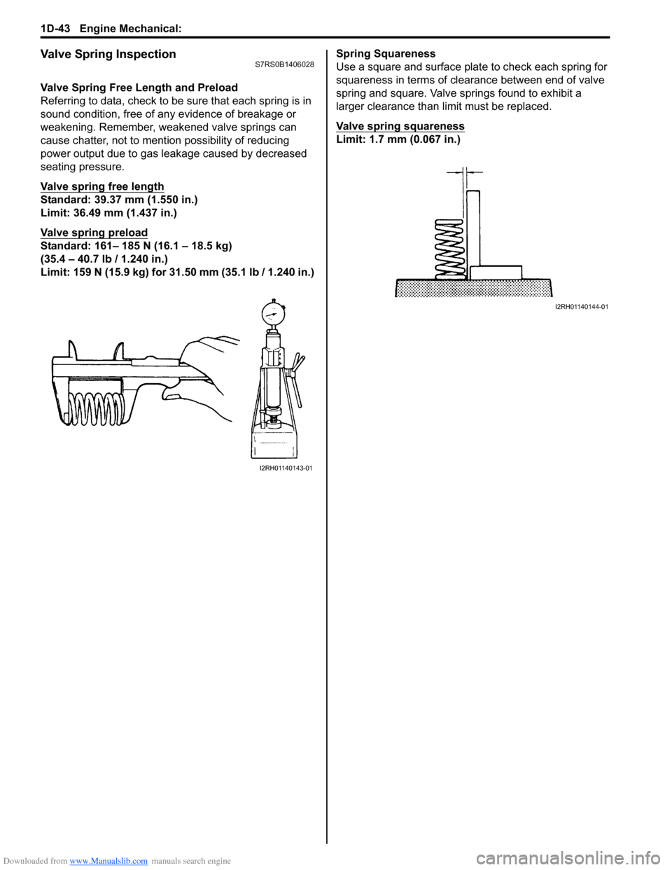
Valve Spring InspectionS7RS0B1406028
Valve Spring Free Length and Preload
Referring to data, check to be sure that each spring is in
sound condition, free of any evidence of breakage or
weakening. Remember, weakened valve springs can
cause chatter, not to mention possibility of reducing
power output due to gas leakage caused by decreased
seating pressure.
Valve spring free length
Standard: 39.37 mm (1.550 in.)
Limit: 36.49 mm (1.437 in.)
Valve spring preload
Standard: 161– 185 N (16.1 – 18.5 kg)
(35.4 – 40.7 lb / 1.240 in.)
Limit: 159 N (15.9 kg) for 31.50 mm (35.1 lb / 1.240 in.) Spring Squareness
Use a square and surface plate to check each spring for
squareness in terms of clearance between end of valve
spring and square. Valve springs found to exhibit a
larger clearance than limit must be replaced.
Valve spring squareness
Limit: 1.7 mm (0.067 in.)
I2RH01140143-01
I2RH01140144-01