2007 SUZUKI SWIFT Temp gauge
[x] Cancel search: Temp gaugePage 378 of 1496
Downloaded from www.Manualslib.com manuals search engine 1G-3 Fuel System:
4) Check that battery voltage is 11 V or more.
5) Measure fuel pressure at each condition.If measured pressure is out of specification, refer to
“Fuel Pressure Check in Section 1A” and check each
possibly defective part. Replace if found defective.
a) Turn ignition switch ON to operate fuel pump and after 2 seconds turn it OFF. Repeat this 3 or 4
times and then check fuel pressure.
Fuel pressure specification
With fuel pump operating and engine
stopped: 270 – 310 kPa (2.7 – 3.1 kg/cm2, 38.4
– 44.0 psi)
b) Start engine and warm it up to normal operating temperature, and measure fuel pressure at
idling.
Fuel pressure specification
At specified idle speed: 270 – 310 kPa (2.7 –
3.1 kg/cm2, 38.4 – 44.0 psi)
c) Stop engine, and measure fuel pressure at one minute after stopping.
Fuel pressure specification
With 1 min. after engine (fuel pump) stop
(Pressure reduces as time passes): Over 300
kPa (3.0 kg/cm
2, 42.7 psi)
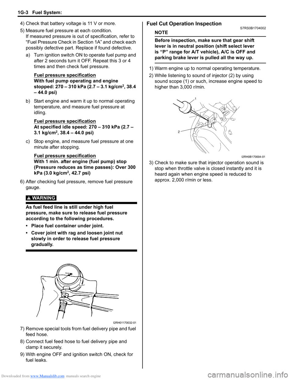
6) After checking fuel pressure, remove fuel pressure gauge.
WARNING!
As fuel feed line is still under high fuel
pressure, make sure to release fuel pressure
according to the following procedures.
• Place fuel container under joint.
• Cover joint with rag and loosen joint nut slowly in order to release fuel pressure
gradually.
7) Remove special tools from fuel delivery pipe and fuel feed hose.
8) Connect fuel feed hose to fuel delivery pipe and clamp it securely.
9) With engine OFF and ignition switch ON, check for fuel leaks.
Fuel Cut Operation InspectionS7RS0B1704002
NOTE
Before inspection, make sure that gear shift
lever is in neutral positi on (shift select lever
is “P” range for A/T vehicle), A/C is OFF and
parking brake lever is pulled all the way up.
1) Warm engine up to normal operating temperature.
2) While listening to sound of injector (2) by using sound scope (1) or such, increase engine speed to
higher than 3,000 r/min.
3) Check to make sure that injector operation sound is stop when throttle valve is closed instantly and it is
heard again when engine speed is reduced to
approx. 2,000 r/min or less.
I2RH01170032-01
I2RH0B170004-01
Page 469 of 1496

Downloaded from www.Manualslib.com manuals search engine Wheels and Tires: 2D-2
Lower than recommended pressure can cause:
• Tire squeal on turns
• Hard Steering
• Rapid and uneven wear on the edges of the tread
• Tire rim bruises and rupture
• Tire cord breakage
• High tire temperature
• Reduced handling
• High fuel consumption
Replacement Tires
When replacement is necessary, the original equipment
type tire should be used. Refer to the Tire Placard.
Replacement tires should be of the same size, load
range and construction as those originally on the vehicle.
Use of any other size or type tire may affect ride,
handling, speedometer / odometer calibration, vehicle
ground clearance and tire or snow chain clearance to the
body and chassis.
It is recommended that new tires be installed in pairs on
the same axle. If necessary to replace only one tire, it
should be paired with the tire having the most tread, to
equalize braking traction.
WARNING!
Do not mix different types of tires on the
same vehicle such as radial, bias and bias-
belted tires except in emergencies, because
handling may be seriously affected and may
result in loss of control.
The metric term for tire infl ation pressure is the kilo
pascal (kPa). Tire pressures is usually printed in both
kPa and kgf/cm
2 on the “Tire Placard”.
Metric tire gauges are available from tool suppliers.
The chart, shown the table, converts commonly used
inflation pressures from kPa to kgf/cm
2 and psi.
Wheels DescriptionS7RS0B2401002
Wheel Maintenance
Wheel repairs that use welding, heating, or peening are
not approved. All damaged wheels should be replaced.
Replacement Wheels
Wheels must be replaced if they are bent, dented, have
excessive lateral or radial runout, air leak through welds,
have elongated bolt holes, if lug wheel bolts won’t stay
tight, or if they are heavily rusted. Wheels with greater
runout than shown in the following may cause
objectional vibrations.
Replacement wheels must be equivalent to the original
equipment wheels in load capacity, diameter, rim with
offset and mounting configuration. A wheel of improper
size or type may affect wheel and bearing life, brake
cooling, speedometer / odometer calibration, vehicle
ground clearance and tire clearance to body and
chassis.
How to Measure Wheel Runout
To measure the wheel runout, it is necessary to use an
accurate dial indicator. The tire may be on or off the
wheel. The wheel should be installed to the wheel
balancer of the like for proper measurement.
Take measurements of both lateral runout “a” and radial
runout “b” at both inside an d outside of the rim flange.
With the dial indicator set in place securely, turn the
wheel one full revolution slowly and record every reading
of the indicator.
When the measured runout exceeds the specification
and correction by the balancer adjustment is impossible,
replace the wheel. If the reading is affected by welding,
paint or scratch, it should be ignored.
Lateral runout limit “a”
: 0.3 mm (0.012 in.)
Radial runout limit “b”
: 0.3 mm (0.012 in.)
kPa kgf/cm2psi
Conversion: 1 psi =
6.895 kPa 1 kgf/cm
2 =
98.066 kPa 160 1.6 23
180 1.8 26
200 2.0 29
220 2.2 32
240 2.4 35
260 2.6 38
280 2.8 41
300 3.0 44
I4RS0A240001-01
Page 676 of 1496
Downloaded from www.Manualslib.com manuals search engine 5A-32 Automatic Transmission/Transaxle:
Troubleshooting
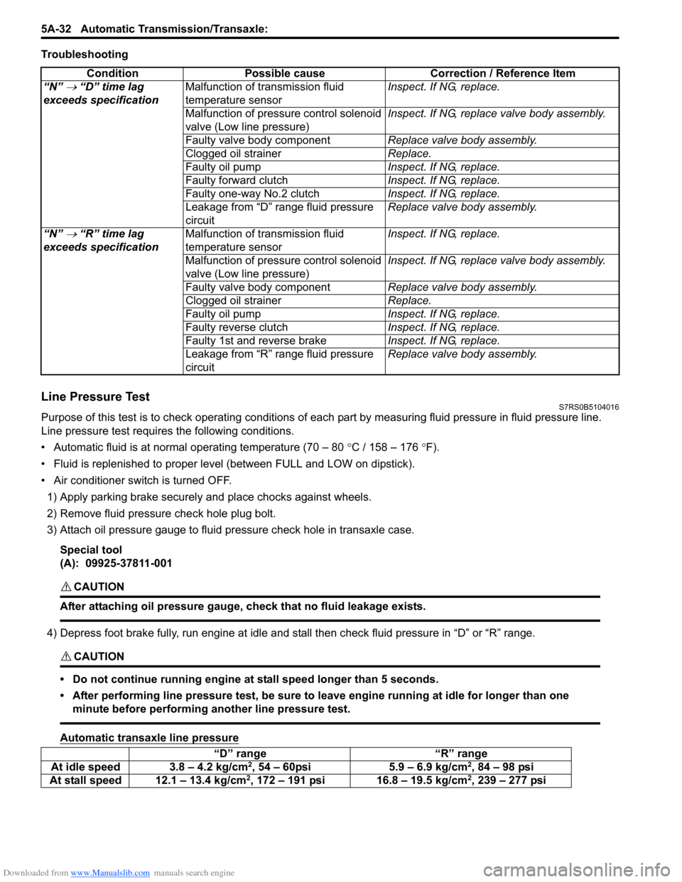
Line Pressure TestS7RS0B5104016
Purpose of this test is to check operat ing conditions of each part by measuring fluid pressure in fluid pressure line.
Line pressure test requires the following conditions.
• Automatic fluid is at normal operating temperature (70 – 80 °C / 158 – 176 °F).
• Fluid is replenished to proper level (between FULL and LOW on dipstick).
• Air conditioner switch is turned OFF.
1) Apply parking brake securely and place chocks against wheels.
2) Remove fluid pressure check hole plug bolt.
3) Attach oil pressure gauge to fluid pr essure check hole in transaxle case.
Special tool
(A): 09925-37811-001
CAUTION!
After attaching oil pressure gauge, check that no fluid leakage exists.
4) Depress foot brake fully, run engine at idle and stall then check fluid pressure in “D” or “R” range.
CAUTION!
• Do not continue running engine at stall speed longer than 5 seconds.
• After performing line pressure test, be sure to leave engine running at idle for longer than one minute before performing another line pressure test.
Automatic transaxle line pressure
Condition Possible cause Correction / Reference Item
“N”
→ “D” time lag
exceeds specification Malfunction of transmission fluid
temperature sensor Inspect. If NG, replace.
Malfunction of pressure control solenoid
valve (Low line pressure) Inspect. If NG, replace valve body assembly.
Faulty valve body component Replace valve body assembly.
Clogged oil strainer Replace.
Faulty oil pump Inspect. If NG, replace.
Faulty forward clutch Inspect. If NG, replace.
Faulty one-way No.2 clutch Inspect. If NG, replace.
Leakage from “D” range fluid pressure
circuit Replace valve body assembly.
“N”
→ “R” time lag
exceeds specification Malfunction of transmission fluid
temperature sensor Inspect. If NG, replace.
Malfunction of pressure control solenoid
valve (Low line pressure) Inspect. If NG, replace valve body assembly.
Faulty valve body component Replace valve body assembly.
Clogged oil strainer Replace.
Faulty oil pump Inspect. If NG, replace.
Faulty reverse clutch Inspect. If NG, replace.
Faulty 1st and reverse brake Inspect. If NG, replace.
Leakage from “R” range fluid pressure
circuit Replace valve body assembly.
“D” range
“R” range
At idle speed 3.8 – 4.2 kg/cm2, 54 – 60psi 5.9 – 6.9 kg/cm2, 84 – 98 psi
At stall speed 12.1 – 13.4 kg/cm2, 172 – 191 psi 16.8 – 19.5 kg/cm2, 239 – 277 psi
Page 733 of 1496
Downloaded from www.Manualslib.com manuals search engine Automatic Transmission/Transaxle: 5A-89
A/T Fluid Level CheckS7RS0B5106002
CAUTION!
Do not use any fluid other than the specified
ATF. Use of any fluid other than the specified
ATF may cause juddering or some other
faulty condition to occur.
Level Check at Normal Operating (Hot) Temperature
– Hot Check1) Drive vehicle so that A/T fluid temperature reach the
normal operating temperature (70 – 80 °C (158 –
176 °F)).
2) Stop vehicle with engine running and place it level.
3) With select lever at “P” range, apply parking brake and place chocks against wheels.
4) Keep engine idling and shift selector slowly to “L” and back to “P” position.
5) With engine idling, pull out fluid level gauge, wipe it off with a clean cloth and put it back into place.
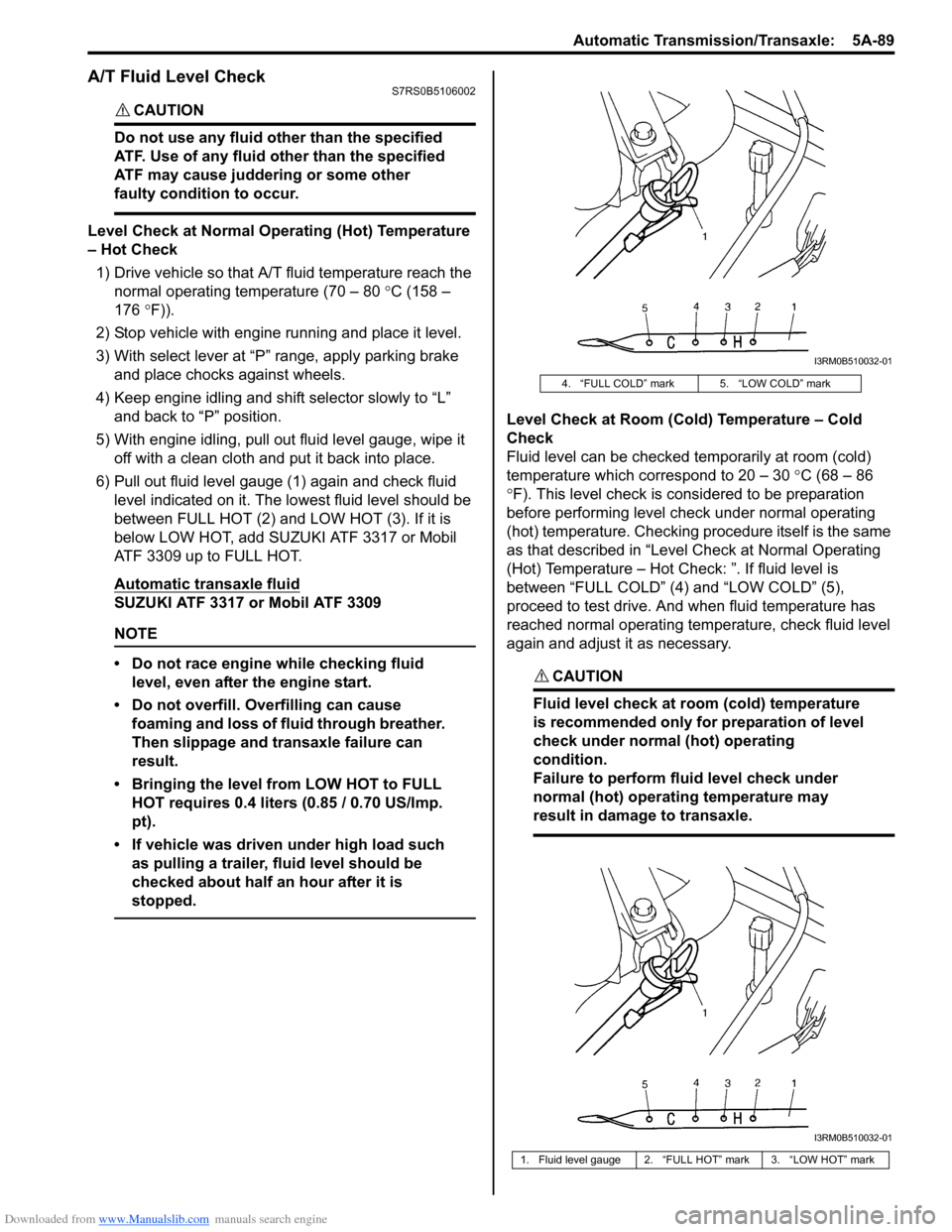
6) Pull out fluid level gauge (1) again and check fluid level indicated on it. The lo west fluid level should be
between FULL HOT (2) and LOW HOT (3). If it is
below LOW HOT, add SUZUKI ATF 3317 or Mobil
ATF 3309 up to FULL HOT.
Automatic transaxle fluid
SUZUKI ATF 3317 or Mobil ATF 3309
NOTE
• Do not race engine while checking fluid level, even after the engine start.
• Do not overfill. Overfilling can cause foaming and loss of fluid through breather.
Then slippage and transaxle failure can
result.
• Bringing the level from LOW HOT to FULL HOT requires 0.4 liters (0.85 / 0.70 US/Imp.
pt).
• If vehicle was driven under high load such as pulling a trailer, fluid level should be
checked about half an hour after it is
stopped.
Level Check at Room (Cold) Temperature – Cold
Check
Fluid level can be checked temporarily at room (cold)
temperature which correspond to 20 – 30 °C (68 – 86
° F). This level check is considered to be preparation
before performing level check under normal operating
(hot) temperature. Checking procedure itself is the same
as that described in “Level Check at Normal Operating
(Hot) Temperature – Hot Check: ”. If fluid level is
between “FULL COLD” (4) and “LOW COLD” (5),
proceed to test drive. And when fluid temperature has
reached normal operating temp erature, check fluid level
again and adjust it as necessary.
CAUTION!
Fluid level check at room (cold) temperature
is recommended only for preparation of level
check under normal (hot) operating
condition.
Failure to perform fluid level check under
normal (hot) operating temperature may
result in damage to transaxle.
4. “FULL COLD” mark 5. “LOW COLD” mark
1. Fluid level gauge 2. “FULL HOT” mark 3. “LOW HOT” mark
I3RM0B510032-01
I3RM0B510032-01
Page 755 of 1496
Downloaded from www.Manualslib.com manuals search engine Automatic Transmission/Transaxle: 5A-111
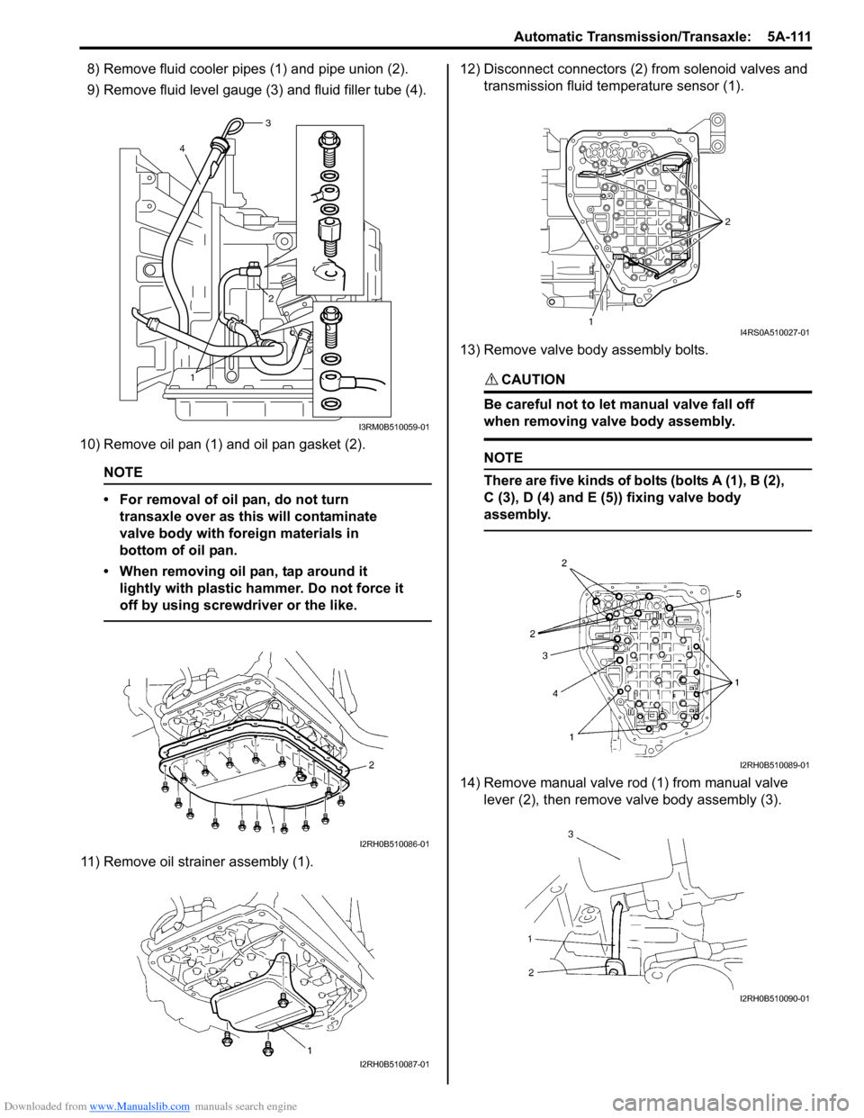
8) Remove fluid cooler pipes (1) and pipe union (2).
9) Remove fluid level gauge (3) and fluid filler tube (4).
10) Remove oil pan (1) and oil pan gasket (2).
NOTE
• For removal of oil pan, do not turn transaxle over as this will contaminate
valve body with foreign materials in
bottom of oil pan.
• When removing oil pan, tap around it lightly with plastic ha mmer. Do not force it
off by using screwdriver or the like.
11) Remove oil strain er assembly (1). 12) Disconnect connectors (2) from solenoid valves and
transmission fluid temperature sensor (1).
13) Remove valve body assembly bolts.
CAUTION!
Be careful not to let manual valve fall off
when removing valve body assembly.
NOTE
There are five kinds of bolts (bolts A (1), B (2),
C (3), D (4) and E (5)) fixing valve body
assembly.
14) Remove manual valve rod (1) from manual valve lever (2), then remove valve body assembly (3).
1 2
4
3
I3RM0B510059-01
I2RH0B510086-01
I2RH0B510087-01
1 2I4RS0A510027-01
I2RH0B510089-01
I2RH0B510090-01
Page 958 of 1496

Downloaded from www.Manualslib.com manuals search engine 7B-10 Air Conditioning System: Manual Type
Abnormal Noise from Tension Pulley
Abnormal Noise from A/C Evaporator
Abnormal Noise from Blower Motor
A/C System Performance InspectionS7RS0B7214003
1) Confirm that vehicle and environmental conditions are as follows.
• Vehicle is put indoors.
• Ambient temperature is within 25 – 35 °C (77 – 95
° F).
• Relative humidity is within 30 – 70%.
• There is no wind indoors.
• HVAC unit is normal.
• Blower motor is normal.
• There is no air leakage from air ducts.
• Condenser fins are clean.
• Air filter in HVAC unit is not clogged with dirt and
dust.
• Battery voltage is about 12 V.
• Radiator cooling fan operates normally.
2) Make sure that high pressure valve (1) and low pressure valve (2) of manifold gauge are firmly
closed.
3) Connect high pressure charging hose (3) to high pressure service valve (5) on vehicle and low
pressure charging hose (4) to low pressure service
valve (6).
4) Bleed the air in charging hoses (3) and (4) by loosening their nuts respectively utilizing the
refrigerant pressure. When a hissing sound is heard,
immediately tighten nut.
CAUTION!
Do not connect high and low pressure
charging hoses in reverse.
Condition Possible cause Correction / Reference Item
Clattering noise is heard
from pulley Worn or damaged bearing
Replace tension pulley.
Pulley cranks upon
contact Cracked or loose bracket
Replace or retighten bracket.
ConditionPossible cause Correction / Reference Item
Whistling sound is heard
from A/C evaporator Depending on the combination of the
interior / exterior temperatures, engine
rpm and refrigerant pressure, the
refrigerant flowing out of the expansion
valve may, under certain conditions,
make a whistling sound At times, slightly decrea
sing refrigerant volume
may stop this noise.
Inspect expansion valve and replace if faulty.
Condition Possible cause Correction / Reference Item
Blower motor emits a
chirping sound in
proportion to its speed of
rotation Worn or damaged motor brushes or
commutator
Replace blower motor.
Fluttering noise or large
droning noise is heard
from blower motor Leaves or other debris introduced from
fresh air inlet to blower motor
Remove debris and make sure that the screen
at fresh air inlet is intact.
53
2
1
4 6
I4RS0A720006-01
Page 959 of 1496
Downloaded from www.Manualslib.com manuals search engine Air Conditioning System: Manual Type 7B-11
5) Warm up engine to the normal operating temperature and keep it at the specified idle speed.
6) Turn A/C switch ON, set blower speed selector at maximum speed position, temperature selector at
maximum cold position, airflow selector at face
position, and air intake switch at recirculation
position. (Confirm that A/C compressor and
condenser fans are working.)
7) Wait for ten minutes to stabilize the A/C operation.
8) Open front windows, front doors and engine hood.
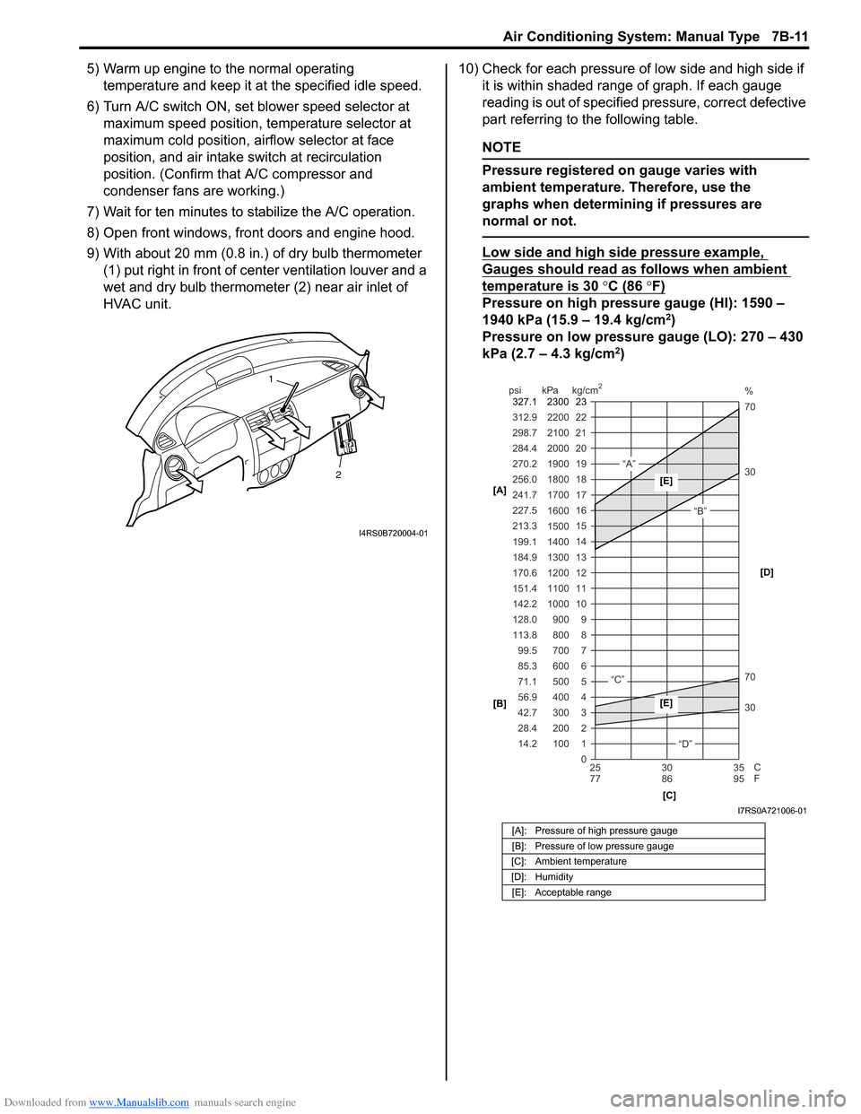
9) With about 20 mm (0.8 in.) of dry bulb thermometer
(1) put right in front of center ventilation louver and a
wet and dry bulb thermometer (2) near air inlet of
HVAC unit. 10) Check for each pressure of low side and high side if
it is within shaded range of graph. If each gauge
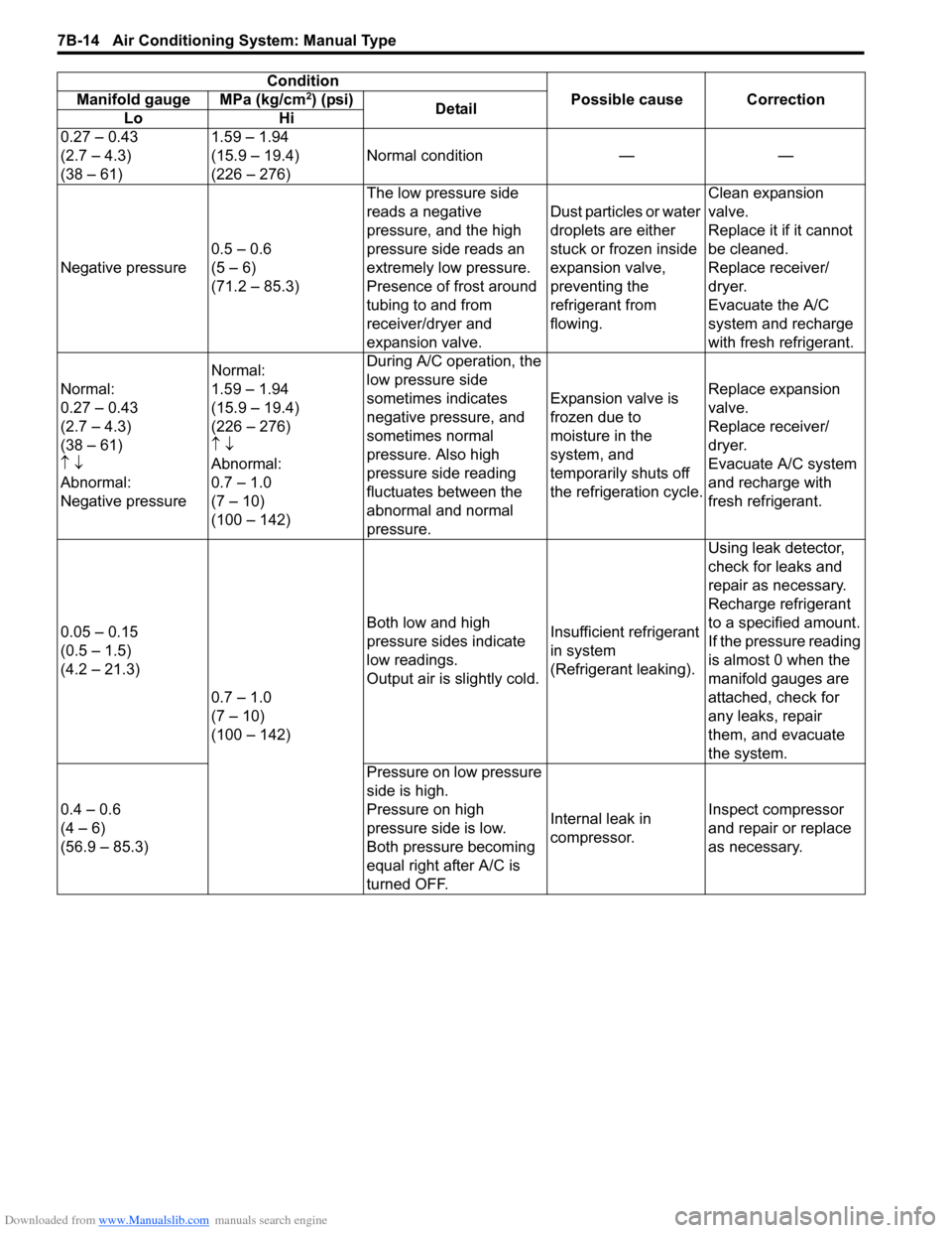
reading is out of specified pressure, correct defective
part referring to the following table.
NOTE
Pressure registered on gauge varies with
ambient temperature. Therefore, use the
graphs when determining if pressures are
normal or not.
Low side and high side pressure example,
Gauges should read as follows when ambient
temperature is 30 °C (86 °F)
Pressure on high pressure gauge (HI): 1590 –
1940 kPa (15.9 – 19.4 kg/cm2)
Pressure on low pressure gauge (LO): 270 – 430
kPa (2.7 – 4.3 kg/cm
2)
2
1
I4RS0B720004-01
[A]: Pressure of high pressure gauge
[B]: Pressure of low pressure gauge
[C]: Ambient temperature
[D]: Humidity [E]: Acceptable range
22
312.9 2200
0 1
2 3 30 70 30 70 %
4 5 6 7 8 9
10
11 12 13 14 15
16 17
18
19 21
298.7 2100
20
14.2 28.4 42.7 56.9 71.1 85.3 99.5
113.8 128.0 142.2
151.4
170.6
184.9 199.1
213.3 227.5
241.7
256.0
270.2
284.4
100 200 300 400 500 600 700 800 900
1000 1100 1200
1300
1400 1500 1600
1700 1800
1900
2000
25 30 35
77 86 95
psi kPa kg/cm
2
C
F
“A”
“B”
“C”
“D”
23
2300
327.1
[A]
[B]
[C][D][E]
[E]
I7RS0A721006-01
Page 962 of 1496
Downloaded from www.Manualslib.com manuals search engine 7B-14 Air Conditioning System: Manual Type
ConditionPossible cause Correction
Manifold gauge MPa (kg/cm2) (psi)
Detail
Lo Hi
0.27 – 0.43
(2.7 – 4.3)
(38 – 61) 1.59 – 1.94
(15.9 – 19.4)
(226 – 276)
Normal condition — —
Negative pressure 0.5 – 0.6
(5 – 6)
(71.2 – 85.3) The low pressure side
reads a negative
pressure, and the high
pressure side reads an
extremely low pressure.
Presence of frost around
tubing to and from
receiver/dryer and
expansion valve. Dust particles or water
droplets are either
stuck or frozen inside
expansion valve,
preventing the
refrigerant from
flowing.Clean expansion
valve.
Replace it if it cannot
be cleaned.
Replace receiver/
dryer.
Evacuate the A/C
system and recharge
with fresh refrigerant.
Normal:
0.27 – 0.43
(2.7 – 4.3)
(38 – 61)
↑ ↓
Abnormal:
Negative pressure Normal:
1.59 – 1.94
(15.9 – 19.4)
(226 – 276)
↑
↓
Abnormal:
0.7 – 1.0
(7 – 10)
(100 – 142) During A/C operation, the
low pressure side
sometimes indicates
negative pressure, and
sometimes normal
pressure. Also high
pressure side reading
fluctuates between the
abnormal and normal
pressure.
Expansion valve is
frozen due to
moisture in the
system, and
temporarily shuts off
the refrigeration cycle.
Replace expansion
valve.
Replace receiver/
dryer.
Evacuate A/C system
and recharge with
fresh refrigerant.
0.05 – 0.15
(0.5 – 1.5)
(4.2 – 21.3) 0.7 – 1.0
(7 – 10)
(100 – 142) Both low and high
pressure sides indicate
low readings.
Output air is slightly cold.
Insufficient refrigerant
in system
(Refrigerant leaking).Using leak detector,
check for leaks and
repair as necessary.
Recharge refrigerant
to a specified amount.
If the pressure reading
is almost 0 when the
manifold gauges are
attached, check for
any leaks, repair
them, and evacuate
the system.
0.4 – 0.6
(4 – 6)
(56.9 – 85.3) Pressure on low pressure
side is high.
Pressure on high
pressure side is low.
Both pressure becoming
equal right after A/C is
turned OFF.
Internal leak in
compressor.
Inspect compressor
and repair or replace
as necessary.