2007 SUZUKI SWIFT Spare
[x] Cancel search: SparePage 513 of 1496
Downloaded from www.Manualslib.com manuals search engine Brake Control System and Diagnosis: 4A-15
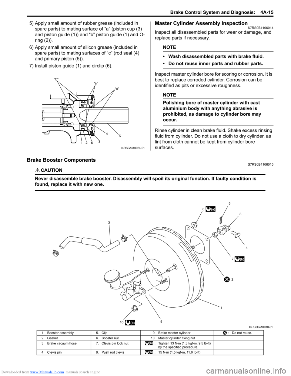
5) Apply small amount of rubber grease (included in spare parts) to mating surface of “a” (piston cup (3)
and piston guide (1)) and “b” piston guide (1) and O-
ring (2)).
6) Apply small amount of s ilicon grease (included in
spare parts) to mating surfaces of “c” (rod seal (4)
and primary piston (5)).
7) Install piston guide (1) and circlip (6).Master Cylinder Assembly InspectionS7RS0B4106014
Inspect all disassembled parts for wear or damage, and
replace parts if necessary.
NOTE
• Wash disassembled parts with brake fluid.
• Do not reuse inner parts and rubber parts.
Inspect master cylinder bore for scoring or corrosion. It is
best to replace corroded cylinder. Corrosion can be
identified as pits or excessive roughness.
NOTE
Polishing bore of master cylinder with cast
aluminium body with anything abrasive is
prohibited, as damage to cylinder bore may
occur.
Rinse cylinder in clean brake fluid. Shake excess rinsing
fluid from cylinder. Do not use a cloth to dry cylinder, as
lint from cloth cannot be kept from cylinder bore
surfaces.
Brake Booster ComponentsS7RS0B4106015
CAUTION!
Never disassemble brake booster. Disassembly will spoi l its original function. If faulty condition is
found, replace it with new one.
I4RS0A410024-01
9
10 17
4
8
5
6
3
(b)
(a)
(b)
2
I6RS0C410010-01
1. Booster assembly 5. Clip 9. Brake master cylinder : Do not reuse.
2. Gasket 6. Booster nut 10. Master cylinder fixing nut
3. Brake vacuum hose 7. Clevis pin lock nut : Tighten 13 N⋅m (1.3 kgf-m, 9.5 lb-ft)
by the specified procedure.
4. Clevis pin 8. Push rod clevis : 15 N⋅m (1.5 kgf-m, 11.0 lb-ft)
Page 518 of 1496
Downloaded from www.Manualslib.com manuals search engine 4B-2 Front Brakes:
Front Disc Brake Pad On-Vehicle InspectionS7RS0B4206002
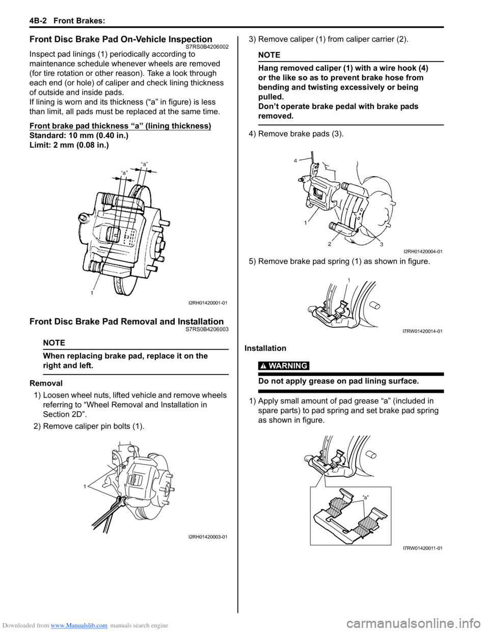
Inspect pad linings (1) periodically according to
maintenance schedule whenever wheels are removed
(for tire rotation or other reason). Take a look through
each end (or hole) of caliper and check lining thickness
of outside and inside pads.
If lining is worn and its thic kness (“a” in figure) is less
than limit, all pads must be replaced at the same time.
Front brake pad thickness “a” (lining thickness)
Standard: 10 mm (0.40 in.)
Limit: 2 mm (0.08 in.)
Front Disc Brake Pad Removal and InstallationS7RS0B4206003
NOTE
When replacing brake pad, replace it on the
right and left.
Removal
1) Loosen wheel nuts, lifted vehicle and remove wheels referring to “Wheel Remova l and Installation in
Section 2D”.
2) Remove caliper pin bolts (1). 3) Remove caliper (1) from caliper carrier (2).
NOTE
Hang removed caliper (1) with a wire hook (4)
or the like so as to prevent brake hose from
bending and twisting excessively or being
pulled.
Don’t operate brake pedal with brake pads
removed.
4) Remove brake pads (3).
5) Remove brake pad spring (1) as shown in figure.
Installation
WARNING!
Do not apply grease on pad lining surface.
1) Apply small amount of pad grease “a” (included in spare parts) to pad spring and set brake pad spring
as shown in figure.
I2RH01420001-01
1
I2RH01420003-01
I2RH01420004-01
1
I7RW01420014-01
"a"
I7RW01420011-01
Page 526 of 1496
Downloaded from www.Manualslib.com manuals search engine 4C-2 Rear Brakes:
Rear Disc Brake Pad Removal and InstallationS7RS0B4306002
NOTE
When replacing brake pad, replace it on the
right and left.
Removal1) Hoist vehicle and remove wheel.
2) Release parking brake lever.
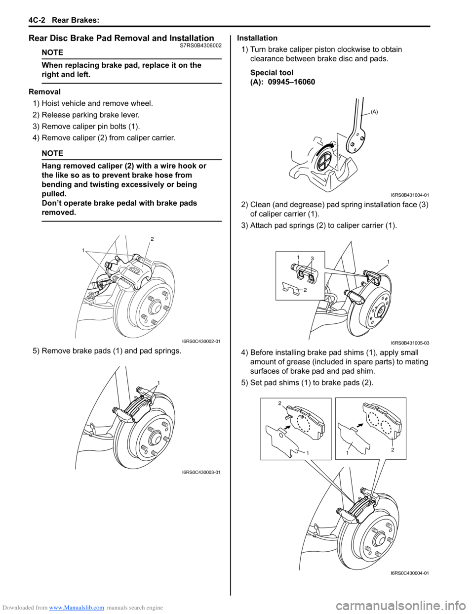
3) Remove caliper pin bolts (1).
4) Remove caliper (2) from caliper carrier.
NOTE
Hang removed caliper (2) with a wire hook or
the like so as to prevent brake hose from
bending and twisting excessively or being
pulled.
Don’t operate brake pedal with brake pads
removed.
5) Remove brake pads (1) and pad springs. Installation
1) Turn brake caliper piston clockwise to obtain clearance between brake disc and pads.
Special tool
(A): 09945–16060
2) Clean (and degrease) pad spring installation face (3) of caliper carrier (1).
3) Attach pad springs (2) to caliper carrier (1).
4) Before installing brake p ad shims (1), apply small
amount of grease (included in spare parts) to mating
surfaces of brake pad and pad shim.
5) Set pad shims (1) to brake pads (2).
1 2
I6RS0C430002-01
1
I6RS0C430003-01
(A)
I6RS0B431004-01
113
2
I6RS0B431005-03
2
1
1 2
I6RS0C430004-01
Page 1032 of 1496
Downloaded from www.Manualslib.com manuals search engine 8A-1 Seat Belts:
Restraint
Seat Belts
Precautions
Precautions on Service and Diagnosis of Seat
Belt
S7RS0B8100001
WARNING!
If replacing seat belt is necessary, replace
buckle and seat belt assembly together as a
set. This is for the reason of ensuring locking
of tongue plate with buckle. If these parts are
replaced individually, such a locking
condition may become unreliable. For this
reason, SUZUKI will supply only the spare
buckle and seat belt assembly in a set part.
Before servicing or replacing seat belts, refer to the
following precautionary items.
• Seat belts should be normal relative to strap retractor and buckle portions. • Keep sharp edges and damaging objects away from
belts.
• Avoid bending or damaging any portion of belt buckle or latch plate.
• Do not bleach or dye belt webbing. (Use only mild soap and lukewarm water to clean it.)
• When installing a seat belt anchor bolt, it should be tightened by hand at first to prevent cross-threading
and then to specified torque.
• Do not attempt any repair s on retractor mechanisms
or retractor covers. Replace defective assemblies with
new replacement parts.
• Keep belts dry and clean at all times.
• If there exist any parts in question, replace such parts.
• Replace belts whose webbing is cut or otherwise damaged.
• Do not put anything into trim panel opening which seat belt webbing passes through.
General Description
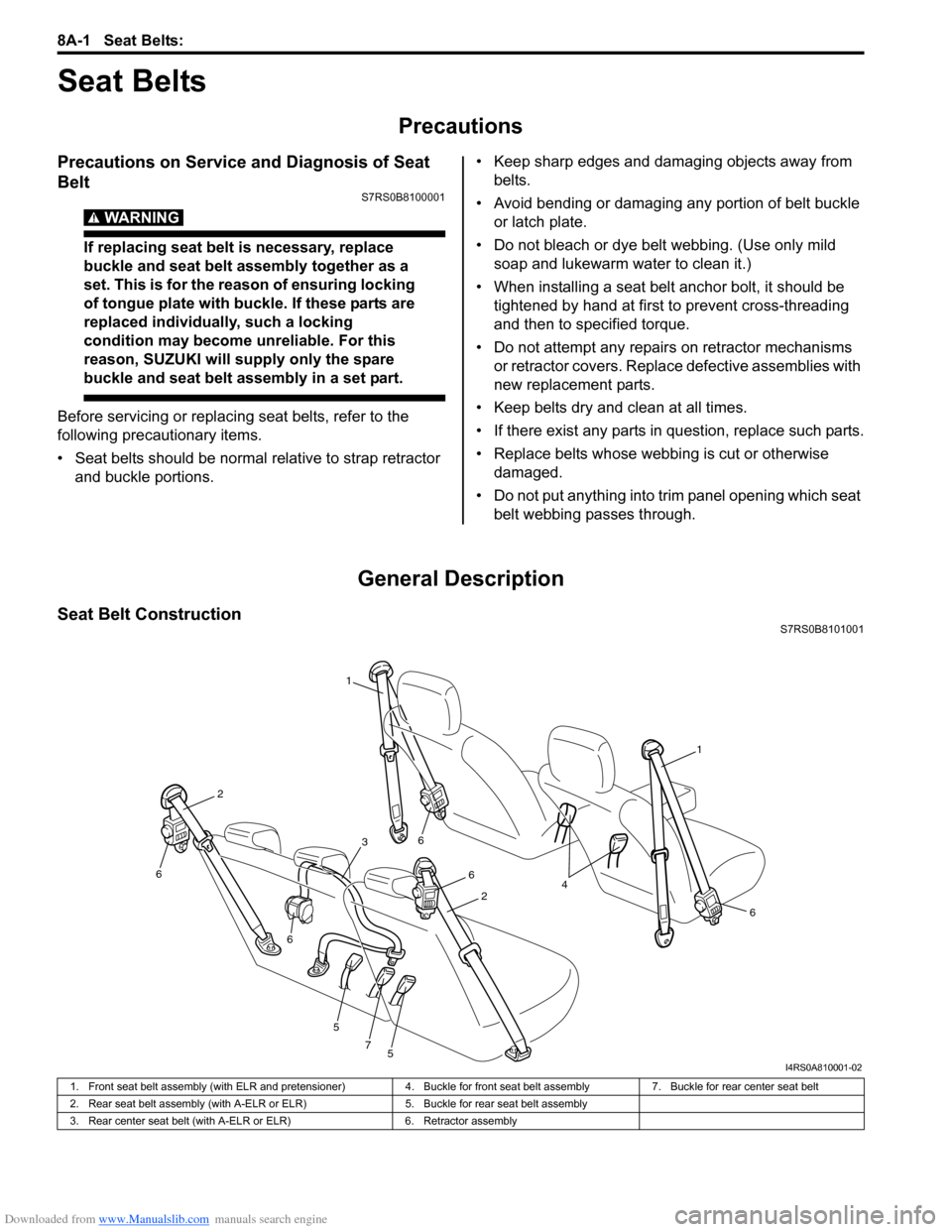
Seat Belt ConstructionS7RS0B8101001
1
1
6
6
6
5
5
7
6
6
2
2
3
4
I4RS0A810001-02
1. Front seat belt assembly (with ELR and pretensioner) 4. Buckle for front seat belt assembly7. Buckle for rear center seat belt
2. Rear seat belt assembly (with A-ELR or ELR) 5. Buckle for rear seat belt assembly
3. Rear center seat belt (with A-ELR or ELR) 6. Retractor assembly
Page 1158 of 1496
Downloaded from www.Manualslib.com manuals search engine 8B-120 Air Bag System:
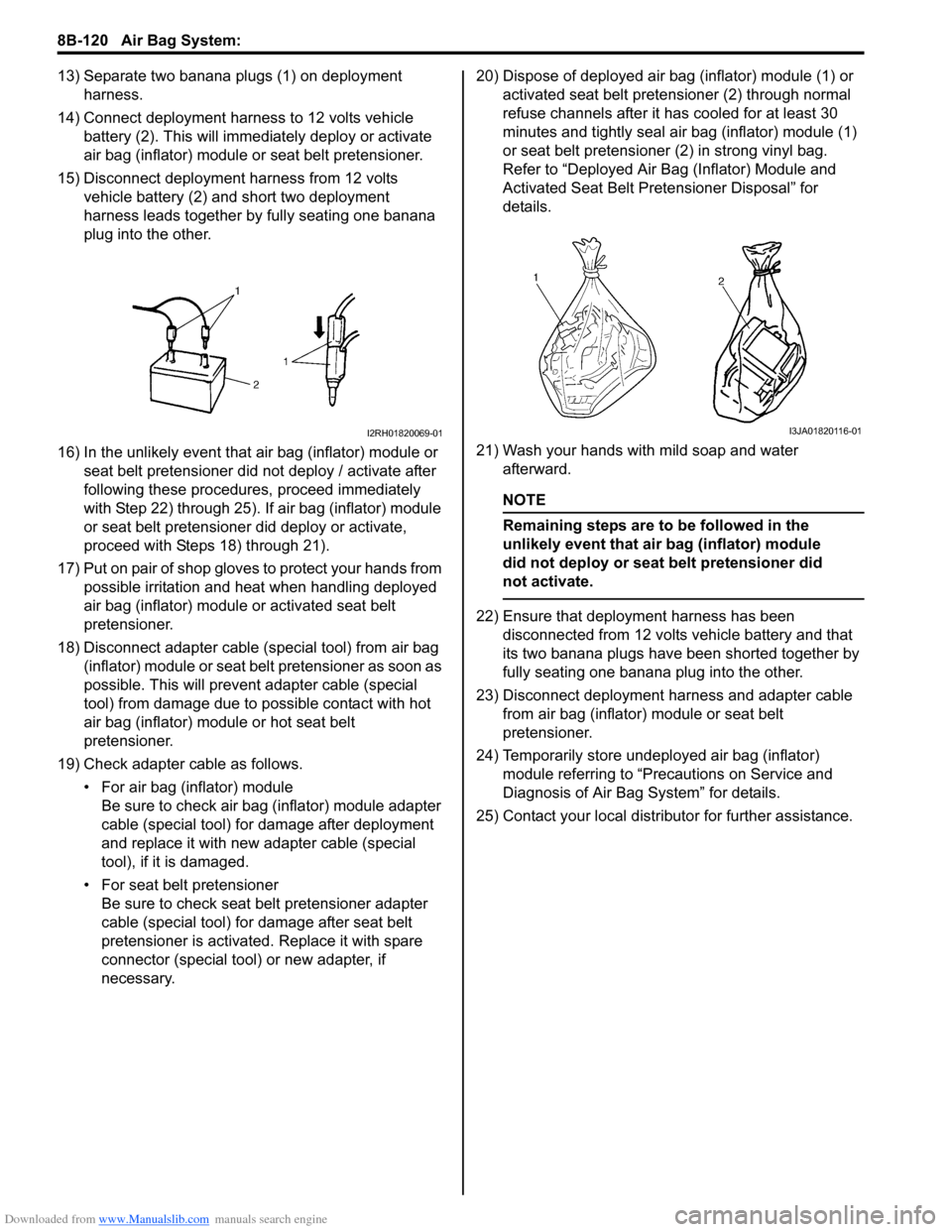
13) Separate two banana plugs (1) on deployment harness.
14) Connect deployment harness to 12 volts vehicle battery (2). This will immedi ately deploy or activate
air bag (inflator) module or seat belt pretensioner.
15) Disconnect deployment harness from 12 volts vehicle battery (2) and short two deployment
harness leads together by fully seating one banana
plug into the other.
16) In the unlikely event that air bag (inflator) module or seat belt pretensioner did not deploy / activate after
following these procedur es, proceed immediately
with Step 22) through 25). If air bag (inflator) module
or seat belt pretensioner did deploy or activate,
proceed with Steps 18) through 21).
17) Put on pair of shop gloves to protect your hands from possible irritation and heat when handling deployed
air bag (inflator) module or activated seat belt
pretensioner.
18) Disconnect adapter cable (special tool) from air bag (inflator) module or seat belt pretensioner as soon as
possible. This will preven t adapter cable (special
tool) from damage due to possible contact with hot
air bag (inflator) module or hot seat belt
pretensioner.
19) Check adapter cable as follows. • For air bag (inflator) moduleBe sure to check air bag (inflator) module adapter
cable (special tool) for damage after deployment
and replace it with new adapter cable (special
tool), if it is damaged.
• For seat belt pretensioner Be sure to check seat belt pretensioner adapter
cable (special tool) for damage after seat belt
pretensioner is activated. Replace it with spare
connector (special tool) or new adapter, if
necessary. 20) Dispose of deployed air bag (inflator) module (1) or
activated seat belt preten sioner (2) through normal
refuse channels after it has cooled for at least 30
minutes and tightly seal air bag (inflator) module (1)
or seat belt pretensioner (2) in strong vinyl bag.
Refer to “Deployed Air B ag (Inflator) Module and
Activated Seat Belt Pretensioner Disposal” for
details.
21) Wash your hands with mild soap and water afterward.
NOTE
Remaining steps are to be followed in the
unlikely event that air bag (inflator) module
did not deploy or seat belt pretensioner did
not activate.
22) Ensure that deployment harness has been disconnected from 12 volts vehicle battery and that
its two banana plugs have been shorted together by
fully seating one banana plug into the other.
23) Disconnect deployment harness and adapter cable from air bag (inflator) module or seat belt
pretensioner.
24) Temporarily store undeployed air bag (inflator) module referring to “Precautions on Service and
Diagnosis of Air Bag System” for details.
25) Contact your local distributor for further assistance.
I2RH01820069-01I3JA01820116-01
Page 1210 of 1496
Downloaded from www.Manualslib.com manuals search engine 9A-39 Wiring Systems:
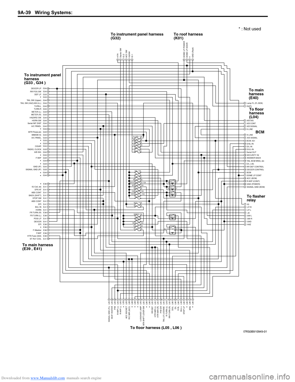
1IG2FL2
6
Lamp FL (FL BOX)
1A/B CONT4A/B SIG
3K-LINE2A/B SIGNAL
9A/B SIGNAL8K-LINE
2311BCM ;IG1
22D/UL-IN21D/L-IN D/SL-IN
18SECURITY IN6Serial OUT
14TAIL BCM WNG, etc12ANSWER BACK
17RR DEF CONTROL1D/L (+B)
2BCM15DEICER CONTROL
10ACC (BCM)7DOME LP CONT
20GND (POWER)16R-WIP (CONT)
3SIGNAL GND (BCM)
7IG
1LP-L5LP-R
8+B6SW-L
3GND4SW-R
2HAZ
DOME LP POWER5DOME LP DOOR4*3GND (Roof)6HTR4Starter SW1IG 25ACC SW3IG2SW2IG 1
18107G33415G347G3419G341G3412G339G3311G343G342G348G34166G336G345G33810511G3313G344G341G3320G342G339G343G3312G3414G34
10E395E4112E419E4114E411E418E412E4111E413E416E395E3916E417E414E392E399E393E397E3910E41
DEF LP
RR FOG SW DEICER LP
*TAIL SW (Upper)
TAIL SW (HAZ,ASH,ILL) TURN-L
TURN-R
METER (L)
METER (R)
HAZARD SW HORN SW
Serial INF DISP
A/C PANEL
*MTR Power,etc
IMMOBI IG
A/C PANEL
*
*
RADIO, CLOCK
A/B SIGCIGAR
*F-WIP*
*GND (IP)
SIGNAL GND (IP)
*
*
*
IG Coil, etc EPS AT
ABS CONT
BACK (SHIFT) STOP SW
ABS CONT EPI
BUL IN
HORN
FR TURN (R)
FR TURN (L) POSI LP
EPI
DEICER
*F-Washer
F.WIP
HTR Fuse (30A)
ST RLY COIL
4L0515L0516L055L059L05212L0513L0614L067L0615L0614L0511L056L065L068L057L056L0518L053L051L0510L059L0610L061L063L062L068L0611L064L06
SIGNAL GND (FL)
SEAT HEATER
P/W
R-WIP (+) R-WIP (-)*
ACC SOCKET
R/C MIR (ACC)
*
*
*
LUGGAGE LAMPMTA SHIFT LEVER SW
*
*
RR DEF
HTR MIR (L)
HTR MIR (R)
P/W DR
TAIL LP, LICENSE
R-TURN (L)
RR-TURN (R)
D/ULD/L
D-SL
BUL-L
STOP LP
MTA
*
*
IG COIL 15AMETER 10A A/BAG 15A
IG1 SIG 10A ABS 10A
BACK 10A
TAIL 10AD/L 20A
P/WT 20A
RR DEF 20A
DEICER/RR FOG 15A
MTA/HID R 10A
ACC 1 15A
ACC 2 15A
WIPER 15A P/W 30A
*Spare-1
SEAT HTR 15A IG2 SIG 10AST SIG 10A
HAZ-HORN 15A
DIESEL/HID L 10A *Spare-2 RR DEF RLY
DEICER RLY HORN RLY
P-WIP RLY
BLOWER MOTOR RLY
G34 G34
G33
G34
G33
G34 G33
L05
RADIO 15A
To instrument panel harness
(G32) To roof harness
(K01)
To instrument panel
harness
(G33 , G34 )
To main harness
(E39 , E41) To floor harness (L05 , L06 ) To main
harness
(E40)
BCM
To flasher
relay To floor
harness
(L04)
* : Not used
I7RS0B910949-01
Page 1452 of 1496
Downloaded from www.Manualslib.com manuals search engine 10C-9 Immobilizer Control System:
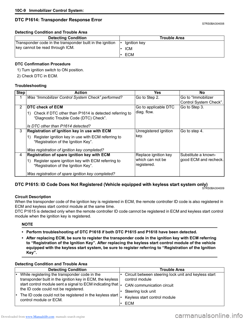
DTC P1614: Transponder Response ErrorS7RS0BA304008
Detecting Condition and Trouble Area
DTC Confirmation Procedure
1) Turn ignition switch to ON position.
2) Check DTC in ECM.
Troubleshooting
DTC P1615: ID Code Does Not Registered (Vehicle equipped with keyless start system only)S7RS0BA304009
Circuit Description
When the transponder code of the ignition key is registered in ECM, the remote controller ID code is also registered in
ECM and keyless start contro l module at the same time.
DTC P1615 is detected only when the remote controller ID code cannot be registered in ECM and keyless start control
module when the ignition key is registered.
NOTE
• Perform troubleshooting of DTC P1618 if both DTC P1615 and P1618 have been detected.
• After replacing ECM, be sure to register the tran sponder code in the ignition key with ECM referring
to “Registration of the Ignition Key”. After replac ing the keyless start control module of the vehicle
equipped with the keyless start system, be sure to register referring to “Registration of the Ignition
Key”.
Detecting Condition and Trouble Area Detecting Condition Trouble Area
Transponder code in the transponder built in the ignition
key cannot be read through ICM. • Ignition key
•ICM
•ECM
Step
Action YesNo
1 Was “Immobilizer Control S ystem Check” performed? Go to Step 2.Go to “Immobilizer
Control System Check”.
2 DTC check of ECM
1) Check if DTC other than P1614 is detected referring to
“Diagnostic Trouble Code (DTC) Check”.
Is DTC other than P1614 detected? Go to applicable DTC
diag. flow.
Go to Step 3.
3 Registration of ignition key in use with ECM
1) Register ignition key in use with ECM referring to
“Registration of the Ignition Key”.
Was registration of ignition key completed? Unregistered ignition
key.
Go to step 4.
4 Registration of spare ignition key with ECM
1) Register spare ignition key with ECM referring to
“Registration of the Ignition Key”.
Was registration of spare ignition key completed? Replace ignition key
which can not be
registered.
Substitute a known-
good ECM and recheck.
Detecting Condition
Trouble Area
• While registering the transponder code in the transponder built in the ignition key in ECM, the keyless
start control module sent a signal to ECM indicating that
the ID code could not be registered.
• The ID code could not be registered in the keyless start control module or ECM. • Circuit between steering lo
ck unit and keyless start
control module
• CAN communication circuit
• Steering lock unit
• Keyless start control module
•ECM
Page 1457 of 1496
Downloaded from www.Manualslib.com manuals search engine Immobilizer Control System: 10C-14
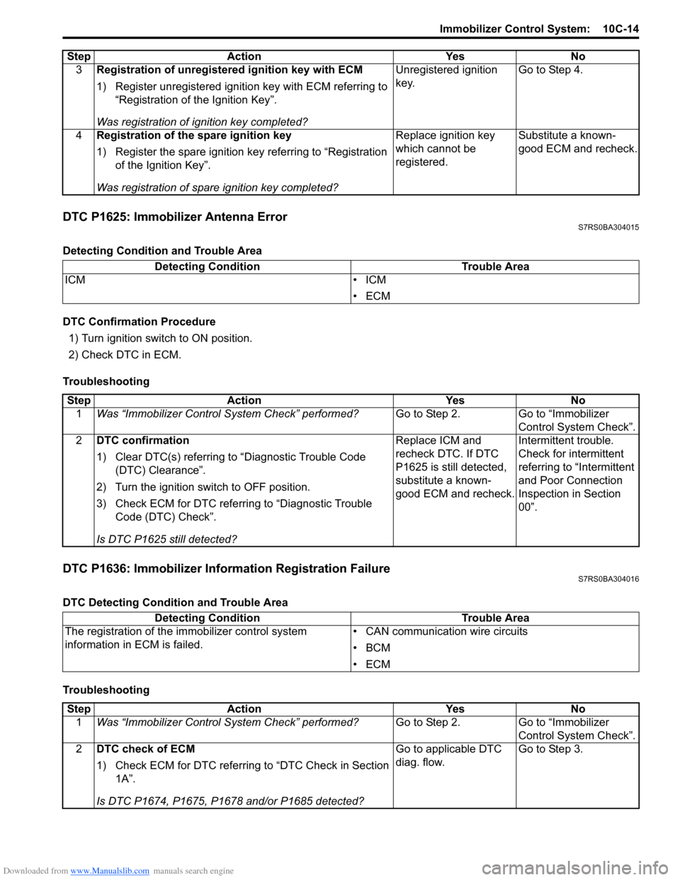
DTC P1625: Immobilizer Antenna ErrorS7RS0BA304015
Detecting Condition and Trouble Area
DTC Confirmation Procedure1) Turn ignition switch to ON position.
2) Check DTC in ECM.
Troubleshooting
DTC P1636: Immobilizer Information Registration FailureS7RS0BA304016
DTC Detecting Condition and Trouble Area
Troubleshooting 3
Registration of unregistered ignition key with ECM
1) Register unregistered igniti on key with ECM referring to
“Registration of the Ignition Key”.
Was registration of ignition key completed? Unregistered ignition
key.
Go to Step 4.
4 Registration of the spare ignition key
1) Register the spare ignition key referring to “Registration
of the Ignition Key”.
Was registration of spare ignition key completed? Replace ignition key
which cannot be
registered.
Substitute a known-
good ECM and recheck.
Step Action Yes No
Detecting Condition
Trouble Area
ICM • ICM
•ECM
StepAction YesNo
1 Was “Immobilizer Control S ystem Check” performed? Go to Step 2.Go to “Immobilizer
Control System Check”.
2 DTC confirmation
1) Clear DTC(s) referring to “Diagnostic Trouble Code
(DTC) Clearance”.
2) Turn the ignition switch to OFF position.
3) Check ECM for DTC referring to “Diagnostic Trouble Code (DTC) Check”.
Is DTC P1625 still detected? Replace ICM and
recheck DTC. If DTC
P1625 is still detected,
substitute a known-
good ECM and recheck.
Intermittent trouble.
Check for intermittent
referring to “Intermittent
and Poor Connection
Inspection in Section
00”.
Detecting Condition
Trouble Area
The registration of the immobilizer control system
information in ECM is failed. • CAN communication wire circuits
•BCM
•ECM
Step
Action YesNo
1 Was “Immobilizer Control S ystem Check” performed? Go to Step 2.Go to “Immobilizer
Control System Check”.
2 DTC check of ECM
1) Check ECM for DTC referring to “DTC Check in Section
1A”.
Is DTC P1674, P1675, P1678 and/or P1685 detected? Go to applicable DTC
diag. flow.
Go to Step 3.