2007 SUZUKI SWIFT No Heater output
[x] Cancel search: No Heater outputPage 231 of 1496
Downloaded from www.Manualslib.com manuals search engine Engine General Information and Diagnosis: 1A-181
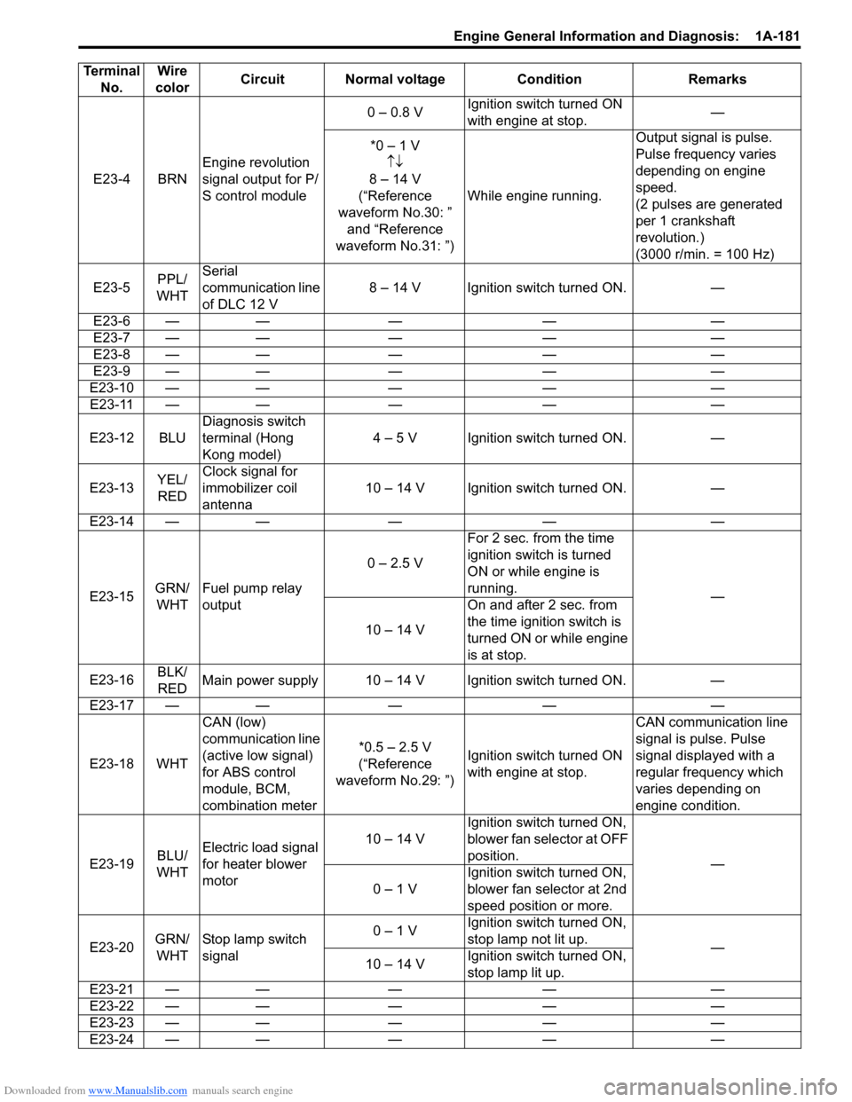
E23-4 BRNEngine revolution
signal output for P/
S control module 0 – 0.8 V
Ignition switch turned ON
with engine at stop. —
*0 – 1 V ↑↓
8 – 14 V
(“Reference
waveform No.30: ” and “Reference
waveform No.31: ”) While engine running. Output signal is pulse.
Pulse frequency varies
depending on engine
speed.
(2 pulses are generated
per 1 crankshaft
revolution.)
(3000 r/min. = 100 Hz)
E23-5 PPL/
WHT Serial
communication line
of DLC 12 V
8 – 14 V Ignition switch turned ON. —
E23-6 — — — — —
E23-7 — — — — —
E23-8 — — — — —
E23-9 — — — — —
E23-10 — — — — — E23-11 — — — — —
E23-12 BLU Diagnosis switch
terminal (Hong
Kong model) 4 – 5 V Ignition switch turned ON. —
E23-13 YEL/
RED Clock signal for
immobilizer coil
antenna
10 – 14 V Ignition switch turned ON. —
E23-14 — — — — —
E23-15 GRN/
WHT Fuel pump relay
output 0 – 2.5 V
For 2 sec. from the time
ignition switch is turned
ON or while engine is
running.
—
10 – 14 V On and after 2 sec. from
the time ignition switch is
turned ON or while engine
is at stop.
E23-16 BLK/
RED Main power supply 10 – 14 V Ignition switch turned ON. —
E23-17 — — — — —
E23-18 WHT CAN (low)
communication line
(active low signal)
for ABS control
module, BCM,
combination meter *0.5 – 2.5 V
(“Reference
waveform No.29: ”) Ignition switch turned ON
with engine at stop. CAN communication line
signal is pulse. Pulse
signal displayed with a
regular frequency which
varies depending on
engine condition.
E23-19 BLU/
WHT Electric load signal
for heater blower
motor 10 – 14 V
Ignition switch turned ON,
blower fan selector at OFF
position.
—
0 – 1 V Ignition switch turned ON,
blower fan selector at 2nd
speed position or more.
E23-20 GRN/
WHT Stop lamp switch
signal 0 – 1 V
Ignition switch turned ON,
stop lamp not lit up.
—
10 – 14 V Ignition switch turned ON,
stop lamp lit up.
E23-21 — — — — —
E23-22 — — — — —
E23-23 — — — — —
E23-24 — — — — —
Terminal
No. Wire
color Circuit Normal voltage Condition Remarks
Page 302 of 1496

Downloaded from www.Manualslib.com manuals search engine 1D-17 Engine Mechanical:
Engine Assembly Removal and InstallationS7RS0B1406011
NOTE
After replacing electric throttle body
assembly, perform calibration of throttle
valve referring to “Electric Throttle Body
System Calibration in Section 1C”.
Removal1) Relieve fuel pressure according to “Fuel Pressure Relief Procedure in Section 1G”.
2) Disconnect negative and pos itive cable at battery.
3) Remove battery and tray.
4) Remove engine hood after disconnecting windshield washer hose.
5) Remove right and left side engine under covers.
6) Remove A/C compressor belt by referring to “Compressor Drive Belt Remo val and Installation in
Section 7B” or “Compressor Drive Belt Removal and
Installation in Section 7B”.
7) Drain engine oil, transaxle oil and coolant.
8) Remove cowl top plate referring to “Cowl Top Components in Section 9K”.
9) Remove air cleaner assembly referring to “Air Cleaner Components”.
10) With hose connected, detach A/C compressor from its bracket (A/C model) referring to “Compressor
Assembly Removal and Installation in Section 7B” or
“Compressor Assembly Removal and Installation in
Section 7B”.
CAUTION!
Suspend removed A/C compressor at a place
where no damage will be caused during
removal and installation of engine assembly.
11) Remove intake manifold rear stiffener (1) from intake manifold and cylinder block. 12) Disconnect the following electric wires:
• MAP sensor (1)
• ECT sensor (2)
•EGR valve (3)
• CMP sensor (4)
• Electric throttle body assembly (5)
• Ignition coil assembly (6)
• Injectors (7)
• Heated oxygen sensor No. 2 (8) and No. 1 (9)
• Oil control valve (10)
• Engine oil pressure switch (11)
• CKP sensor (12)
• Knock sensor (13)
• Back up light switch (14)
• Generator (15)
• Starting motor (16)
• Ground terminal (17) from intake manifold
• Battery ground terminal (18) from exhaust manifold
• Battery ground cable (19) from transaxle
• Magnet clutch switch of A/C compressor (A/C model)
• Each wire harness clamps
• Output shaft speed sensor (VSS) (34) (A/T model)
• Solenoid valve (33) (A/T model)
• Transmission range sensor (32) (A/T model)
• Input shaft speed sensor (31) (A/T model)
13) Remove fuse box from its bracket.
14) Disconnect the following cables: • Gear select control cable (23) (M/T model)
• Gear shift control cable (24) (M/T model)
• A/T select cable (A/T model)
15) Disconnect the following hoses: • Brake booster hose (26) from intake manifold
• Radiator inlet and outlet hoses (20) from each pipe
• Heater inlet and outlet hoses (21) from each pipe
• Fuel feed hoses (22) from fuel feed pipe
• EVAP canister purge valve hose (30) from purge pipe
• A/T fluid cooler hoses (A/T model)
16) With hose connected, detach clutch operating cylinder (25). (M/T model)
CAUTION!
Suspend removed clutch operating cylinder
at a place where no damage will be caused
during removal and installation of engine
assembly.
1
I6RS0B141014-01
Page 939 of 1496
Downloaded from www.Manualslib.com manuals search engine Heater and Ventilation: 7A-3
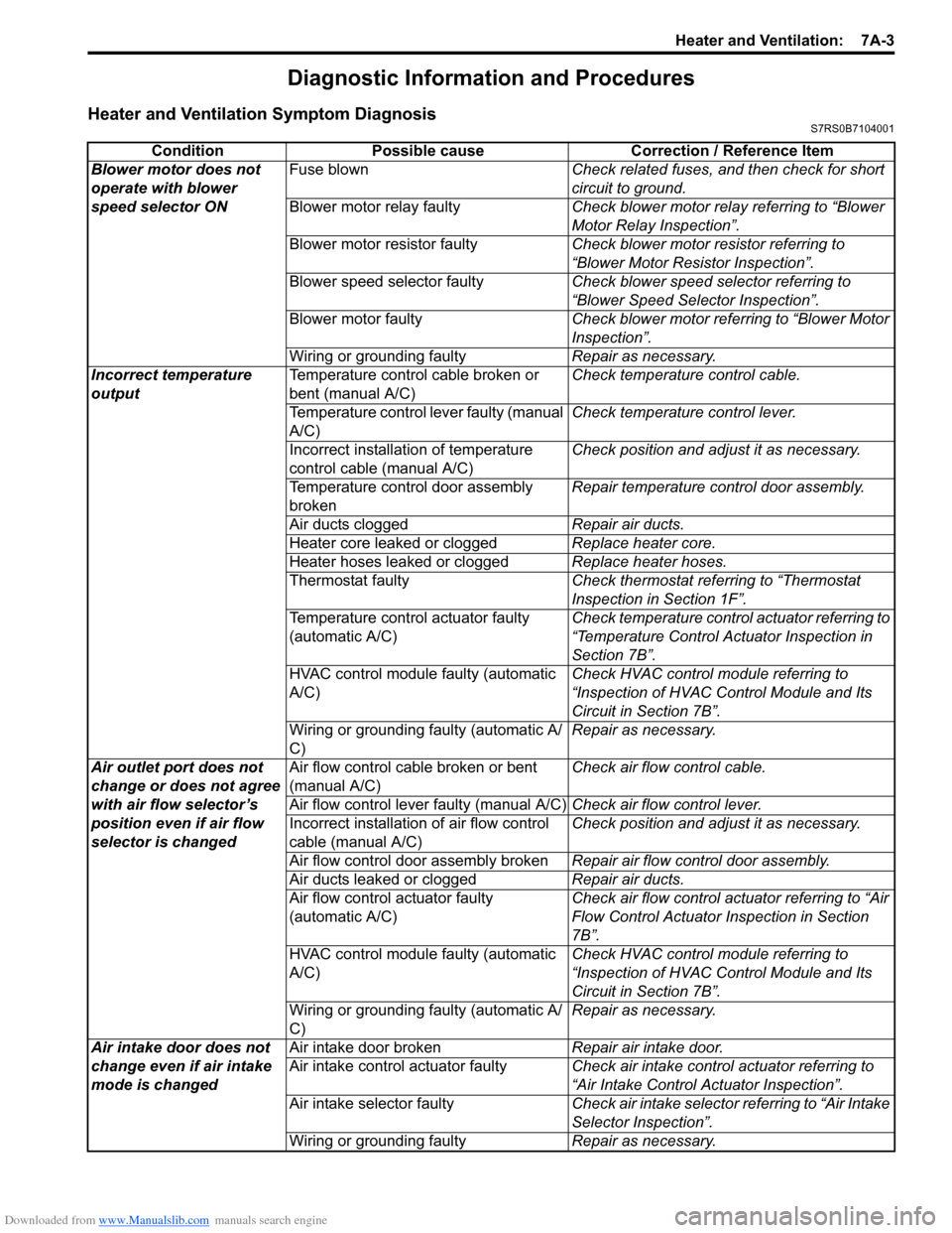
Diagnostic Information and Procedures
Heater and Ventilation Symptom DiagnosisS7RS0B7104001
ConditionPossible cause Correction / Reference Item
Blower motor does not
operate with blower
speed selector ON Fuse blown
Check related fuses, and then check for short
circuit to ground.
Blower motor relay faulty Check blower motor relay referring to “Blower
Motor Relay Inspection”.
Blower motor resistor faulty Check blower motor resistor referring to
“Blower Motor Resistor Inspection”.
Blower speed selector faulty Check blower speed selector referring to
“Blower Speed Selector Inspection”.
Blower motor faulty Check blower motor referring to “Blower Motor
Inspection”.
Wiring or grounding faulty Repair as necessary.
Incorrect temperature
output Temperature control cable broken or
bent (manual A/C) Check temperature control cable.
Temperature control lever faulty (manual
A/C) Check temperature control lever.
Incorrect installation of temperature
control cable (manual A/C) Check position and adjust it as necessary.
Temperature control door assembly
broken Repair temperature control door assembly.
Air ducts clogged Repair air ducts.
Heater core leaked or clogged Replace heater core.
Heater hoses leaked or clogged Replace heater hoses.
Thermostat faulty Check thermostat referring to “Thermostat
Inspection in Section 1F”.
Temperature control actuator faulty
(automatic A/C) Check temperature control actuator referring to
“Temperature Control Actuator Inspection in
Section 7B”.
HVAC control module faulty (automatic
A/C) Check HVAC control module referring to
“Inspection of HVAC Control Module and Its
Circuit in Section 7B”.
Wiring or grounding faulty (automatic A/
C) Repair as necessary.
Air outlet port does not
change or does not agree
with air flow selector’s
position even if air flow
selector is changed Air flow control cable broken or bent
(manual A/C)
Check air flow control cable.
Air flow control lever faulty (manual A/C) Check air flow control lever.
Incorrect installation of air flow control
cable (manual A/C) Check position and adjust it as necessary.
Air flow control door assembly broken Repair air flow control door assembly.
Air ducts leaked or clogged Repair air ducts.
Air flow control actuator faulty
(automatic A/C) Check air flow control actuator referring to “Air
Flow Control Actuator
Inspection in Section
7B”.
HVAC control module faulty (automatic
A/C) Check HVAC control module referring to
“Inspection of HVAC Control Module and Its
Circuit in Section 7B”.
Wiring or grounding faulty (automatic A/
C) Repair as necessary.
Air intake door does not
change even if air intake
mode is changed Air intake door broken
Repair air intake door.
Air intake control actuator faulty Check air intake control actuator referring to
“Air Intake Control Actuator Inspection”.
Air intake selector faulty Check air intake selector referring to “Air Intake
Selector Inspection”.
Wiring or grounding faulty Repair as necessary.
Page 1246 of 1496
Downloaded from www.Manualslib.com manuals search engine 9A-75 Wiring Systems:
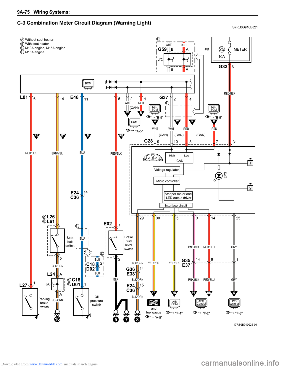
C-3 Combination Meter Circuit Diagram (Warning Light)S7RS0B910E021
J/BMETER
10A25
G2831
3
E24
C3615
G36 E3814
Stepper motor and
LED output driver
Voltage regulator
Interface circuit
Micro controllerEPS
G336
RED/BLK
145293025
PNK/BLKGRY
GRY
RED/BLU
PNK/BLK
BLK/ORN
BLK/ORN
BLK/ORN
RED/BLU
P/S
Cont M
"F-3"
RBPBYBYR
YEL/BLKYEL/RED
A/B
SDM
"F-1""A-5"
ABS
Cont.M
"F-2"
G
CAN
High Low
WHTWHTRED
WHTRED
RED
RW
109 8
6L0114
RED/BLKBRN/YEL
L271
Parking
brake
switch
1
2
A
A
16
BLK/ORN
BLK/ORN
J/C
L24
Seat belt
switch
Oil
pressure switch
E24
C3614
BLU
BLU
1C18
D01
RED/BLK
E021
Brake
fluid
level
switch
and
fuel gauge
2
53
BLK
11 5E46G372
4
RW
W
21WHTRED
"A-5"
1
2
RBBBYRB
7
BCM
ECM"B-9"
KLS
ECM
7
R"B-9"
KLS
ECM
Without seat heater
AWith seat heater
BM13A engine, M15A engine
CM16A engine
D
C
C
C
D
(CAN)
(CAN) (CAN)
(CAN)
L26
L61AB
B
BA
A
J/C
G59
BLU
BLU
D
C18
D022G35 E371419
D
I7RS0B910925-01
Page 1330 of 1496
Downloaded from www.Manualslib.com manuals search engine 9E-3 Glass / Windows / Mirrors:
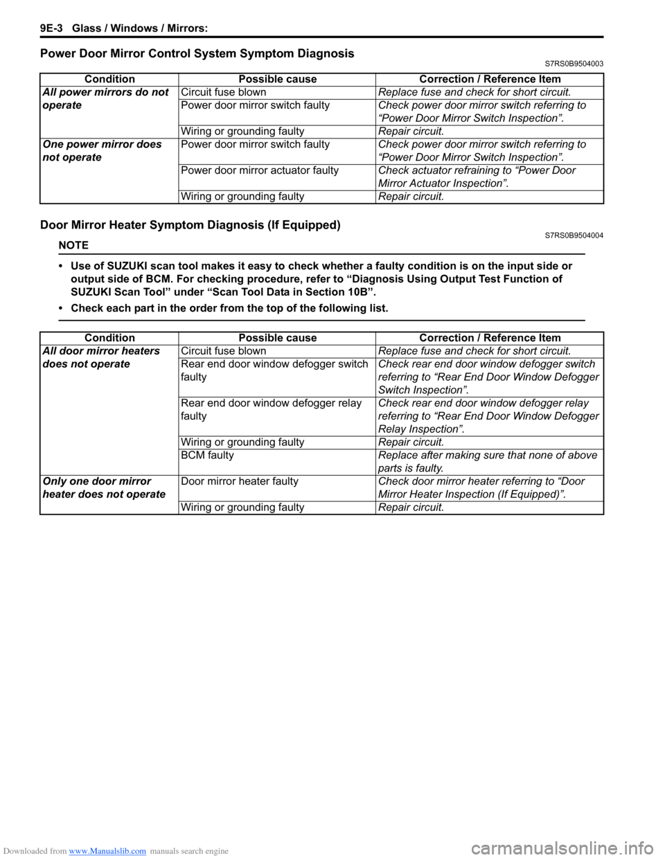
Power Door Mirror Control System Symptom DiagnosisS7RS0B9504003
Door Mirror Heater Symptom Diagnosis (If Equipped)S7RS0B9504004
NOTE
• Use of SUZUKI scan tool makes it easy to check whether a faulty condition is on the input side or
output side of BCM. For checking procedure, re fer to “Diagnosis Using Output Test Function of
SUZUKI Scan Tool” under “Scan Tool Data in Section 10B”.
• Check each part in the order from the top of the following list.
Condition Possible cause Correction / Reference Item
All power mirrors do not
operate Circuit fuse blown
Replace fuse and check for short circuit.
Power door mirror switch faulty Check power door mirror switch referring to
“Power Door Mirror Switch Inspection”.
Wiring or grounding faulty Repair circuit.
One power mirror does
not operate Power door mirror switch faulty
Check power door mirror switch referring to
“Power Door Mirror Switch Inspection”.
Power door mirror actuator faulty Check actuator refraining to “Power Door
Mirror Actuator Inspection”.
Wiring or grounding faulty Repair circuit.
ConditionPossible cause Correction / Reference Item
All door mirror heaters
does not operate Circuit fuse blown
Replace fuse and check for short circuit.
Rear end door window defogger switch
faulty Check rear end door window defogger switch
referring to “Rear End Door Window Defogger
Switch Inspection”.
Rear end door window defogger relay
faulty Check rear end door window defogger relay
referring to “Rear End Door Window Defogger
Relay Inspection”.
Wiring or grounding faulty Repair circuit.
BCM faulty Replace after making sure that none of above
parts is faulty.
Only one door mirror
heater does not operate Door mirror heater faulty
Check door mirror heater referring to “Door
Mirror Heater Inspection (If Equipped)”.
Wiring or grounding faulty Repair circuit.
Page 1404 of 1496
Downloaded from www.Manualslib.com manuals search engine 10B-1 Body Electrical Control System:
Control Systems
Body Electrical Control System
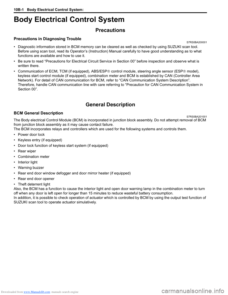
Precautions
Precautions in Diagnosing TroubleS7RS0BA200001
• Diagnostic information stored in BCM memory can be cleared as well as checked by using SUZUKI scan tool.
Before using scan tool, read its Operator ’s (Instruction) Manual carefully to have good understanding as to what
functions are available and how to use it.
• Be sure to read “Precautions for Electrical Circuit Serv ice in Section 00” before inspection and observe what is
written there.
• Communication of ECM, TCM (if equipped), ABS/ESP ® control module, steering angle sensor (ESP ® model),
keyless start control module (if equipped), combinatio n meter and BCM is established by CAN (Controller Area
Network). For detail of CAN communication for BCM, refer to “CAN Communication System Description”.
Therefore, handle CAN communication line with care referr ing to “Precaution for CAN Communication System in
Section 00”.
General Description
BCM General DescriptionS7RS0BA201001
The Body electrical Control Module (BCM) is incorporated in junction block assembly. Do not attempt removal of BCM
from junction block assembly as it may cause contact failure.
The BCM incorporates relays and controllers which are used for the following systems and controls them.
• Power door lock
• Keyless entry (if equipped)
• Door lock function of keyle ss start system (if equipped)
• Rear wiper
• Combination meter
• Interior light
• Warning buzzer
• Rear end door window defogger and door mirror heater (if equipped)
• Rear end door opener
• Theft deterrent light
Also, the BCM has a function to cause the interior light and open door warning lamp in the combination meter to turn
off when any door is left open for longer than 15 minutes to reduce wasteful battery consumption.
In addition, it is possible to check operation of actuator whic h is controlled by BCM by using the output test function of
SUZUKI scan tool to operate actuator simulatively.
Page 1438 of 1496
Downloaded from www.Manualslib.com manuals search engine 10B-35 Body Electrical Control System:
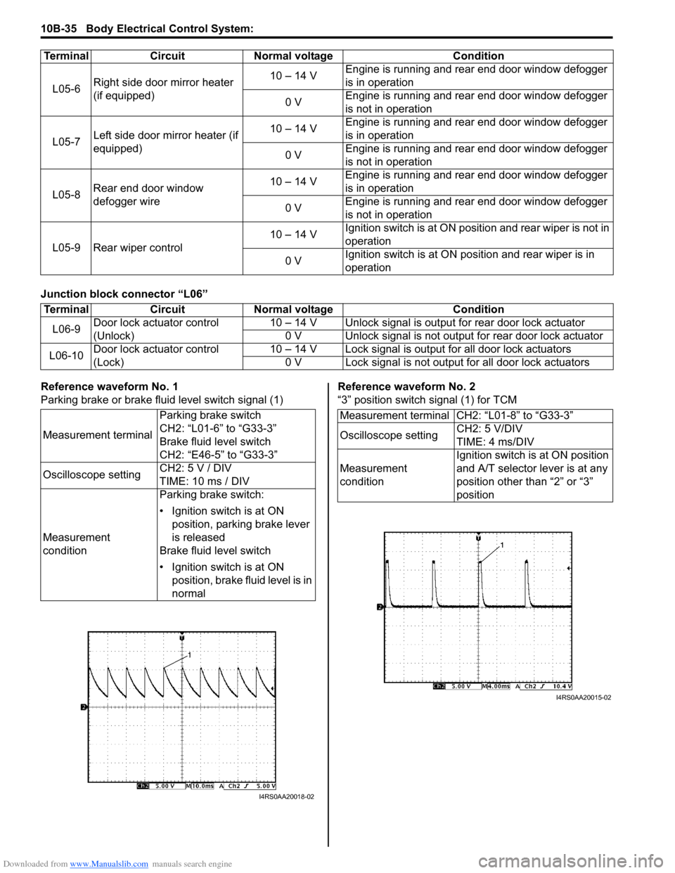
Junction block connector “L06”
Reference waveform No. 1
Parking brake or brake fluid level switch signal (1)Reference waveform No. 2
“3” position switch signal (1) for TCM
L05-6
Right side door mirror heater
(if equipped) 10 – 14 V
Engine is running and rear end door window defogger
is in operation
0 V Engine is running and rear end door window defogger
is not in operation
L05-7 Left side door mirror heater (if
equipped) 10 – 14 V
Engine is running and rear end door window defogger
is in operation
0 V Engine is running and rear end door window defogger
is not in operation
L05-8 Rear end door window
defogger wire 10 – 14 V
Engine is running and rear end door window defogger
is in operation
0 V Engine is running and rear end door window defogger
is not in operation
L05-9 Rear wiper control 10 – 14 V
Ignition switch is at ON posi
tion and rear wiper is not in
operation
0 V Ignition switch is at ON pos
ition and rear wiper is in
operation
Terminal Circuit Normal voltage Condition
Terminal
CircuitNormal voltage Condition
L06-9 Door lock actuator control
(Unlock) 10 – 14 V Unlock signal is outpu
t for rear door lock actuator
0 V Unlock signal is not output for rear door lock actuator
L06-10 Door lock actuator control
(Lock) 10 – 14 V Lock signal is output for all door lock actuators
0 V Lock signal is not output for all door lock actuators
Measurement terminal Parking brake switch
CH2: “L01-6” to “G33-3”
Brake fluid level switch
CH2: “E46-5” to “G33-3”
Oscilloscope setting CH2: 5 V / DIV
TIME: 10 ms / DIV
Measurement
condition Parking brake switch:
• Ignition switch is at ON
position, parking brake lever
is released
Brake fluid level switch
• Ignition switch is at ON position, brake fluid level is in
normal
I4RS0AA20018-02
Measurement terminal CH2: “L01-8” to “G33-3”
Oscilloscope setting CH2: 5 V/DIV
TIME: 4 ms/DIV
Measurement
condition Ignition switch is at ON position
and A/T selector lever is at any
position other than “2” or “3”
position
I4RS0AA20015-02