2007 SUZUKI SWIFT Hazard light
[x] Cancel search: Hazard lightPage 1216 of 1496

Downloaded from www.Manualslib.com manuals search engine 9A-45 Wiring Systems:
System Circuit Diagram
System Circuit DiagramS7RS0B910E001
Refer to “A-1 Cranking System Circuit Diagram”.
Refer to “A-2 Charging System Circuit Diagram”.
Refer to “A-3 Ignition System Circuit Diagram”.
Refer to “A-4 Cooling System Circuit Diagram”.
Refer to “A-5 Engine and A/C Control System Circuit Diagram”.
Refer to “A-6 A/T Control System Circuit Diagram”.
Refer to “A-7 Immobilizer System Circuit Diagram”.
Refer to “A-8 Body Control System Circuit Diagram”.
Refer to “B-1 Windshield Wiper and Washer Circuit Diagram”.
Refer to “B-2 Rear Wiper and Washer Circuit Diagram”.
Refer to “B-3 Rear Defogger Circuit Diagram”.
Refer to “B-4 Power Window Circuit Diagram”.
Refer to “B-5 Power Door Lock Circuit Diagram”.
Refer to “B-6 Power Mi rror Circuit Diagram”.
Refer to “B-7 Horn Circuit Diagram”.
Refer to “B-8 Seat Heater Circuit Diagram”.
Refer to “B-9 Keyless Star t System Circuit Diagram”.
Refer to “C-1 Combination Me ter Circuit Diagram (Meter)”.
Refer to “C-2 Combination Mete r Circuit Diagram (Indicator)”.
Refer to “C-3 Combination Meter Circuit Diagram (Warning Light)”.
Refer to “D-1 Headlight System Circuit Diagram”.
Refer to “D-2 Position, Tail and Licence Plate Light System Circuit Diagram”.
Refer to “D-3 Front Fog Light System Circuit Diagram”.
Refer to “D-4 Illumination Light System Circuit Diagram”.
Refer to “D-5 Interior Li ght System Circuit Diagram”.
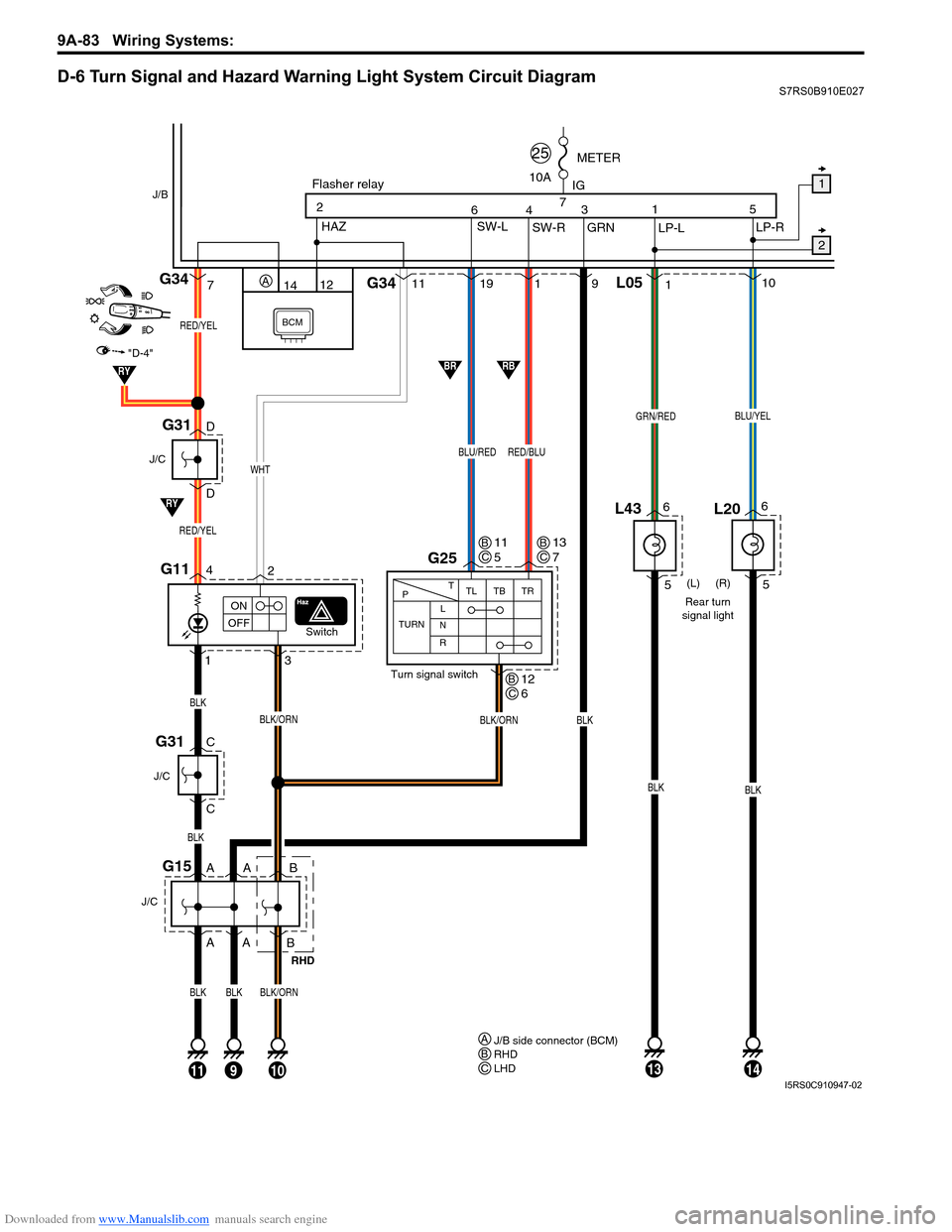
Refer to “D-6 Turn Signal and Hazard Warning Light System Circuit Diagram”.
Refer to “D-7 Brake Light System Circuit Diagram”.
Refer to “D-8 Back-Up Light System Circuit Diagram”.
Refer to “D-9 Headlight Beam Leveling System Circuit Diagram”.
Refer to “D-10 Rear Fog Light Circuit Diagram”.
Refer to “E-1 Heater System Circuit Diagram”.
Refer to “E-2 Auto A/C System Circuit Diagram”.
Refer to “F-1 Air-Bag System Circuit Diagram”.
Refer to “F-2 Anti-Lock Brake System Circuit Diagram”.
Refer to “F-3 Electronic Stabilit y Program System Circuit Diagram”.
Refer to “F-4 Power Steeri ng System Circuit Diagram”.
Refer to “G-1 Audio Sy stem Circuit Diagram”.
Refer to “G-2 Multi Information Display / Accessory Socket System Circuit Diagram”.
Page 1254 of 1496
Downloaded from www.Manualslib.com manuals search engine 9A-83 Wiring Systems:
D-6 Turn Signal and Hazard Warning Light System Circuit DiagramS7RS0B910E027
4 D
DG11G312
Switch
BLK/ORNBLK
WHT
Rear turn
signal light
6L43
BLK
11
2
HAZ LP-LLP-R
Flasher relayG34
RED/YEL
RED/YEL
Turn signal switch
G25
10A
METER
25
RED/BLUBLU/RED
J/B
L
N
R
TURN T
P TB
TL TR
J/C
1110
7G3414A
BCM
12
1
BLK
C
CG31
J/C
ON
OFF
3
A
B
A
AG15
J/C
BLU/YEL
(R)
1
1314
BLK
191L0510
IG
7
6
SW-L SW-R
4
BLK
BLK/ORNBLK/ORN
GRN/RED
(L)
L20
5
6
5
1
2
15
RY
9
GRN
3
BLK
B
RY
"D-4"BRRB
BLK
9
A
J/B side connector (BCM)
RHD
LHD
ABC
BC11
5
BC12
6
BC13
7
RHD
I5RS0C910947-02
Page 1283 of 1496
Downloaded from www.Manualslib.com manuals search engine Lighting Systems: 9B-1
Body, Cab and Accessories
Lighting Systems
Component Location
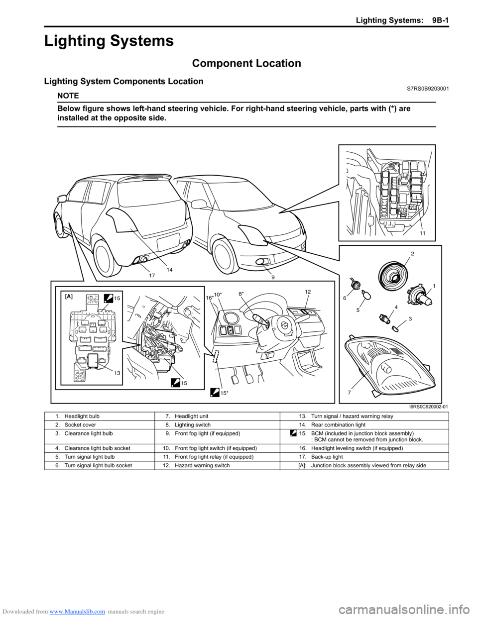
Lighting System Components LocationS7RS0B9203001
NOTE
Below figure shows left-hand steering vehicle. For right-hand steering vehicle, parts with (*) are
installed at the opposite side.
2
1
3
4
6
14
5
7
11
9
15
[A]
1515*
10*
8* 12
13
16*
17
I6RS0C920002-01
1. Headlight bulb 7. Headlight unit 13. Turn signal / hazard warning relay
2. Socket cover 8. Lighting switch 14. Rear combination light
3. Clearance light bulb 9. Front fog light (if equipped)15. BCM (included in junction block assembly)
: BCM cannot be removed from junction block.
4. Clearance light bulb socket 10. Front fog light switch (if equipped) 16. Headlight leveling switch (if equipped)
5. Turn signal light bulb 11. Front fog light relay (if equipped) 17. Back-up light
6. Turn signal light bulb socket 12. Hazard warning switch [A]: Junction block assembly viewed from relay side
Page 1285 of 1496
Downloaded from www.Manualslib.com manuals search engine Lighting Systems: 9B-3
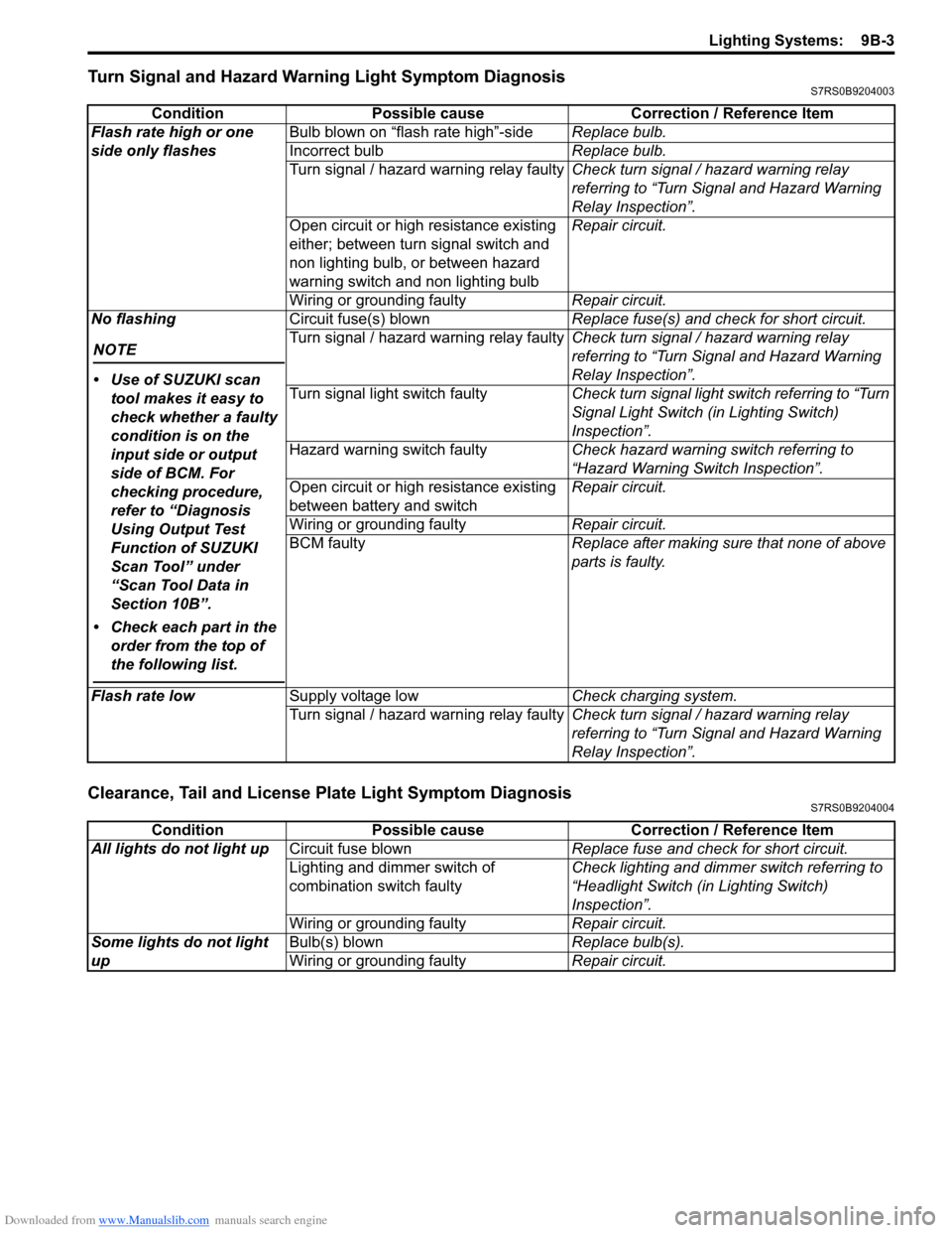
Turn Signal and Hazard Warning Light Symptom DiagnosisS7RS0B9204003
Clearance, Tail and License Plate Light Symptom DiagnosisS7RS0B9204004
ConditionPossible cause Correction / Reference Item
Flash rate high or one
side only flashes Bulb blown on “flash rate high”-side
Replace bulb.
Incorrect bulb Replace bulb.
Turn signal / hazard warning relay faulty Check turn signal / hazard warning relay
referring to “Turn Signal and Hazard Warning
Relay Inspection”.
Open circuit or high resistance existing
either; between turn signal switch and
non lighting bulb, or between hazard
warning switch and non lighting bulb Repair circuit.
Wiring or grounding faulty Repair circuit.
No flashing
NOTE
• Use of SUZUKI scan tool makes it easy to
check whether a faulty
condition is on the
input side or output
side of BCM. For
checking procedure,
refer to “Diagnosis
Using Output Test
Function of SUZUKI
Scan Tool” under
“Scan Tool Data in
Section 10B”.
• Check each part in the order from the top of
the following list.
Circuit fuse(s) blown Replace fuse(s) and check for short circuit.
Turn signal / hazard warning relay faulty Check turn signal / hazard warning relay
referring to “Turn Signal and Hazard Warning
Relay Inspection”.
Turn signal light switch faulty Check turn signal light switch referring to “Turn
Signal Light Switch (in Lighting Switch)
Inspection”.
Hazard warning switch faulty Check hazard warning switch referring to
“Hazard Warning Switch Inspection”.
Open circuit or high resistance existing
between battery and switch Repair circuit.
Wiring or grounding faulty Repair circuit.
BCM faulty Replace after making sure that none of above
parts is faulty.
Flash rate low Supply voltage low Check charging system.
Turn signal / hazard warning relay faulty Check turn signal / hazard warning relay
referring to “Turn Signal and Hazard Warning
Relay Inspection”.
ConditionPossible cause Correction / Reference Item
All lights do not light up Circuit fuse blown Replace fuse and check for short circuit.
Lighting and dimmer switch of
combination switch faulty Check lighting and dimmer switch referring to
“Headlight Switch (in Lighting Switch)
Inspection”.
Wiring or grounding faulty Repair circuit.
Some lights do not light
up Bulb(s) blown
Replace bulb(s).
Wiring or grounding faulty Repair circuit.
Page 1290 of 1496
Downloaded from www.Manualslib.com manuals search engine 9B-8 Lighting Systems:
Headlight Switch (in Lighting Switch) Removal
and Installation
S7RS0B9206004
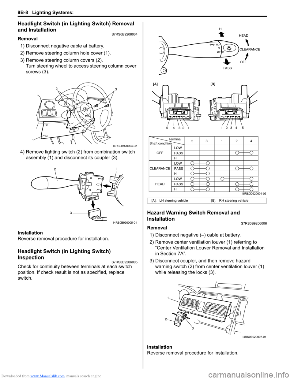
Removal1) Disconnect negative cable at battery.
2) Remove steering column hole cover (1).
3) Remove steering column covers (2). Turn steering wheel to acce ss steering column cover
screws (3).
4) Remove lighting switch (2 ) from combination switch
assembly (1) and disconnect its coupler (3).
Installation
Reverse removal procedure for installation.
Headlight Switch (in Lighting Switch)
Inspection
S7RS0B9206005
Check for continuity between terminals at each switch
position. If check result is not as specified, replace
switch.
Hazard Warning Switch Removal and
Installation
S7RS0B9206006
Removal 1) Disconnect negative (–) cable at battery.
2) Remove center ventilation louver (1) referring to
“Center Ventilation Louver Removal and Installation
in Section 7A”.
3) Disconnect coupler, and then remove hazard warning switch (2) from center ventilation louver (1)
while releasing the locks (3).
Installation
Reverse removal procedure for installation.
1
32
I4RS0B920004-02
1
2
3
I4RS0B920005-01
[A]: LH steering vehicle [B]: RH steering vehicle
Terminal
Shaft condition
OFF 5
3124
LOW
PASS
HI
LOW
PASS
HI LOW
PASS
HI
CLEARANCE
HEAD
HEADCLEARANCE
OFF
HI
PA S S
54321
54321
[A][B]
I5RS0D920004-02
1
2 3
I4RS0B920007-01
Page 1291 of 1496
Downloaded from www.Manualslib.com manuals search engine Lighting Systems: 9B-9
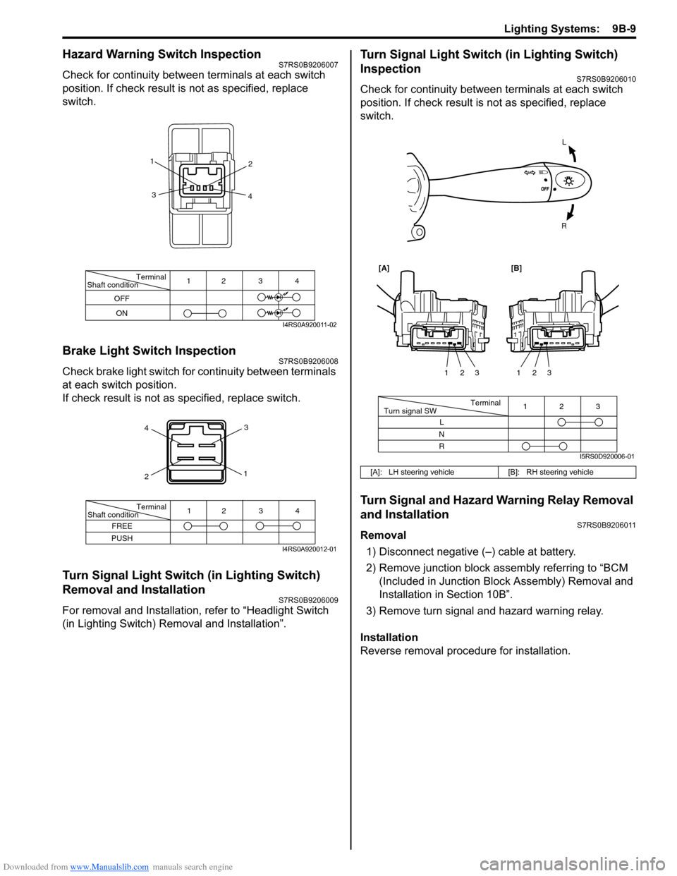
Hazard Warning Switch InspectionS7RS0B9206007
Check for continuity between terminals at each switch
position. If check result is not as specified, replace
switch.
Brake Light Switch InspectionS7RS0B9206008
Check brake light switch for continuity between terminals
at each switch position.
If check result is not as specified, replace switch.
Turn Signal Light Switch (in Lighting Switch)
Removal and Installation
S7RS0B9206009
For removal and Installation, refer to “Headlight Switch
(in Lighting Switch) Removal and Installation”.
Turn Signal Light Switch (in Lighting Switch)
Inspection
S7RS0B9206010
Check for continuity between terminals at each switch
position. If check result is not as specified, replace
switch.
Turn Signal and Hazard Warning Relay Removal
and Installation
S7RS0B9206011
Removal
1) Disconnect negative (–) cable at battery.
2) Remove junction block assembly referring to “BCM (Included in Junction Bl ock Assembly) Removal and
Installation in Section 10B”.
3) Remove turn signal and hazard warning relay.
Installation
Reverse removal procedure for installation.
Terminal
Shaft condition
OFF
ON 12 3 4
1
2
3 4
I4RS0A920011-02
4
2 3
1
Terminal
Shaft condition
FREE
PUSH 12 3 4
I4RS0A920012-01
[A]: LH steering vehicle
[B]: RH steering vehicle
L
R
Terminal
Turn signal SW 3
12
L
N
R 123
123
[A][B]
I5RS0D920006-01
Page 1292 of 1496
Downloaded from www.Manualslib.com manuals search engine 9B-10 Lighting Systems:
Turn Signal and Hazard Warning Relay
Inspection
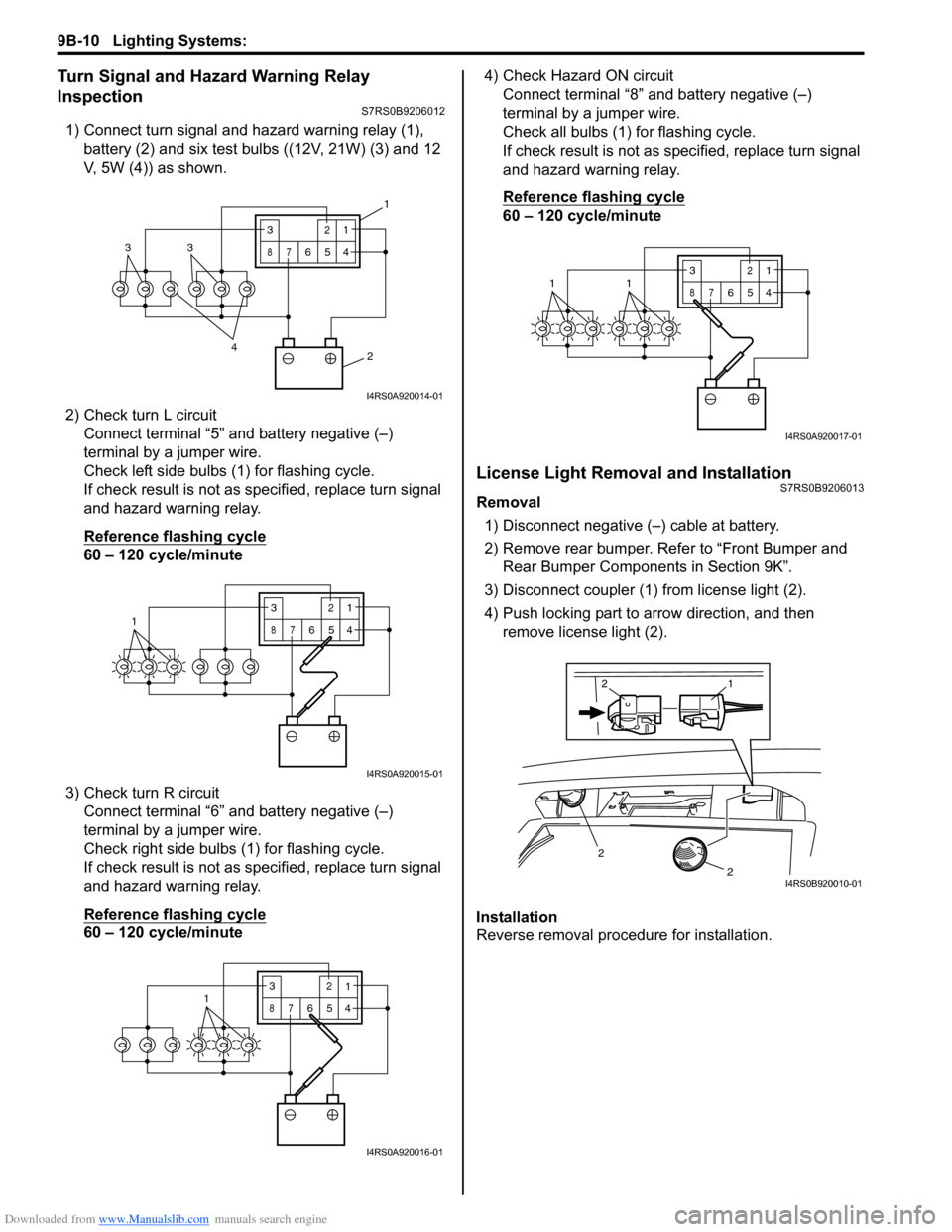
S7RS0B9206012
1) Connect turn signal and hazard warning relay (1), battery (2) and six test bulbs ((12V, 21W) (3) and 12
V, 5W (4)) as shown.
2) Check turn L circuit Connect terminal “5” and battery negative (–)
terminal by a jumper wire.
Check left side bulbs (1) for flashing cycle.
If check result is not as specified, replace turn signal
and hazard warning relay.
Reference flashing cycle
60 – 120 cycle/minute
3) Check turn R circuit Connect terminal “6” and battery negative (–)
terminal by a jumper wire.
Check right side bulbs (1) for flashing cycle.
If check result is not as specified, replace turn signal
and hazard warning relay.
Reference flashing cycle
60 – 120 cycle/minute 4) Check Hazard ON circuit
Connect terminal “8” and battery negative (–)
terminal by a jumper wire.
Check all bulbs (1) for flashing cycle.
If check result is not as sp ecified, replace turn signal
and hazard warning relay.
Reference flashing cycle
60 – 120 cycle/minute
License Light Removal and InstallationS7RS0B9206013
Removal
1) Disconnect negative (–) cable at battery.
2) Remove rear bumper. Refe r to “Front Bumper and
Rear Bumper Components in Section 9K”.
3) Disconnect coupler (1) from license light (2).
4) Push locking part to arrow direction, and then remove license light (2).
Installation
Reverse removal procedure for installation.
2
4
33
3
87
12
654
1
I4RS0A920014-01
13
87
12
654
I4RS0A920015-01
3
87
12
6541
I4RS0A920016-01
3
87
12
6
5411
I4RS0A920017-01
2
2
1
2
I4RS0B920010-01
Page 1300 of 1496
Downloaded from www.Manualslib.com manuals search engine 9C-5 Instrumentation / Driver Info. / Horn:
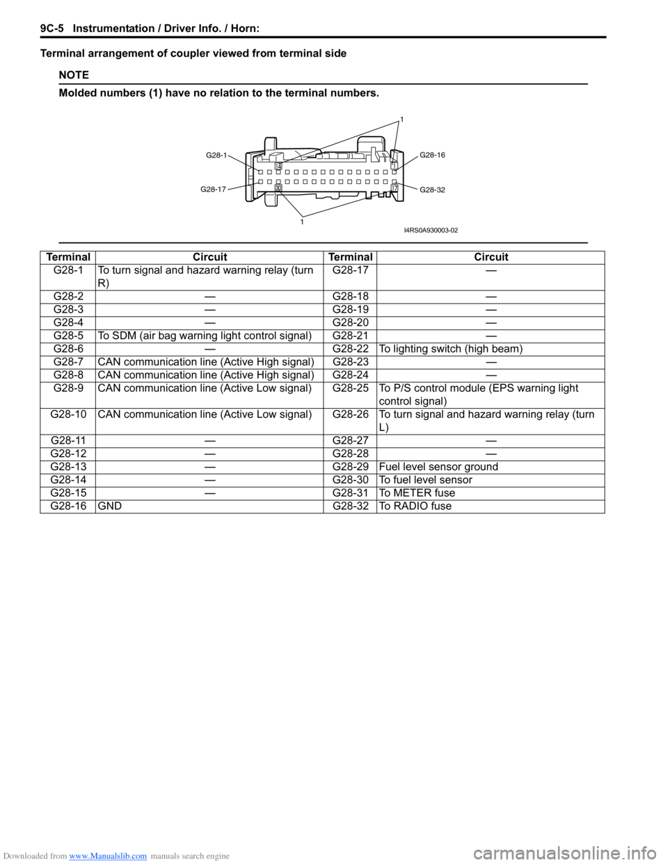
Terminal arrangement of coupler viewed from terminal side
NOTE
Molded numbers (1) have no relation to the terminal numbers.
TerminalCircuitTerminal Circuit
G28-1 To turn signal and hazard warning relay (turn R) G28-17
—
G28-2 —G28-18 —
G28-3 —G28-19 —
G28-4 —G28-20 —
G28-5 To SDM (air bag warning light control signal) G28-21 —
G28-6 —G28-22 To lighting switch (high beam)
G28-7 CAN communication line (Active High signal) G28-23 —
G28-8 CAN communication line (Active High signal) G28-24 —
G28-9 CAN communication line (Active Low signal) G 28-25 To P/S control module (EPS warning light
control signal)
G28-10 CAN communication line (Active Low signal) G28-26 To turn signal and hazard warning relay (turn L)
G28-11 —G28-27 —
G28-12 —G28-28 —
G28-13 —G28-29 Fuel level sensor ground
G28-14 —G28-30 To fuel level sensor
G28-15 —G28-31 To METER fuse
G28-16 GND G28-32 To RADIO fuse
G28-1 G28-16
G28-32
G28-17
1 1I4RS0A930003-02