2007 SUZUKI SWIFT Brake fluid level inspection
[x] Cancel search: Brake fluid level inspectionPage 605 of 1496
Downloaded from www.Manualslib.com manuals search engine Electronic Stability Program: 4F-31
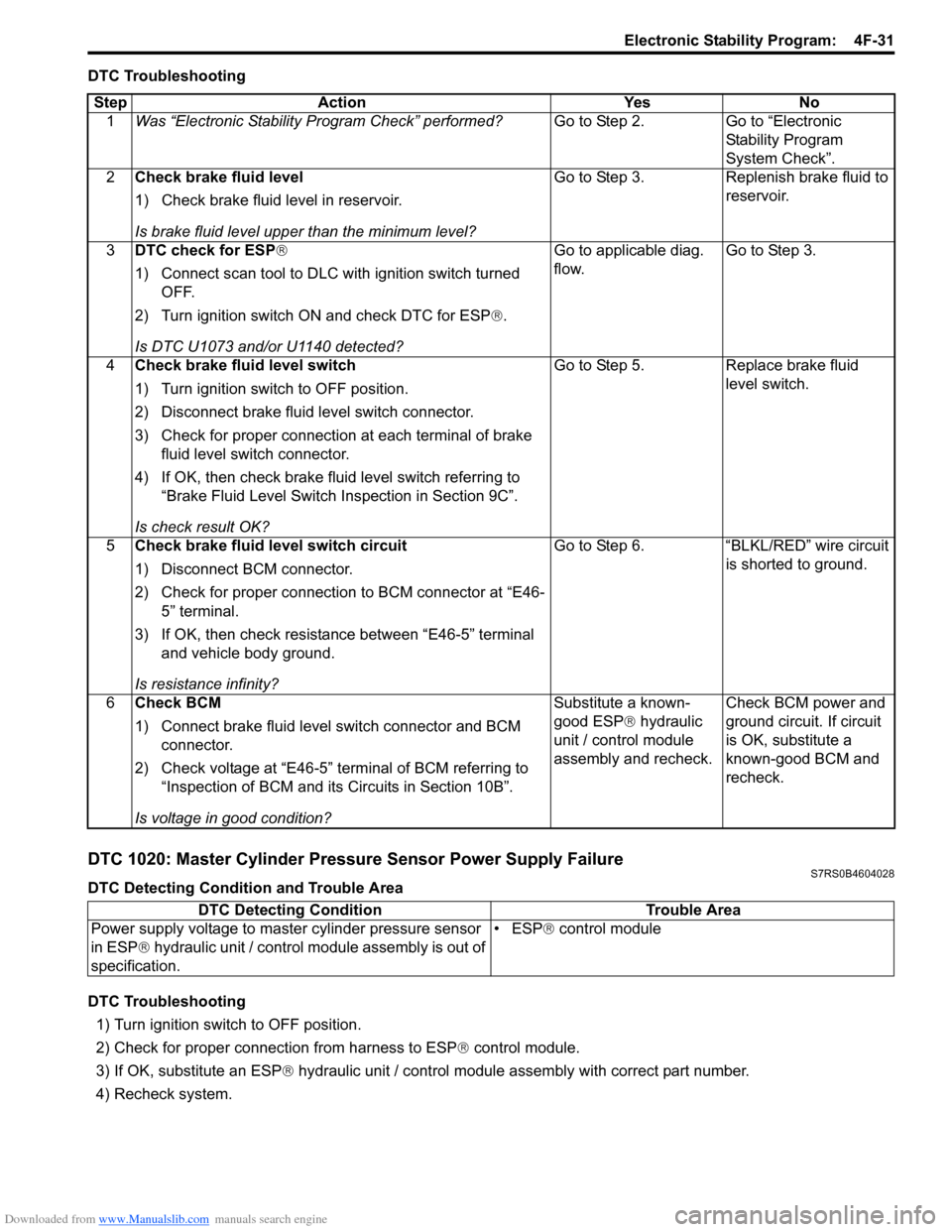
DTC Troubleshooting
DTC 1020: Master Cylinder Pressure Sensor Power Supply FailureS7RS0B4604028
DTC Detecting Condition and Trouble Area
DTC Troubleshooting1) Turn ignition switch to OFF position.
2) Check for proper connection from harness to ESP ® control module.
3) If OK, substitute an ESP ® hydraulic unit / control module assembly with correct part number.
4) Recheck system.
Step Action Yes No
1 Was “Electronic Stability Pr ogram Check” performed? Go to Step 2. Go to “Electronic
Stability Program
System Check”.
2 Check brake fluid level
1) Check brake fluid level in reservoir.
Is brake fluid level upper than the minimum level? Go to Step 3. Replenish brake fluid to
reservoir.
3 DTC check for ESP®
1) Connect scan tool to DLC with ignition switch turned
OFF.
2) Turn ignition switch ON and check DTC for ESP ®.
Is DTC U1073 and/or U1140 detected? Go to applicable diag.
flow.
Go to Step 3.
4 Check brake fluid level switch
1) Turn ignition switch to OFF position.
2) Disconnect brake fluid level switch connector.
3) Check for proper connection at each terminal of brake
fluid level switch connector.
4) If OK, then check brake fluid level switch referring to “Brake Fluid Level Switch Inspection in Section 9C”.
Is check result OK? Go to Step 5. Replace brake fluid
level switch.
5 Check brake fluid level switch circuit
1) Disconnect BCM connector.
2) Check for proper connection to BCM connector at “E46-
5” terminal.
3) If OK, then check resistance between “E46-5” terminal and vehicle body ground.
Is resistance infinity? Go to Step 6. “BLKL/RED” wire circuit
is shorted to ground.
6 Check BCM
1) Connect brake fluid level switch connector and BCM
connector.
2) Check voltage at “E46-5” terminal of BCM referring to “Inspection of BCM and its Circuits in Section 10B”.
Is voltage in good condition? Substitute a known-
good ESP
® hydraulic
unit / control module
assembly and recheck. Check BCM power and
ground circuit. If circuit
is OK, substitute a
known-good BCM and
recheck.
DTC Detecting Condition
Trouble Area
Power supply voltage to master cylinder pressure sensor
in ESP® hydraulic unit / control mo dule assembly is out of
specification. • ESP
® control module
Page 629 of 1496
Downloaded from www.Manualslib.com manuals search engine Electronic Stability Program: 4F-55
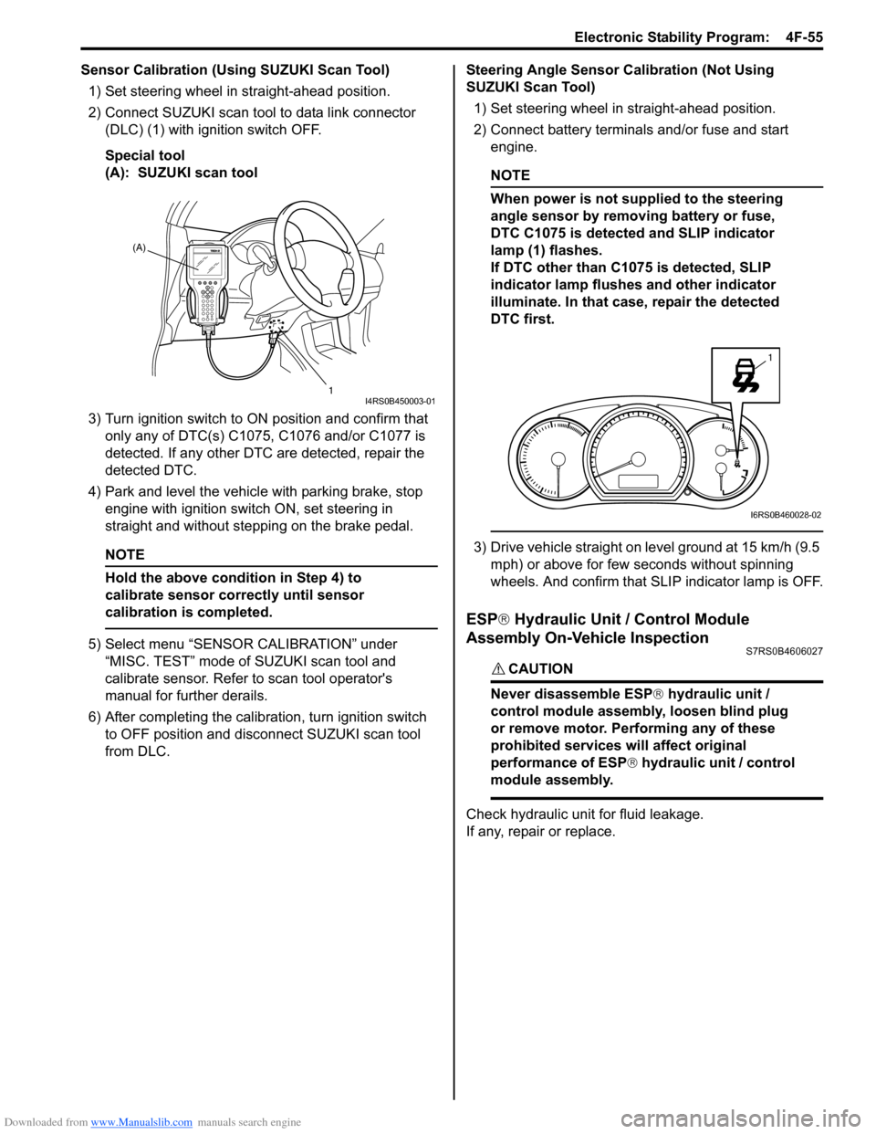
Sensor Calibration (Using SUZUKI Scan Tool)1) Set steering wheel in straight-ahead position.
2) Connect SUZUKI scan tool to data link connector (DLC) (1) with ignition switch OFF.
Special tool
(A): SUZUKI scan tool
3) Turn ignition switch to ON position and confirm that
only any of DTC(s) C1075, C1076 and/or C1077 is
detected. If any other DTC are detected, repair the
detected DTC.
4) Park and level the vehicle with parking brake, stop engine with ignition switch ON, set steering in
straight and without step ping on the brake pedal.
NOTE
Hold the above condition in Step 4) to
calibrate sensor correctly until sensor
calibration is completed.
5) Select menu “SENSOR CALIBRATION” under
“MISC. TEST” mode of SUZUKI scan tool and
calibrate sensor. Refer to scan tool operator's
manual for further derails.
6) After completing the calibra tion, turn ignition switch
to OFF position and disconnect SUZUKI scan tool
from DLC. Steering Angle Sensor Calibration (Not Using
SUZUKI Scan Tool)
1) Set steering wheel in straight-ahead position.
2) Connect battery terminals and/or fuse and start engine.
NOTE
When power is not supplied to the steering
angle sensor by removing battery or fuse,
DTC C1075 is detected and SLIP indicator
lamp (1) flashes.
If DTC other than C1075 is detected, SLIP
indicator lamp flushes and other indicator
illuminate. In that case, repair the detected
DTC first.
3) Drive vehicle straight on level ground at 15 km/h (9.5 mph) or above for few seconds without spinning
wheels. And confirm that SLIP indicator lamp is OFF.
ESP ® Hydraulic Unit / Control Module
Assembly On-Vehicle Inspection
S7RS0B4606027
CAUTION!
Never disassemble ESP ® hydraulic unit /
control module assembly, loosen blind plug
or remove motor. Pe rforming any of these
prohibited services will affect original
performance of ESP ® hydraulic unit / control
module assembly.
Check hydraulic unit for fluid leakage.
If any, repair or replace.
(A)
1
I4RS0B450003-01
1
I6RS0B460028-02
Page 642 of 1496

Downloaded from www.Manualslib.com manuals search engine 5-ii Table of Contents
DTC P1878: Torque Converter Clutch Shudder .......................................................... 5A-75
DTC P2762: Torque Converter Clutch (TCC) Pressure Control Sole noid Control Circuit
Range /Performance ....................................... 5A-76
DTC P2763: Torque Converter Clutch Pressure Control Sole noid Control Circuit
High ................................................................. 5A-78
DTC P2764: Torque Converter Clutch Circuit Pressure Control Sole noid Control Circuit
Low ................................................................. 5A-80
Inspection of TCM and Its Circuits .................... 5A-82
TCM Power and Ground Circuit Check ............. 5A-86
Brake Interlock System Inspection .................... 5A-87
Repair Instructions ........... .................................5A-88
Learning Control Initializat ion ............................ 5A-88
A/T Fluid Level Check ....................................... 5A-89
A/T Fluid Change .............................................. 5A-90
Select Lever Components ... .............................. 5A-90
Select Lever Assembly Removal and Installation ....................................................... 5A-90
Select Lever Knob Installa tion........................... 5A-90
Select Lever Inspection .... ................................. 5A-91
“3” Position Switch Inspec tion ........................... 5A-91
Shift Lock Solenoid Inspec tion .......................... 5A-91
Shift Lock Solenoid Replacement ..................... 5A-91
Select Cable Components ................................ 5A-92
Select Cable Removal and Installation ............. 5A-92
Select Cable Adjustment ................................... 5A-93
Key Interlock Cable Removal and Installation... 5A-93
Transmission Range Sensor (Shift Switch) Inspection and Adjustment .............................. 5A-95
Output Shaft Speed Sensor Removal and Installation ....................................................... 5A-96
Output Shaft Speed Sensor Inspection ............. 5A-96
Input Shaft Speed Sensor Removal and Installation ....................................................... 5A-96
Input Shaft Speed Sensor Inspection................ 5A-97
Transmission Fluid Temperature Sensor Removal and Installation ................................. 5A-97
Transmission Fluid Temperature Sensor Inspection ........................................................ 5A-98
Solenoid Valves (Shift Solenoid Valves and Timing Solenoid Valve) Removal and
Installation ....................................................... 5A-98
Solenoid Valves (Shift Solenoid Valves, and Timing Solenoid Valve) Inspection .................. 5A-99
Pressure Control Soleno id Valves (Pressure
Control Solenoid and TCC Pressure Control
Solenoid) Removal and Inst allation .............. 5A-101
Pressure Control Solenoid Valve Inspection ... 5A-101
Transmission Control Module (TCM) Removal and Installation ............................... 5A-102
A/T Relay Inspection ....................................... 5A-103
Differential Side Oil Seal Replacement ........... 5A-103
A/T Fluid Cooler Hoses Replacement ............. 5A-104
Automatic Transaxle Unit Components........... 5A-105
Automatic Transaxle Unit Dismounting and Remounting ................................................... 5A-106
Automatic Transaxle Asse mbly Components . 5A-108 Automatic Transaxle Unit
Disassembly........... 5A-110
Oil Pump Assembly Components ................... 5A-121
Oil Pump Assembly Disassembly and Reassembly .................................................. 5A-122
Oil Pump Assembly Inspection ....................... 5A-122
Direct Clutch Assembly Components.............. 5A-124
Direct Clutch Assembly Preliminary Check ..... 5A-124
Direct Clutch Assembly Disassembly and Reassembly .................................................. 5A-125
Direct Clutch Assembly Inspection.................. 5A-127
Forward and Reverse Clutch Assembly Components .................................................. 5A-128
Forward and Reverse Clutch Assembly Preliminary Check ......................................... 5A-129
Forward and Reverse Clutch Assembly Disassembly and Reassembly ...................... 5A-129
Forward and Reverse Clutch Assembly Inspection ...................................................... 5A-133
2nd Brake Piston Assembly Components ....... 5A-134
2nd Brake Piston Assembly Disassembly and Reassembly .................................................. 5A-134
Transaxle Rear Cover (O/D and 2nd Coast Brake Piston) Assembly Components........... 5A-135
Transaxle Rear Cover (O/D and 2nd Coast Brake Piston) Assembly Disassembly and
Reassembly .................................................. 5A-136
Transaxle Rear Cover (O/D and 2nd Coast Brake Piston) Assembly Inspection............... 5A-137
Countershaft Assembly Co mponents.............. 5A-138
Countershaft Assembly Disassembly and Reassembly .................................................. 5A-138
Valve Body Assembly Components ................ 5A-139
Valve Body Assembly Disassembly and Reassembly .................................................. 5A-140
Differential Assembly Components ................. 5A-141
Differential Assembly Disassembly and Reassembly .................................................. 5A-142
Differential Assembly Inspection ..................... 5A-143
Torque Converter Housing Disassembly and Reassembly .................................................. 5A-144
Transaxle Case Disassembly and Reassembly .................................................. 5A-146
Automatic Transaxle Unit Inspection and Adjus
tment .................................................... 5A-147
Automatic Transaxle Unit Assembly ............... 5A-150
Specifications .................. .................................5A-167
Tightening Torque Specifications .................... 5A-167
Special Tools and Equipmen t .........................5A-168
Recommended Service Material ..................... 5A-168
Special Tool .................................................... 5A-168
Manual Transmission/Tr ansaxle ............ 5B-1
General Description .............................................5B-1
Manual Transaxle Construction and Servicing .... 5B-1
Diagnostic Information and Procedures ............5B-3 Manual Transaxle Symptom Diagnosis............... 5B-3
Repair Instructions ............ ..................................5B-3
Manual Transaxle Oil Change............................. 5B-3
Differential Side Oil Seal Replacement ............... 5B-4
Page 686 of 1496
Downloaded from www.Manualslib.com manuals search engine 5A-42 Automatic Transmission/Transaxle:
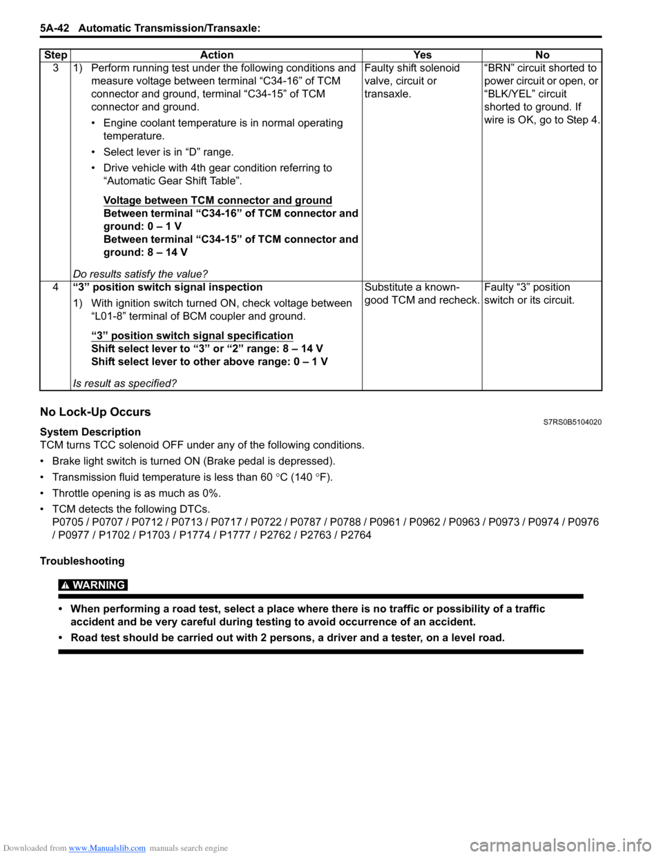
No Lock-Up OccursS7RS0B5104020
System Description
TCM turns TCC solenoid OFF under any of the following conditions.
• Brake light switch is turned ON (Brake pedal is depressed).
• Transmission fluid temperat ure is less than 60 °C (140 °F).
• Throttle opening is as much as 0%.
• TCM detects the following DTCs. P0705 / P0707 / P0712 / P0713 / P0717 / P0722 / P0787 / P0788 / P0961 / P0962 / P0963 / P0973 / P0974 / P0976
/ P0977 / P1702 / P1703 / P1774 / P1777 / P2762 / P2763 / P2764
Troubleshooting
WARNING!
• When performing a road test, select a place where there is no traffic or possibility of a traffic accident and be very careful during testing to avoid occurrence of an accident.
• Road test should be carried out with 2 persons, a driver and a tester, on a level road.
3 1) Perform running test under the following conditions and measure voltage between terminal “C34-16” of TCM
connector and ground, terminal “C34-15” of TCM
connector and ground.
• Engine coolant temperature is in normal operating temperature.
• Select lever is in “D” range.
• Drive vehicle with 4th gear condition referring to “Automatic Gear Shift Table”.
Voltage between TCM connector and ground
Between terminal “C34-16” of TCM connector and
ground: 0 – 1 V
Between terminal “C34-15” of TCM connector and
ground: 8 – 14 V
Do results satisfy the value? Faulty shift solenoid
valve, circuit or
transaxle.
“BRN” circuit shorted to
power circuit or open, or
“BLK/YEL” circuit
shorted to ground. If
wire is OK, go to Step 4.
4 “3” position switch signal inspection
1) With ignition switch turned ON, check voltage between
“L01-8” terminal of BCM coupler and ground.
“3” position switch signal specification
Shift select lever to “3” or “2” range: 8 – 14 V
Shift select lever to other above range: 0 – 1 V
Is result as specified? Substitute a known-
good TCM and recheck.
Faulty “3” position
switch or its circuit.
Step Action Yes No
Page 855 of 1496
Downloaded from www.Manualslib.com manuals search engine Clutch: 5C-3
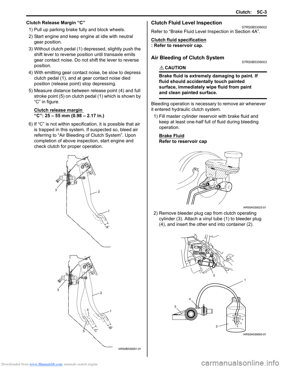
Clutch Release Margin “C”1) Pull up parking brake fully and block wheels.
2) Start engine and keep engine at idle with neutral gear position.
3) Without clutch pedal (1) dep ressed, slightly push the
shift lever to re verse position until transaxle emits
gear contact noise. Do not shift the lever to reverse
position.
4) With emitting gear contact noise, be slow to depress clutch pedal (1), and at gear contact noise died
position (release point) stop depressing.
5) Measure distance between release point (4) and full stroke point (5) on clutch pedal (1) which is shown by
“C” in figure.
Clutch release margin
“C”: 25 – 55 mm (0.98 – 2.17 in.)
6) If “C” is not within specificat ion, it is possible that air
is trapped in this system. If suspected so, bleed air
referring to “Air Bleeding of Clutch System”. Upon
completion of above inspection, start engine and
check clutch for proper operation.
Clutch Fluid Level InspectionS7RS0B5306002
Refer to “Brake Fluid Level Inspection in Section 4A”.
Clutch fluid specification
: Refer to reservoir cap.
Air Bleeding of Clutch SystemS7RS0B5306003
CAUTION!
Brake fluid is extremely damaging to paint. If
fluid should accidentally touch painted
surface, immediately wipe fluid from paint
and clean painted surface.
Bleeding operation is necessary to remove air whenever
it entered hydraulic clutch system.
1) Fill master cylinder reservoir with brake fluid and keep at least one-half full of fluid during bleeding
operation.
Brake Fluid
Refer to reservoir cap
2) Remove bleeder plug cap from clutch operating cylinder (3). Attach a vinyl tube (1) to bleeder plug
(4), and insert the other end into container (2).
2
1
“A”
3
2
1
3
“B”
“C”
4
5
I4RS0B530001-01
I4RS0A530023-01
3 4 1
2
3
I4RS0A530003-01
Page 858 of 1496
Downloaded from www.Manualslib.com manuals search engine 5C-6 Clutch:
Clutch Fluid Pipe Removal and InstallationS7RS0B5306007
Removal
CAUTION!
Do not allow fluid to get on painted surface. It
may cause painted surface damage.
1) Remove dust and dirt from each joint of pipe to be disconnected and clean around brake master
cylinder reservoir cap.
2) Take out fluid with syringe or such from brake master cylinder reservoir.
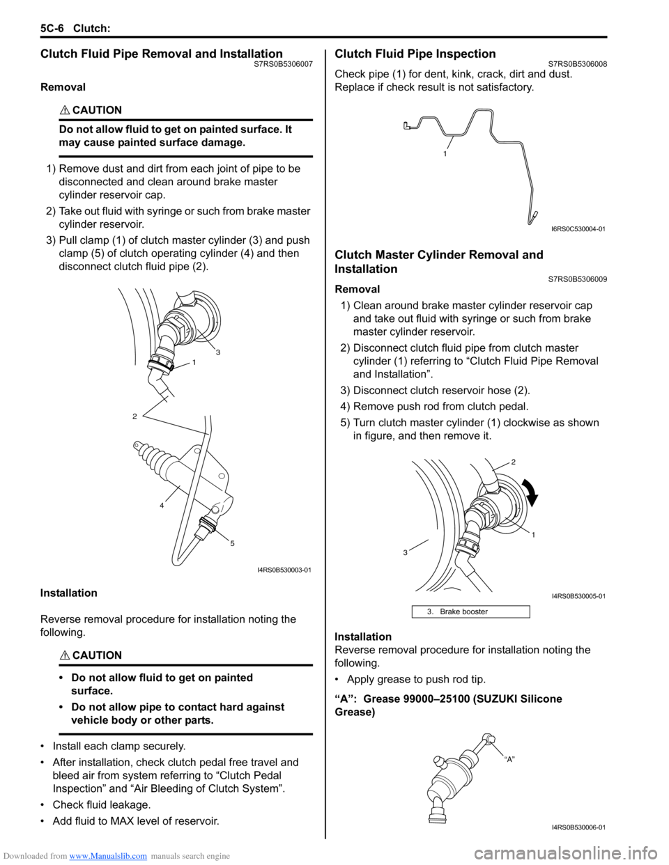
3) Pull clamp (1) of clutch master cylinder (3) and push clamp (5) of clutch operating cylinder (4) and then
disconnect clutch fluid pipe (2).
Installation
Reverse removal procedure for installation noting the
following.
CAUTION!
• Do not allow fluid to get on painted surface.
• Do not allow pipe to contact hard against vehicle body or other parts.
• Install each clamp securely.
• After installation, check clutch pedal free travel and bleed air from system referring to “Clutch Pedal
Inspection” and “Air Blee ding of Clutch System”.
• Check fluid leakage.
• Add fluid to MAX level of reservoir.
Clutch Fluid Pipe InspectionS7RS0B5306008
Check pipe (1) for dent, kink, crack, dirt and dust.
Replace if check result is not satisfactory.
Clutch Master Cylinder Removal and
Installation
S7RS0B5306009
Removal 1) Clean around brake master cylinder reservoir cap and take out fluid with syringe or such from brake
master cylinder reservoir.
2) Disconnect clutch fluid pipe from clutch master cylinder (1) referring to “C lutch Fluid Pipe Removal
and Installation”.
3) Disconnect clutch reservoir hose (2).
4) Remove push rod from clutch pedal.
5) Turn clutch master cylinder (1) clockwise as shown in figure, and then remove it.
Installation
Reverse removal procedure for installation noting the
following.
• Apply grease to push rod tip.
“A”: Grease 99000–25100 (SUZUKI Silicone
Grease)
31
2
5
4
I4RS0B530003-01
3. Brake booster
1
I6RS0C530004-01
1
2
3
I4RS0B530005-01
“A”
I4RS0B530006-01
Page 1168 of 1496

Downloaded from www.Manualslib.com manuals search engine 9-ii Table of Contents
List of Connectors ........................................... 9A-103
C Connector .................................................... 9A-103
D Connector (M16A engine) ........................... 9A-104
E Connector .................................................... 9A-104
G Connector .................................................... 9A-106
J Connector ..................................................... 9A-108
K Connector .................................................... 9A-109
L Connector..................................................... 9A-109
M Connector (SPORT model) ......................... 9A-111
O Connector .................................................... 9A-111
R Connector .................................................... 9A-111
Lighting Systems .................................... 9B-1
Component Location ........... ................................9B-1
Lighting System Component s Location............... 9B-1
Interior Light System Location............................. 9B-2
Diagnostic Information and Procedures ............ 9B-2 Headlight Symptom Diagnosis ............................ 9B-2
Headlight Leveling System Symptom Diagnosis (If Equipped) ..................................... 9B-2
Turn Signal and Hazard Warning Light Symptom Diagnosis .......................................... 9B-3
Clearance, Tail and License Plate Light Symptom Diagnosis .......................................... 9B-3
Back-Up Light Symptom Diagnosis..................... 9B-4
Brake Light Symptom Diagnosis ......................... 9B-4
Front Fog Light Symptom Diagnosis (If Equipped) .......................................................... 9B-4
Interior Light Symptom Diagnosis ....................... 9B-5
Repair Instructions ..............................................9B-5 Headlight Housing Removal and Installation ...... 9B-5
Headlight Bulb Replacemen t............................... 9B-6
Headlight Aiming Adjustment with Screen .......... 9B-6
Headlight Switch (in Lighting Switch) Removal and Installation ................................... 9B-8
Headlight Switch (in Lighting Switch) Inspection .......................................................... 9B-8
Hazard Warning Switch Removal and Installation ......................................................... 9B-8
Hazard Warning Switch Inspection ..................... 9B-9
Brake Light Switch Inspection ............................. 9B-9
Turn Signal Light Switch (in Lighting Switch) Removal and Installation ................................... 9B-9
Turn Signal Light Switch (in Lighting Switch) Inspection .......................................................... 9B-9
Turn Signal and Hazard Warning Relay Removal and Installation ................................... 9B-9
Turn Signal and Hazard Warning Relay Inspection ........................................................ 9B-10
License Light Removal and Installation............. 9B-10
Front Fog Light Removal and Installation (If Equipped) ........................................................ 9B-11
Front Fog Light Bulb Replacement (If Equipped) ........................................................ 9B-11
Front Fog Light Switch Inspection (If Equipped) ........................................................ 9B-11
Front Fog Light Relay Inspection (If Equipped) ........................................................ 9B-11
Front Fog Light Aiming Adjustment with Screen (If Equipped) ....................................... 9B-12 Headlight Leveling Switch Inspection (If
Equipped) ........................................................ 9B-13
Headlight Leveling Actuator Inspection (If Equipped) ........................................................ 9B-13
Instrumentation / Driver Info. / Horn ...... 9C-1
Precautions ...........................................................9C-1 Precautions in Diagnosing Troubles for Combination Meter ............................................9C-1
General Description .............................................9C-1 CAN Communication System Description...........9C-1
Auto Volume Co ntrol System Description (If
Equipped) ..........................................................9C-3
Schematic and Routing Diagram ........................9C-4 Combination Meter Circuit Diagram ....................9C-4
Component Location ............ ...............................9C-6
Audio System Component Location ....................9C-6
Diagnostic Information and Procedures ............9C-6 Speedometer and VSS Symp tom Diagnosis ......9C-6
Tachometer Symptom Diagnosis ........................9C-6
Engine Coolant Temperature (ECT) Meter Symptom Diagnosis ..........................................9C-7
Fuel Meter Symptom Diagnosis ..........................9C-7
Low Fuel Warning Light Symptom Diagnosis .....9C-7
Oil Pressure Warning Light Symptom Diagnosis ..........................................................9C-8
Brake and Parking Brake Warning Light Symptom Diagnosis ..........................................9C-8
Seat Belt Reminder Light Symptom Diagnosis (If Equipped)......................................................9C-8
A/T Shift Position Indicator Symptom Diagnosis (A/T Model).......................................9C-9
Charge Warning Light Sy mptom Diagnosis ........9C-9
Main Beam (High Beam) Indicator Symptom Diagnosis ..........................................................9C-9
Warning Buzzer Circuit Sy mptom Diagnosis ....9C-10
Cigarette Lighter Symptom Diagnosis (If Equipped) ........................................................9C-10
Horn Symptom Diagnosis .................................9C-10
Information Display Symptom Diagnosis (If Equipped) ........................................................9C-11
Clock Symptom Diagnosis (If Equipped)...........9C-12
Audio System Symptom Diagnosis (If Equipped) ........................................................9C-12
Remote Audio Control Switch Symptom Diagnosis (If Equipped) ...................................9C-13
Navigation Symptom Diagnosis (If Equipped)...9C-14
Repair Instructions ............ ................................9C-14
Ignition Switch Removal and Installation...........9C-14
Ignition Switch Inspection..................................9C-14
Combination Meter Removal and Installation ...9C-15
Fuel Level Sensor Removal and Installation .....9C-15
Fuel Level Sensor Inspection ............................9C-15
Oil Pressure Switch Remova l and Installation ..9C-15
Oil Pressure Switch Inspec tion .........................9C-16
Engine Coolant Temperature (ECT) Sensor Inspection ........................................................9C-16
Brake Fluid Level Switch Inspection .................9C-16
Parking Brake Switch Inspec tion.......................9C-16
Page 1303 of 1496
Downloaded from www.Manualslib.com manuals search engine Instrumentation / Driver Info. / Horn: 9C-8
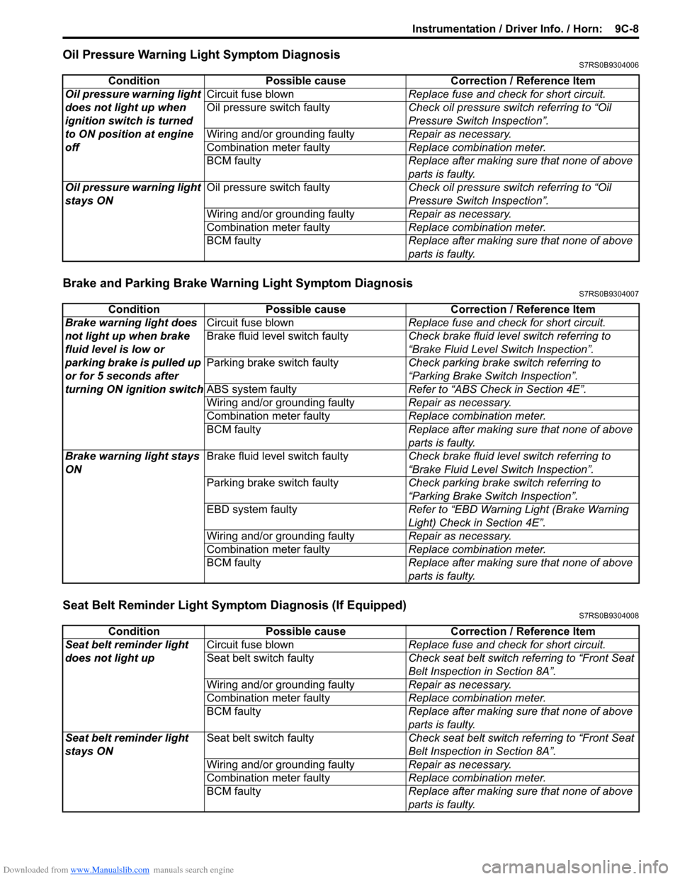
Oil Pressure Warning Light Symptom DiagnosisS7RS0B9304006
Brake and Parking Brake Warning Light Symptom DiagnosisS7RS0B9304007
Seat Belt Reminder Light Symptom Diagnosis (If Equipped)S7RS0B9304008
Condition Possible cause Correction / Reference Item
Oil pressure warning light
does not light up when
ignition switch is turned
to ON position at engine
off Circuit fuse blown
Replace fuse and check for short circuit.
Oil pressure switch faulty Check oil pressure switch referring to “Oil
Pressure Switch Inspection”.
Wiring and/or grounding faulty Repair as necessary.
Combination meter faulty Replace combination meter.
BCM faulty Replace after making sure that none of above
parts is faulty.
Oil pressure warning light
stays ON Oil pressure switch faulty
Check oil pressure switch referring to “Oil
Pressure Switch Inspection”.
Wiring and/or grounding faulty Repair as necessary.
Combination meter faulty Replace combination meter.
BCM faulty Replace after making sure that none of above
parts is faulty.
ConditionPossible cause Correction / Reference Item
Brake warning light does
not light up when brake
fluid level is low or
parking brake is pulled up
or for 5 seconds after
turning ON ignition switch Circuit fuse blown
Replace fuse and check for short circuit.
Brake fluid level switch faulty Check brake fluid level switch referring to
“Brake Fluid Level Switch Inspection”.
Parking brake switch faulty Check parking brake switch referring to
“Parking Brake Switch Inspection”.
ABS system faulty Refer to “ABS Check in Section 4E”.
Wiring and/or grounding faulty Repair as necessary.
Combination meter faulty Replace combination meter.
BCM faulty Replace after making sure that none of above
parts is faulty.
Brake warning light stays
ON Brake fluid level switch faulty
Check brake fluid level switch referring to
“Brake Fluid Level Switch Inspection”.
Parking brake switch faulty Check parking brake switch referring to
“Parking Brake Switch Inspection”.
EBD system faulty Refer to “EBD Warning Light (Brake Warning
Light) Check in Section 4E”.
Wiring and/or grounding faulty Repair as necessary.
Combination meter faulty Replace combination meter.
BCM faulty Replace after making sure that none of above
parts is faulty.
ConditionPossible cause Correction / Reference Item
Seat belt reminder light
does not light up Circuit fuse blown
Replace fuse and check for short circuit.
Seat belt switch faulty Check seat belt switch referring to “Front Seat
Belt Inspection in Section 8A”.
Wiring and/or grounding faulty Repair as necessary.
Combination meter faulty Replace combination meter.
BCM faulty Replace after making sure that none of above
parts is faulty.
Seat belt reminder light
stays ON Seat belt switch faulty
Check seat belt switch referring to “Front Seat
Belt Inspection in Section 8A”.
Wiring and/or grounding faulty Repair as necessary.
Combination meter faulty Replace combination meter.
BCM faulty Replace after making sure that none of above
parts is faulty.