Page 886 of 1496

Downloaded from www.Manualslib.com manuals search engine 6C-4 Power Assisted Steering System:
Schematic and Routing Diagram
EPS System Wiring Circuit DiagramS7RS0B6302001
M
5V
BRNRED/
BLU
BLK
RED
WHT
BLU
GRN
BRN YEL
E52-11
E52-14E52-12
E23-4
E23-26
E23-25 E51-1
E51-2
E52-18
E53-5
E53-7
E52-6
E52-8
E53-2
E52-9
E52-16
E52-19
GRY
PPL/WHT
[A ]
[E ]
12 3
4 5 67
89
11
10
12 13
141516
17 18 19 20
1
2
[B ][C ]
1210 9 8 7654 3 21
16 15 14 13 12 11
26 25 24 2322 21 20 19 18 17
32 31 30 29 28 27
[D]
5V
PPL
E52-4
11
12
13 14
15
10
9
16
12V
5V
5V
12V
REDE52-20E53-6
E53-4
E53-1
7654321
5
REDRED/
BLKWHT
6WHTWHT/BLKWHTBLK
12V
12V
17BLK
GRY
LT GRN
/BLK
E52-1
E52-5
E49-1
GRNGRNWHTBLK
WHY
G28-25G28-31
RED/BLK
18
3
4
4
7 8
4
4
1 2
4
E49-2BLK
I7RS0B630002-01
[A]: Connector “E52” (viewed from harness side) 4. Fuse 12. P/S motor
[B]: Connector “E49” (viewed from harness side ) 5. Left-front wheel speed sensor 13. Shield
[C]: Connector “E51” (viewed from harness side) 6 . Right-front wheel speed sensor 14. Torque sensor
[D]: Connector “G28” (viewed from harness side) 7. Combination meter 15. Torque sensor amplifier
[E]: Connector “E53” (viewed from harness side) 8. “EPS” warning light16. To ECM, BCM, Air bag SDM and ABS control module assembly
1. Main fuse box 9. Date link connector (DLC) 17. ABS/ESP ® control module
2. Ignition switch 10. ECM18. Individual circuit fuse box No.1
3. Junction block assembly 11. P/S control module
Page 908 of 1496
Downloaded from www.Manualslib.com manuals search engine 6C-26 Power Assisted Steering System:
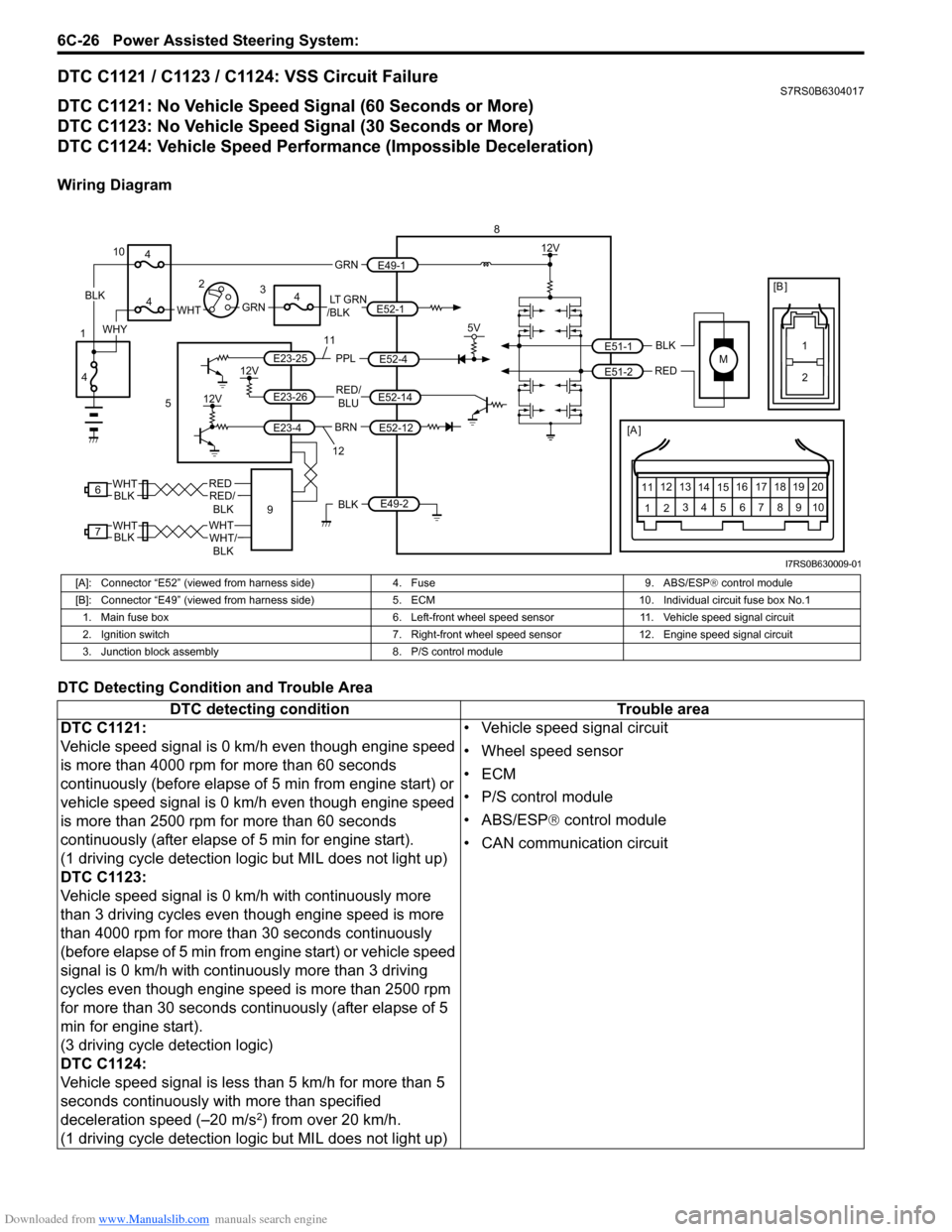
DTC C1121 / C1123 / C1124: VSS Circuit FailureS7RS0B6304017
DTC C1121: No Vehicle Speed Signal (60 Seconds or More)
DTC C1123: No Vehicle Speed Signal (30 Seconds or More)
DTC C1124: Vehicle Speed Performance (Impossible Deceleration)
Wiring Diagram
DTC Detecting Condition and Trouble Area
M
BRNRED/
BLU
BLK
RED
E52-14
E52-12
E23-4
E23-26
E23-25 E51-1
E51-2
[A ]
12
3
4 5 67
89
11
10
12 13
141516
17 18 19 20
5V
PPL
E52-4
8
5
12V
E49-2BLK
12V
12V
6REDRED/ BLKWHT
7WHTWHT/BLKWHTBLK BLK
111
2
[B ]
9
LT GRN
/BLKE52-1 E49-1
GRNGRNWHTBLK
WHY
10
3
4
4
4
4
1 2
12
I7RS0B630009-01
[A]: Connector “E52” (viewed from harness side)
4. Fuse9. ABS/ESP® control module
[B]: Connector “E49” (viewed from harness si de)5. ECM 10. Individual circuit fuse box No.1
1. Main fuse box 6. Left-front wheel speed sensor11. Vehicle speed signal circuit
2. Ignition switch 7. Right-front wheel speed sensor 12. Engine speed signal circuit
3. Junction block assembly 8. P/S control module
DTC detecting condition Trouble area
DTC C1121:
Vehicle speed signal is 0 km/h even though engine speed
is more than 4000 rpm for more than 60 seconds
continuously (before elapse of 5 min from engine start) or
vehicle speed signal is 0 km/h even though engine speed
is more than 2500 rpm for more than 60 seconds
continuously (after elapse of 5 min for engine start).
(1 driving cycle detection logic but MIL does not light up)
DTC C1123:
Vehicle speed signal is 0 km/h with continuously more
than 3 driving cycles even though engine speed is more
than 4000 rpm for more than 30 seconds continuously
(before elapse of 5 min from engine start) or vehicle speed
signal is 0 km/h with continuously more than 3 driving
cycles even though engine speed is more than 2500 rpm
for more than 30 seconds continuously (after elapse of 5
min for engine start).
(3 driving cycle detection logic)
DTC C1124:
Vehicle speed signal is less than 5 km/h for more than 5
seconds continuously with more than specified
deceleration speed (–20 m/s
2) from over 20 km/h.
(1 driving cycle detection logic but MIL does not light up) • Vehicle speed signal circuit
• Wheel speed sensor
•ECM
• P/S control module
• ABS/ESP®
control module
• CAN communication circuit
Page 986 of 1496
Downloaded from www.Manualslib.com manuals search engine 7B-38 Air Conditioning System: Automatic Type
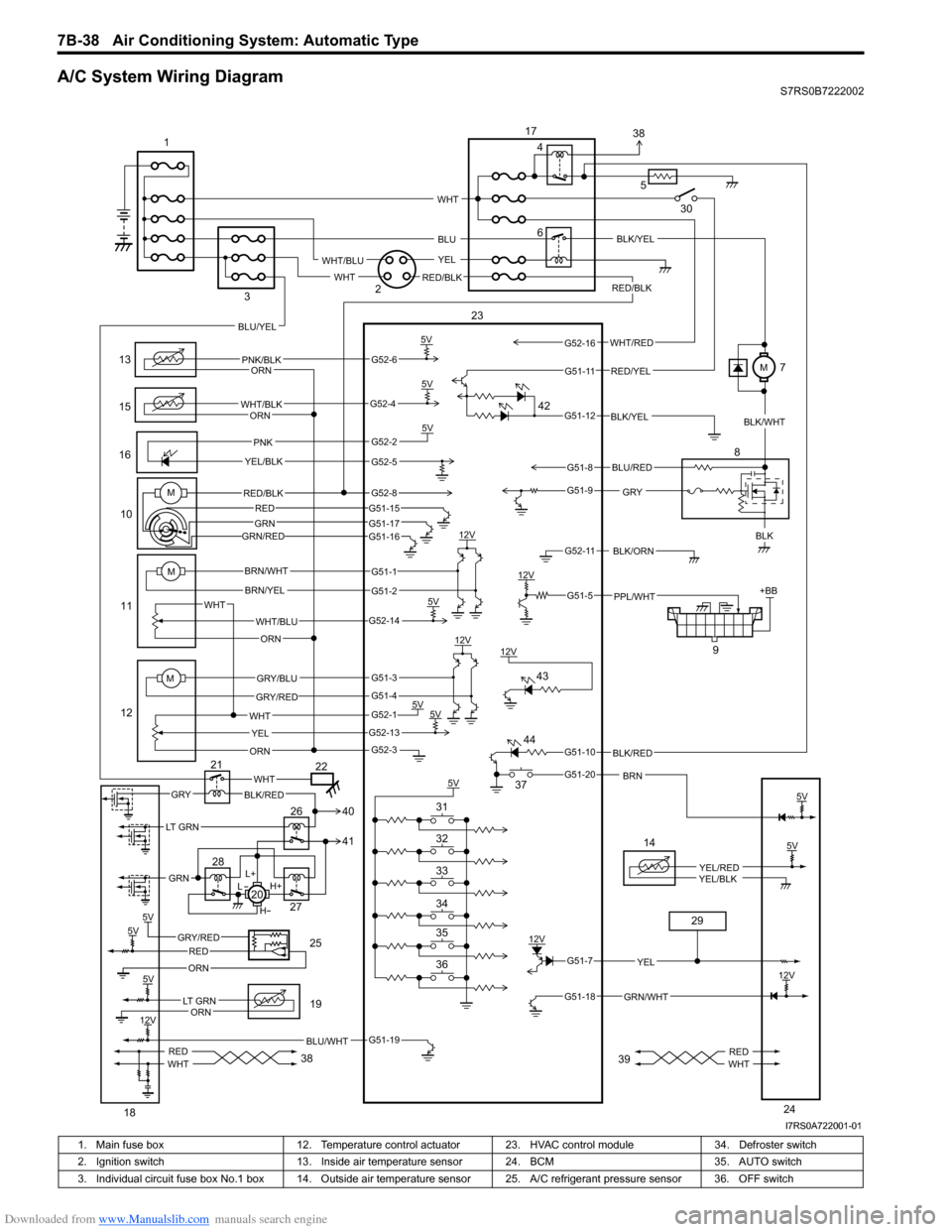
A/C System Wiring DiagramS7RS0B7222002
6
13
15
1610
11
12 9
12V
5V
5V5V
12V
12V
5V 5V
5V +BB
PNK/BLK
WHT/BLK
GRYBLK
WHT/BLU
WHT YEL
ORN
BRN/WHT
BRN/YEL
GRY/BLU
GRY/RED
PNK
YEL/BLK
BLK/ORN
PPL/WHT
12V BLK/YEL
WHT
ORN
ORN
ORN
5V
BLK/RED
BRN
RED/BLK
5V
5VGRY/REDRED
ORN
BLU/WHT
14
YEL/REDYEL/BLK
GRN/WHT
12V
YEL
L+
H+
L
H
WHTGRYBLK/RED
REDWHTREDWHT
M
M
WHT/RED
5
BLU
YEL
WHT
WHT/BLU
RED/BLKWHT
RED/YEL
BLU/YEL
LT GRN
GRN
BLU/RED
G52-6
G52-4
G52-2
G52-5
G51-1
G51-2
G52-14
G51-3
G51-4
G52-1
G52-13
G52-3
G51-19
G51-7
G51-18
G51-10
G51-20
G51-5
G52-11
G51-9
G51-8
G51-12
G51-11
G52-16
5V
12V
5V
12V
LT GRNORN
5V
23
1
2
3 4
8
17
18 19
20
21
22
24
25
26
27
28
29
30
36 35 34 33 32 31 37
38 3938
41 40
42
43
44
MRED/BLK
GRN/RED
G52-8G51-15
G51-17G51-16
REDGRN
BLK/YEL
BLK/WHT
M7
I7RS0A722001-01
1. Main fuse box 12. Temperature control actuator 23. HVAC control module 34. Defroster switch
2. Ignition switch 13. Inside air temperature sensor 24. BCM 35. AUTO switch
3. Individual circuit fuse box No.1 box 14. Outside air temper ature sensor 25. A/C refrigerant pressure sensor 36. OFF switch
Page 1177 of 1496
Downloaded from www.Manualslib.com manuals search engine Wiring Systems: 9A-6
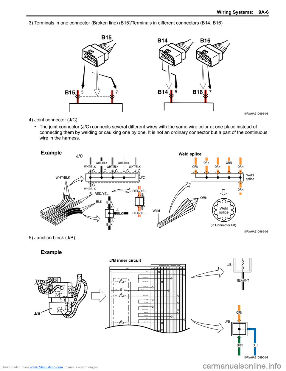
3) Terminals in one connector (Broken line) (B15)/Terminals in different connectors (B14, B16)
4) Joint connector (J/C)• The joint connector (J/C) connects several different wires with the same wire color at one place instead of
connecting them by welding or caulking one by one. It is not an ordinary connector but a part of the continuous
wire in the harness.
5) Junction block (J/B)
B15 B15
B14 B1657B14 B1657
I5RW0A910995-03
BLKBLK
A
A
A B
B
RED/YEL
WeldORN
WHT/BLK
J/C
Weld splice
BLKBLK
RED/YEL
RED/YEL
WHT/BLK
WHT/BLK
WHT/BLKWHT/BLKWHT/BLKWHT/BLKC
CCCCCWeld
splice
(in Connector list)
J/C
ORNORNORNORNORN
ORN
Weld
splice
Example
I5RW0A910989-02
IMMOBI IG IG1IG Coil, etc E39 E41E40
BCM G34
G33
G32 K01 L04 L05 L06
IG Coil
IG1
15A
MTR10A
A/B15A
2
65
13
J/B Connector No. / Terminal No.
BCM ;IG1
MTR Power, etc
A/B CONTK-LINE K-LINE
A/B SIGNAL
A/B SIGNAL
A/B SIG
A/B SIG
IG Sig 10AEPS ATMTA
4
6
1
3
24
8
11
9
12
9
11
23
25
30
29
Example
J/B
J/B
ORN
GRNBLU
J/B
J/B inner circuit
BLK/WHT
I5RW0A910990-03
Page 1179 of 1496
Downloaded from www.Manualslib.com manuals search engine Wiring Systems: 9A-8
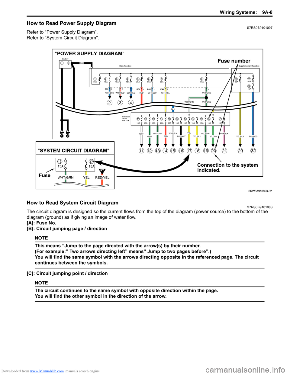
How to Read Power Supply DiagramS7RS0B9101007
Refer to “Power Supply Diagram”.
Refer to “System Circuit Diagram”.
How to Read System Circuit DiagramS7RS0B9101008
The circuit diagram is designed so the current flows from the top of the diagram (power source) to the bottom of the
diagram (ground) as if giving an image of water flow.
[A]: Fuse No.
[B]: Circuit jumping page / direction
NOTE
This means “Jump to the page directed with the arrow(s) by their number.
(For example:” Two arrows directing left” means” Jump to two pages before”.)
You will find the same symbol with the arrows directing opposite in the referenced page. The circuit
continues between the symbols.
[C]: Circuit jumping point / direction
NOTE
The circuit continues to the same symbol with opposite direction within the page.
You will find the other symbol in the direction of the arrow.
Connection to the system
indicated.
"POWER SUPPLY DIAGRAM"
-+
1
Battery
80A
215A315A415A525A67850A 30A2930A3215A
960A
60A
BLK
YEL/BLKPNK/BLKLT GRNYEL/GRNYEL/BLUBLK/WHTWHT/BLKWHT/GRNREDGRNWHT
WHT/BLUWHT/REDWHT/BLUWHT/YELWHT/GRN
WHT/GRNWHT/GRN
BLU
BLU/REDRED
YELBLU/RED
Individual
circuit
fuse box
Main fuse box
Supplementary fuse box
11
11
243
121314151617181920212932
1213141516171819202115A 15A 15A 20A 20A 15A 15A 15A 15A 15A 15A
E44
321
B011E45 1 E4021
FuseRED/YEL
YEL
WHT/GRN
15A
15A
1317
"SYSTEM CIRCUIT DIAGRAM"
Fuse number
1
2
RY
I5RW0A910993-02
Page 1225 of 1496
Downloaded from www.Manualslib.com manuals search engine Wiring Systems: 9A-54
BLU
12
Diagnosis
connector #1
E572
ECM
GRN
Relay #2Relay #3
G
"A-4"
E2348
RHD
WHT
BCM
APP sensor
Electric throttle body
Throttle position sensor
SUB
open
close
open
close
open
close
open
close
MAIN
SUB
MAIN
Throttle
actuator
REDBRNGRNBLUREDYELWHTBLKWHTGRNREDLT GRN/REDLT GRN/BLK
E46
3 18
TCM
WHTRED
7 17
C37
C34
1 2
ABS
Cont.MESP
Cont.M
E0310 8
or
E612
3C421 256431564
12 13
RW
5041424054434445513634523735E23
C37
A/T
BLK
31
22
(CAN) (CAN)
M13A engine, M15A engine
M16A engine
AB
B
RB
B
A
I7RS0B910914-01
Page 1237 of 1496
Downloaded from www.Manualslib.com manuals search engine Wiring Systems: 9A-66
J24L37
J21
J192352 2133
5
L13
J1621 3
5
J23 J18
RED/BLKBLU/YELWHT/BLUGRN/YELWHT/BLUWHT/GRN
4
1211J01
L07
14
21
M
GRNRED
14
21
GRNRED
1
2
3
4
5
6
UNLOCK UP
OFF
DOWN
UP
OFF
DOWN
LOCK IG E RLU RLD
Rear (L)
Sub switch
M
UNLOCK UP
OFF
DOWN
UP
OFF
DOWN
LOCK IG E RRU RRD
WHT/BLU
WHT/BLUWHT/BLUWHT/BLU
GRN/YEL
BLU/YEL
WHT/GRN
RED/BLK
BLU/YELGRN/YELRED/BLKWHT/GRN
Rear (R)
Sub switch
J01
L07
I7RS0B910920-01
Page 1408 of 1496
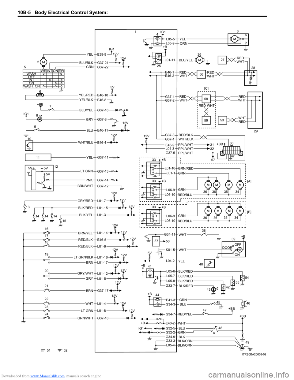
Downloaded from www.Manualslib.com manuals search engine 10B-5 Body Electrical Control System:
GRY/RED
BLK/YEL
BLK/RED
12V
12V
+BB
BLU/YEL
BLU
12V
WHT/BLU
12V
+BB
RED/YEL
G34-7
YEL/REDYEL/BLK
5V
IG1
IG1
IG1
WASH
OFFINT ON
WASH, ON WR EWON
INT
BLU/BLK
YELE39-9
GRN
12V12V
YELL05-5
BLU/YEL
PPL/WHT
12V
G37-5PPL/WHTPPL/WHT
+B +B
GRN/RED
GRN
GRN
RED/BLU
L06-9
L06-10
L01-10L01-1
ON
DOOR
OFF+B
+B
IG1 WHT
K01-5
12V
12V
12V
5V
12V
12V
L04-2YEL
RED/BLK
WHT
GRN/WHT
BRN
LT GRN/BLK
BRN
GRY/WHT
GRY
12VLT GRN
12V
12V
12V
12V
RED/BLK
LT GRN
BRN/WHT
5V5V
5V
PNK
+BB
GRNG32-2
+B
BLKBLK/ORNG34-9
G33-3
BLK/ORNL05-4
BLU
G32-5
WHTE40-2
G34-11
E41-3G34-3BLU
REDWHTREDWHT
+BB
1
2 3
4
5 67
8
9
10
11 12
13 14 14 14 15
16
17
18
19
20
21
22
23
24
52
51 25
26
28
30
31
32
33
33 36 36
+B
GRN
RED/BLU
L06-9
L06-10
33
36 3635 34
35 34
37 50 38
39
40
45 46
47
48 49
[B] [A]
[C]
G37-21
E46-10
GRY
YEL
BRN/YEL
L01-12
L01-4
L01-8
L01-11
GRN
WHT
G37-22
E46-4
G37-8
E46-8
G37-16
E46-11
G37-11
G37-13
G37-14
G37-12
L01-7
L01-15
L01-3
L01-14
L01-16
E46-5
L01-6
L01-17
L01-5
G37-17
G37-18
E46-1E46-2
E46-9
+B
12V
12V
BLK/RED
BLK/REDL05-6
G33-7 54
BLK/REDL05-7
55
BLK/REDL05-842
43
44
27REDWHT
57
+B41
56
ORNL05-9
L04-3
REDWHTREDWHT
REDWHT
REDWHT
G37-4G37-2
RED/BLKWHT/BLKG37-3G37-1 58
59
29
53
I7RS0BA20003-02