2007 SUZUKI SWIFT AT transaxle service
[x] Cancel search: AT transaxle servicePage 644 of 1496
Downloaded from www.Manualslib.com manuals search engine 5-1 Precautions:
Transmission / Transaxle
Precautions
Precautions
Precautions on Transmission / TransaxleS7RS0B5000001
Air Bag Warning
Refer to “Air Bag System Service Warning in Section 00”.
Precautions in Diagnosing Trouble
Refer to “Precautions in Diagnosing Trouble in Section 5A”.
Precautions for Disassembly and Reassembly
Refer to “Precautions for Disassembly and Reassembly in Section 5A”.
Precaution for CAN Communication System
Refer to “Precaution for CAN Communication System in Section 00”.
Precautions for Electrical Circuit Service
Refer to “Precautions for Electric al Circuit Service in Section 00”.
Page 645 of 1496
Downloaded from www.Manualslib.com manuals search engine Automatic Transmission/Transaxle: 5A-1
Transmission / Transaxle
Automatic Transmission/Transaxle
Precautions
Precautions in Diagnosing TroubleS7RS0B5100001
• Do not disconnect couplers from TCM, battery cable from battery, TCM ground wire harness from engine or
main fuse before checking the diagnostic information
(DTC, freeze frame data, etc.) stored in TCM memory.
Such disconnection will clea r memorized information
in TCM memory.
• Diagnostic information stored in TCM memory can be cleared as well as checked by using SUZUKI scan
tool or generic scan tool. Before using scan tool, read
its Operator’s (Instruction) Manual carefully to have
good understanding as to what functions are available
and how to use it.
It is indistinguishable wh ich module turns on MIL
because not only ECM but also TCM turns on MIL.
Therefore, check both ECM and TCM for DTC when
MIL lights on.
When checking TCM for DTC, keep in mind that DTC
is displayed on the scan tool as follows depending on
the scan tool used.
– SUZUKI scan tool displays DTC detected by TCM.
– Generic scan tool displays DTC detected by each of ECM and TCM simultaneously.
• Using SUZUKI scan tool the diagnostic information stored in TCM memory can be checked and cleared
as well. Before its use, be sure to read Operator’s
Manual supplied with it carefully to have good
understanding of its functions and usage.
• Be sure to read “Precautions for Electrical Circuit Service in Section 00” befo re inspection and observe
what is written there.
• TCM replacement
– When substituting a known-good TCM, check that all relays and actuators have resistance of
specified value.
Neglecting this check may result in damage to good
TCM.
• Communication of ECUs , ECM, TCM, ABS control
module, keyless start control module and BCM is
established by CAN (Controller Area Network).
Therefore, handle CAN communication line with care
referring to “Precaution for CAN Communication
System in Section 00”.
Precautions for Disassembly and ReassemblyS7RS0B5100002
When repairing automatic transaxle, it is necessary to
conduct the on-vehicle test to investigate where the
cause of the trouble lies first.
Then whether overhaul should be done or not is
determined. If the transaxle is disassembled without
such preliminary procedure, not only the cause of the
trouble would be unknown, but also a secondary trouble
may occur and often time would be wasted.
As the automatic transaxle consists of high precision
component, the following cautions should be strictly
observed when handling its parts in disassembly and
reassembly.
• Disassembling valve body assembly is prohibited
essentially. However, a few parts can be
disassembled. When disassembling valve body
component parts, confirm whether their parts are
allowed to disassemble or not referring to “Valve Body
Assembly Disassembly and Reassembly”.
• When component part of forward clutch, direct clutch, 2nd brake and/or O/D and 2nd coast brake, namely
clutch disc, brake disc, retaining plate and/or
separator plate, have been replaced, all learned
contents, which have been stored in TCM memory by
executing learning control, should be initialized
referring to “Learning Control Initialization”.
• Make sure to wash dirt off from the transaxle so that no such dirt will enter the transaxle during
dismounting and remounting.
• Select a clean place free from dust and dirt for overhauling.
• Place a rubber mat on the work bench to protect parts from damage.
• Work gloves or shop cloth should not be used. (Use a nylon cloth or a paper towel.)
• When separating the case joint, do not pry with a screwdriver or such but tap with a plastic hammer
lightly.
• Make sure to wash dirt off from the transaxle so that no such dirt will enter the transaxle during
disassembly and reassembly.
• Wash the disassembled parts in ATF (Automatic Transaxle Fluid) or kerosene (using care not to allow
ATF or kerosene to get on your face, etc.) and confirm
that each fluid passage is not clogged by blowing air
into it. But use kerosene to wash the discs, resin
washers and rubber parts.
• Replace each gasket, oil seal and O-ring with a new one.
• Apply ATF to sliding or rotating parts before
reassembly.
Page 812 of 1496
Downloaded from www.Manualslib.com manuals search engine 5A-168 Automatic Transmission/Transaxle:
Special Tools and Equipment
Recommended Service MaterialS7RS0B5108001
NOTE
Required service material is also described in the following.
“Select Cable Components”
“Automatic Transaxle Unit Components”
“Automatic Transaxle Assembly Components”
“Oil Pump Assembly Components”
“Direct Clutch Assembly Components”
“Forward and Reverse Clutch Assembly Components”
“2nd Brake Piston Assembly Components”
“Transaxle Rear Cover (O/D and 2nd Coast Brake Piston) Assembly Components”
“Countershaft Assembly Components”
“Valve Body Assembly Components”
“Differential Assembly Components”
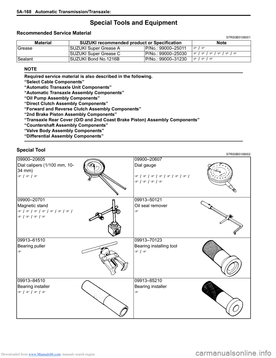
Special ToolS7RS0B5108002
Material SUZUKI recommended product or Specification Note
Grease SUZUKI Super Grease A P/No.: 99000–25011�) / �)
SUZUKI Super Grease C P/No.: 99000–25030�) / �) / �) / �) / �) / �)
Sealant SUZUKI Bond No.1216B P/No.: 99000–31230�) / �) / �)
09900–20605 09900–20607
Dial calipers (1/100 mm, 10-
34 mm) Dial gauge
�) / �) / �)�) / �) / �) / �) / �) / �) / �) /
�) / �) / �) / �)
09900–20701 09913–50121
Magnetic stand Oil seal remover
�) / �) / �) / �) / �) / �) / �) /
�) / �) / �) / �) �)
09913–61510 09913–70123
Bearing puller Bearing installing tool
�)�) / �)
09913–84510 09913–85210
Bearing installer Bearing installer
�) / �) / �) / �)�)
Page 817 of 1496

Downloaded from www.Manualslib.com manuals search engine Manual Transmission/Transaxle: 5B-3
Diagnostic Information and Procedures
Manual Transaxle Symptom DiagnosisS7RS0B5204001
Repair Instructions
Manual Transaxle Oil ChangeS7RS0B5206001
1) Before changing or inspecting oil, be sure to stop engine and lift vehicle horizontally.
2) With vehicle lifted up, check oil level and leakage. If leakage exists, correct it.
NOTE
Whenever vehicle is hoisted for any other
service work than oil change, also be sure to
check for oil leakage.
3) Remove oil filler plug (2).
4) Remove drain plug (1), and drain old oil. 5) Apply sealant to thread of drain plug (1), and tighten
it to specified torque.
“A”: Sealant 99000–31260 (SUZUKI Bond
No.1217G)
Tightening torque
Transaxle oil drain plug (a): 21 N·m (2.1 kgf-m,
15.5 lb-ft)
6) Pour new specified oil unt il oil level reaches bottom
of oil filler plug hole (3) as shown in figure.NOTE
It is highly recommended to use API GL-4
75W-90 gear oil.
Transaxle oil specification
: API GL-4 (For SAE classification, refer to
viscosity chart [A] in figure.)
Manual transaxle oil capacity
Reference: 2.0 liters (4.2/3.5 US/Imp. pt)
Condition Possible cause Correction / Reference Item
Gears slipping out of
mesh Worn shift fork shaft
Replace.
Worn shift fork or synchronizer sleeve Replace.
Weak or damaged locating springs Replace.
Worn bearings on input shaft or
countershaft Replace.
Worn chamfered tooth on sleeve and
gear Replace sleeve and gear.
Hard shifting Maladjusted gear select control cable Adjust.
Inadequate or insufficient lubricant Replenish.
Improper clutch pedal free travel Replace clutch master cylinder or clutch pedal
arm.
Distorted or broken clutch disc Replace.
Damaged clutch pressure plate Replace clutch cover.
Worn synchronizer ring Replace.
Worn chamfered tooth on sleeve or gear Replace sleeve or gear.
Worn gear shift / select control cables
joint Replace.
Distorted shift shaft Replace.
Worn gear shift / select control cables Replace.
Noise Inadequate or insufficient lubricant Replenish.
Damaged or worn bearing(s) Replace.
Damaged or worn gear(s) Replace.
Damaged or worn synchronizer parts Replace.
Page 835 of 1496
Downloaded from www.Manualslib.com manuals search engine Manual Transmission/Transaxle: 5B-21
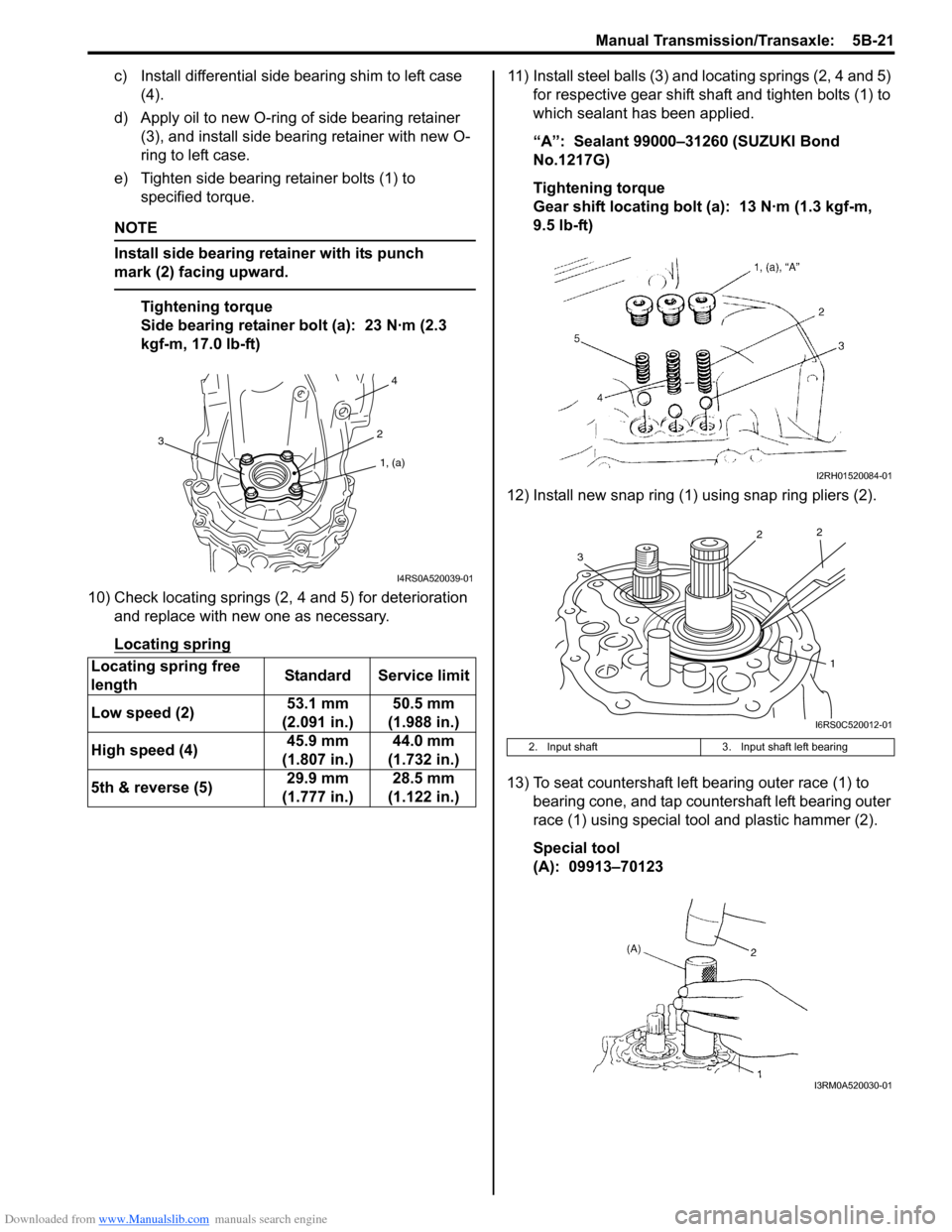
c) Install differential side bearing shim to left case (4).
d) Apply oil to new O-ring of side bearing retainer (3), and install side bea ring retainer with new O-
ring to left case.
e) Tighten side bearing retainer bolts (1) to specified torque.
NOTE
Install side bearing retainer with its punch
mark (2) facing upward.
Tightening torque
Side bearing retainer bolt (a): 23 N·m (2.3
kgf-m, 17.0 lb-ft)
10) Check locating springs (2, 4 and 5) for deterioration and replace with new one as necessary.
Locating spring
11) Install steel balls (3) and locating springs (2, 4 and 5) for respective gear shift shaft and tighten bolts (1) to
which sealant has been applied.
“A”: Sealant 99000–31260 (SUZUKI Bond
No.1217G)
Tightening torque
Gear shift locating bolt (a): 13 N·m (1.3 kgf-m,
9.5 lb-ft)
12) Install new snap ring (1) using snap ring pliers (2).
13) To seat countershaft left bearing outer race (1) to bearing cone, and tap countershaft left bearing outer
race (1) using special tool and plastic hammer (2).
Special tool
(A): 09913–70123
Locating spring free
length
Standard Service limit
Low speed (2) 53.1 mm
(2.091 in.) 50.5 mm
(1.988 in.)
High speed (4) 45.9 mm
(1.807 in.) 44.0 mm
(1.732 in.)
5th & reverse (5) 29.9 mm
(1.777 in.) 28.5 mm
(1.122 in.)
1, (a)
2
4
3
I4RS0A520039-01
2. Input shaft 3. Input shaft left bearing
I2RH01520084-01
1
2
2
3
I6RS0C520012-01
I3RM0A520030-01
Page 845 of 1496
Downloaded from www.Manualslib.com manuals search engine Manual Transmission/Transaxle: 5B-31
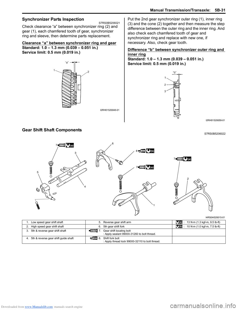
Synchronizer Parts InspectionS7RS0B5206021
Check clearance “a” between synchronizer ring (2) and
gear (1), each chamfered tooth of gear, synchronizer
ring and sleeve, then determine parts replacement.
Clearance “a” between synchronizer ring and gear
Standard: 1.0 – 1.3 mm (0.039 – 0.051 in.)
Service limit: 0.5 mm (0.019 in.)Put the 2nd gear synchronizer outer ring (1), inner ring
(3) and the cone (2) together and then measure the step
difference between the outer ring and the inner ring. And
also check each chamfered tooth of gear and
synchronizer ring and replace with new one, if
necessary. Also, check gear tooth.
Difference “b” between synchronizer outer ring and
inner ring
Standard: 1.0 – 1.3 mm (0.039 – 0.051 in.)
Service limit: 0.5 mm (0.019 in.)
Gear Shift Shaft ComponentsS7RS0B5206022
I2RH01520048-01
I2RH01520059-01
5
3
4 6
1
2
8
7
77
(a)
(b)
(a)
(a)
I4RS0A520015-01
1. Low speed gear shift shaft
5. Reverse gear shift arm : 13 N⋅m (1.3 kgf-m, 9.5 lb-ft)
2. High speed gear shift shaft 6. 5th gear shift fork : 10 N⋅m (1.0 kgf-m, 7.5 lb-ft)
3. 5th & reverse gear shift shaft 7. Gear shift locating bolt
: Apply sealant 99000-31260 to bolt thread.
4. 5th & reverse gear shift guide shaft 8. Shift fork bolt
: Apply thread lock 99000-32110 to bolt thread.
Page 846 of 1496
Downloaded from www.Manualslib.com manuals search engine 5B-32 Manual Transmission/Transaxle:
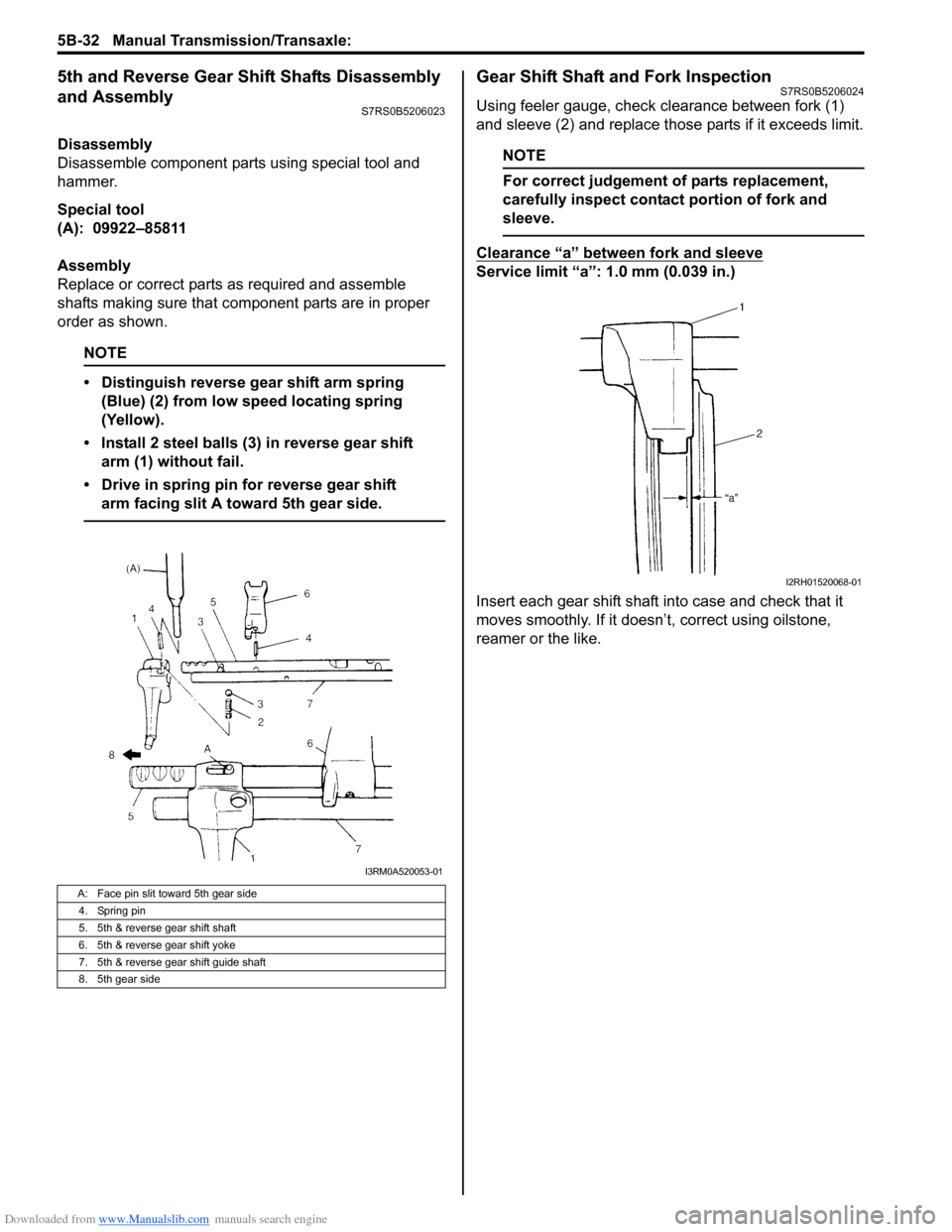
5th and Reverse Gear Shift Shafts Disassembly
and Assembly
S7RS0B5206023
Disassembly
Disassemble component parts using special tool and
hammer.
Special tool
(A): 09922–85811
Assembly
Replace or correct parts as required and assemble
shafts making sure that component parts are in proper
order as shown.
NOTE
• Distinguish reverse gear shift arm spring (Blue) (2) from low speed locating spring
(Yellow).
• Install 2 steel balls (3) in reverse gear shift arm (1) without fail.
• Drive in spring pin for reverse gear shift arm facing slit A toward 5th gear side.
Gear Shift Shaft and Fork InspectionS7RS0B5206024
Using feeler gauge, check clearance between fork (1)
and sleeve (2) and replace those parts if it exceeds limit.
NOTE
For correct judgement of parts replacement,
carefully inspect contact portion of fork and
sleeve.
Clearance “a” between fork and sleeve
Service limit “a”: 1.0 mm (0.039 in.)
Insert each gear shift shaft into case and check that it
moves smoothly. If it doesn’t, correct using oilstone,
reamer or the like.
A: Face pin slit toward 5th gear side
4. Spring pin
5. 5th & reverse gear shift shaft
6. 5th & reverse gear shift yoke
7. 5th & reverse gear shift guide shaft
8. 5th gear side
I3RM0A520053-01
I2RH01520068-01
Page 850 of 1496
Downloaded from www.Manualslib.com manuals search engine 5B-36 Manual Transmission/Transaxle:
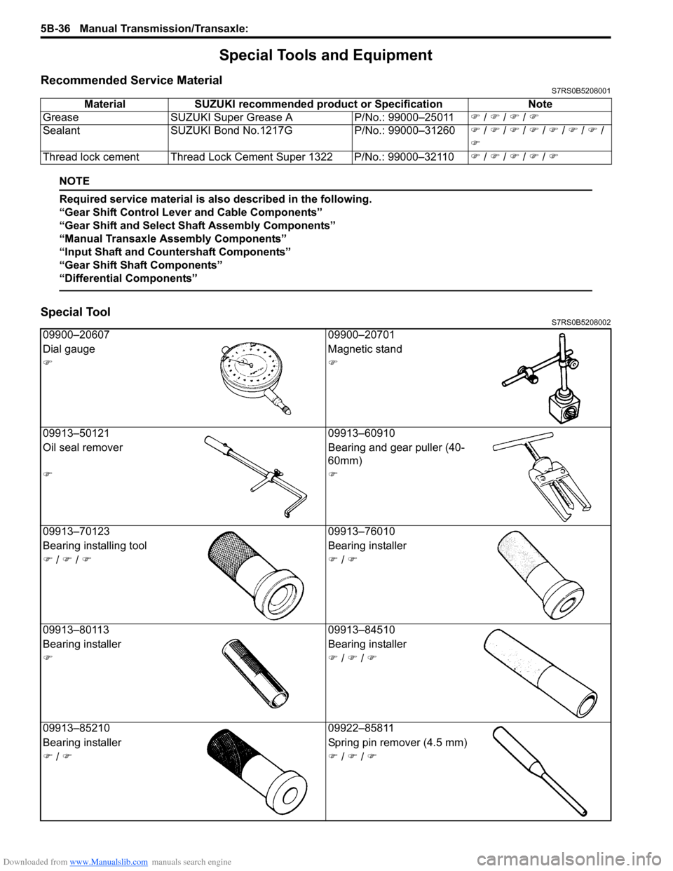
Special Tools and Equipment
Recommended Service MaterialS7RS0B5208001
NOTE
Required service material is also described in the following.
“Gear Shift Control Leve r and Cable Components”
“Gear Shift and Select Shaft Assembly Components”
“Manual Transaxle Assembly Components”
“Input Shaft and Countershaft Components”
“Gear Shift Shaft Components”
“Differential Components”
Special ToolS7RS0B5208002
Material SUZUKI recommended product or Specification Note
Grease SUZUKI Super Grease A P/No.: 99000–25011�) / �) / �) / �)
Sealant SUZUKI Bond No.1217G P/No.: 99000–31260�) / �) / �) / �) / �) / �) / �) /
�)
Thread lock cement Thread Lock Cement Super 1322 P/No.: 99000–32110 �) / �) / �) / �) / �)
09900–20607 09900–20701
Dial gauge Magnetic stand
�)�)
09913–50121 09913–60910
Oil seal remover Bearing and gear puller (40-
60mm)
�)�)
09913–70123 09913–76010
Bearing installing t ool Bearing installer
�) / �) / �)�) / �)
09913–80113 09913–84510
Bearing installer Bearing installer
�)�) / �) / �)
09913–85210 09922–85811
Bearing installer Spring pin remover (4.5 mm)
�) / �)�) / �) / �)