2007 SUZUKI SWIFT 1a 124
[x] Cancel search: 1a 124Page 598 of 1496

Downloaded from www.Manualslib.com manuals search engine 4F-24 Electronic Stability Program:
Circuit Description
Operation (ON/OFF) of ABS warning lamp is controlled by ESP® control module through lamp driver module in
combination meter.
If antilock brake system is in good condition, ESP ® control module turns ABS warning lamp ON at the ignition switch
ON, keeps it ON for 2 seconds and then turns it OFF. If an abnormality in the system is detected, ABS warning lamp is
turned ON continuously by ESP ® control module. Also, it is turned ON continuously by lamp driver module when the
connector of ESP ® control module is disconnected.
Troubleshooting
Refer to “Troubleshooting” under “ESP ® Warning Lamp Does Not Come ON at Ignition Switch ON”.
ABS Warning Lamp Comes ON SteadyS7RS0B4604049
Wiring Diagram
Refer to “Wiring Diagram” under “ABS Warning Lamp Does Not Come ON at Ignition Switch ON”.
Circuit Description
Refer to “Circuit Description” u nder “ABS Warning Lamp Does Not Co me ON at Ignition Switch ON”.
Troubleshooting
Refer to “Troubleshooting” under “ESP ® Warning Lamp Comes ON Steady”.
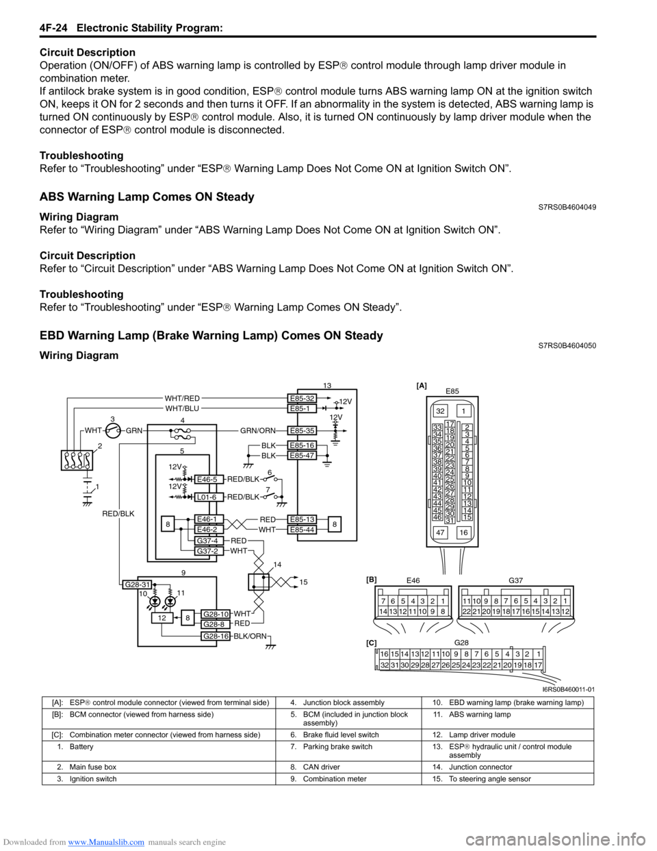
EBD Warning Lamp (Brake Warning Lamp) Comes ON SteadyS7RS0B4604050
Wiring Diagram
[A]
E85
161
15
2
3
4
5
6
7
8
9
10
11
12
13
14
17
18
19
20
21
22
23
24
25
26
27
28
29
30
31
3233
34
35
36
37
38
39
40
41
42
43
44
45
46
47WHTGRN
3
E85-13
E85-44REDWHT8 5E46-1E46-2
4
13
8
E85-16
E85-47BLKBLK
1110
12
BLK/ORN
REDWHT
REDWHT
G37-4G37-2
G28-10G28-8
G28-16
12V
12VE85-32E85-1
E85-35
WHT/REDWHT/BLU
GRN/ORN
8
2
1
9 1415
[B]
G37
E46
124
53
67
891011121314124
53
67
891011
1213141516171819202122
[C] G28
12345678910111213141516
17181920212223242526272829303132
12V
12V
6
7E46-5
L01-6
RED/BLK
RED/BLK
G28-31
RED/BLK
I6RS0B460011-01
[A]: ESP ® control module connector (viewed from terminal side) 4. Junction block assembly 10. EBD warning lamp (brake warning lamp)
[B]: BCM connector (viewed from harness side) 5. BCM (included in junction block
assembly) 11. ABS warning lamp
[C]: Combination meter connector (viewed from harness side) 6. Brake fluid level switch 12. Lamp driver module 1. Battery 7. Parking brake switch 13. ESP ® hydraulic unit / control module
assembly
2. Main fuse box 8. CAN driver 14. Junction connector
3. Ignition switch 9. Combination meter 15. To steering angle sensor
Page 600 of 1496
![SUZUKI SWIFT 2007 2.G Service Workshop Manual Downloaded from www.Manualslib.com manuals search engine 4F-26 Electronic Stability Program:
Serial Data Link Circuit CheckS7RS0B4604012
Wiring Diagram
Inspection
[A]E85
161
15
2
3
4
5
6
7
8
9
10
11
SUZUKI SWIFT 2007 2.G Service Workshop Manual Downloaded from www.Manualslib.com manuals search engine 4F-26 Electronic Stability Program:
Serial Data Link Circuit CheckS7RS0B4604012
Wiring Diagram
Inspection
[A]E85
161
15
2
3
4
5
6
7
8
9
10
11](/manual-img/20/7607/w960_7607-599.png)
Downloaded from www.Manualslib.com manuals search engine 4F-26 Electronic Stability Program:
Serial Data Link Circuit CheckS7RS0B4604012
Wiring Diagram
Inspection
[A]E85
161
15
2
3
4
5
6
7
8
9
10
11
12
13
14
17
18
19
20
21
22
23
24
25
26
27
28
29
30
31
3233
34
35
36
37
38
39
40
41
42
43
44
45
46
47WHTGRN
3
E85-13REDWHT6 5E46-1E46-2
4
10
6
E85-16
E85-47BLKBLK
8
9
BLK/ORN
REDWHT
REDWHT
G37-4G37-2
G28-10G28-8
G28-16
G28-31
12V
12VE85-32E85-1
E85-35
WHT/REDWHT/BLU
GRN/ORN
6
2
1
7 1415 [B]
G37
E46
124
53
67
891011121314124
53
67
891011
1213141516171819202122
[C] G28
12345678910111213141516
17181920212223242526272829303132
12V
11
PPL/WHT
PPL/WHT
E85-33
E85-44
12
13
WHTWHT/REDB
G G1
RED/BLK
I6RS0B460012-01
[A]: ESP
® control module connector (viewed
from terminal side) 4. Junction block assembly 10. ESP
® hydraulic unit / control module assembly
[B]: BCM connector (viewed from harness side) 5. BCM (included in junction block
assembly) 11. Data link connector (DLC)
[C]: Combination meter connector (viewed from harness side) 6. CAN driver 12. To SDM
1. Battery 7. Combination meter 13. To ECM and P/S control module
2. Main fuse box 8. ESP ® warning lamp 14. Junction connector
3. Ignition switch 9. Lamp driver module 15. To steering angle sensor
Step Action YesNo
1 Check ESP ® warning lamp
1) Turn ignition switch to ON position.
Does ESP
® warning lamp come ON? Go to Step 2. Go to Step 6.
2 Check fuse
1) Turn ignition switch to OFF position.
Are main fuses for good condition? Go to Step 3. Replace fuse and check
for short.
3 Check ESP ® control module power supply circuit
1) Disconnect ESP ® control module connector.
2) Check for proper connection to ESP ® control module
connector at terminal “E85-35”.
3) If OK, then turn ignition switch to ON position and measure voltage between terminal “E85-35” and vehicle
body ground.
Is it 10 – 14 V? Go to Step 4.
“GRN/ORN” wire circuit
open.
Page 604 of 1496

Downloaded from www.Manualslib.com manuals search engine 4F-30 Electronic Stability Program:
DTC Troubleshooting
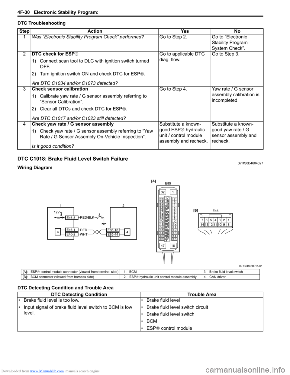
DTC C1018: Brake Fluid Level Switch FailureS7RS0B4604027
Wiring Diagram
DTC Detecting Condition and Trouble AreaStep Action Yes No
1 Was “Electronic Stability Pr ogram Check” performed? Go to Step 2. Go to “Electronic
Stability Program
System Check”.
2 DTC check for ESP®
1) Connect scan tool to DLC with ignition switch turned
OFF.
2) Turn ignition switch ON and check DTC for ESP ®.
Are DTC C1034 and/or C1073 detected? Go to applicable DTC
diag. flow.
Go to Step 3.
3 Check sensor calibration
1) Calibrate yaw rate / G sensor assembly referring to
“Sensor Calibration”.
2) Clear all DTCs and check DTC for ESP ®.
Are DTC C1017 and/or C1023 still detected? Go to Step 4. Yaw rate / G sensor
assembly calibration is
incompleted.
4 Check yaw rate / G sensor assembly
1) Check yaw rate / G sensor assembly referring to “Yaw
Rate / G Sensor Assembly On-Vehicle Inspection”.
Is it good condition? Substitute a known-
good ESP
® hydraulic
unit / control module
assembly and recheck. Substitute a known-
good yaw rate / G
sensor assembly and
recheck.
[A]
E85
161
15
2
3
4
5
6
7
8
9
10
11
12
13
14
17
18
19
20
21
22
23
24
25
26
27
28
29
30
31
3233
34
35
36
37
38
39
40
41
42
43
44
45
46
47 [B]
E46
124
53
67
891011121314
E85-13
E85-44REDWHT4E46-1E46-2
124
12V3E46-5RED/BLK
I6RS0B460015-01
[A]: ESP
® control module connector (viewed from terminal side) 1. BCM 3. Brake fluid level switch
[B]: BCM connector (viewed from harness side) 2. ESP ® hydraulic unit control module assembly 4. CAN driver
DTC Detecting Condition Trouble Area
• Brake fluid level is too low.
• Input signal of brake fluid level switch to BCM is low level. • Brake fluid level
• Brake fluid level switch circuit
• Brake fluid level switch
•BCM
• ESP
® control module
Page 611 of 1496

Downloaded from www.Manualslib.com manuals search engine Electronic Stability Program: 4F-37
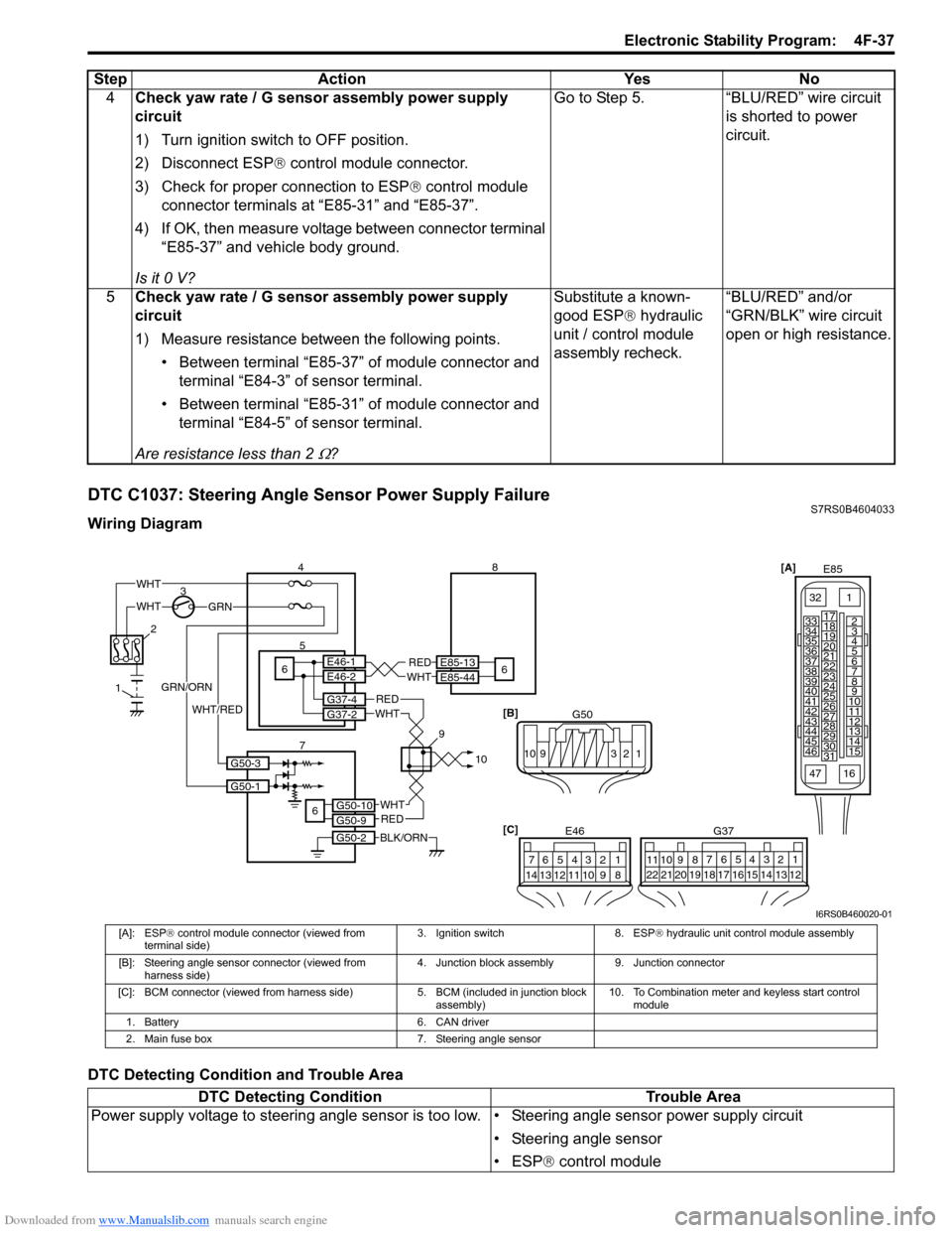
DTC C1037: Steering Angle Sensor Power Supply FailureS7RS0B4604033
Wiring Diagram
DTC Detecting Condition and Trouble Area4
Check yaw rate / G sensor assembly power supply
circuit
1) Turn ignition switch to OFF position.
2) Disconnect ESP ® control module connector.
3) Check for proper connection to ESP ® control module
connector terminals at “E85-31” and “E85-37”.
4) If OK, then measure voltage between connector terminal “E85-37” and vehicle body ground.
Is it 0 V? Go to Step 5. “BLU/RED” wire circuit
is shorted to power
circuit.
5 Check yaw rate / G sensor assembly power supply
circuit
1) Measure resistance between the following points.
• Between terminal “E85-37” of module connector and terminal “E84-3” of sensor terminal.
• Between terminal “E85-31” of module connector and terminal “E84-5” of sensor terminal.
Are resistance less than 2
Ω? Substitute a known-
good ESP
® hydraulic
unit / control module
assembly recheck. “BLU/RED” and/or
“GRN/BLK” wire circuit
open or high resistance.
Step
Action YesNo
[A]
E85
161
15
2
3
4
5
6
7
8
9
10
11
12
13
14
17
18
19
20
21
22
23
24
25
26
27
28
29
30
31
3233
34
35
36
37
38
39
40
41
42
43
44
45
46
47
[C] G37
E46
124
53
67
891011121314124
53
67
891011
1213141516171819202122
WHTGRN
3
E85-13
E85-44REDWHT65E46-1E46-2
4 8
6
BLK/ORN
REDWHT
REDWHT
G37-4G37-2
G50-10G50-9
G50-2
6
2
1
7 910
G50-1
G50-3
GRN/ORN
WHT/RED
WHT
[B]
G50
109 321
I6RS0B460020-01
[A]: ESP® control module connector (viewed from
terminal side) 3. Ignition switch 8. ESP
® hydraulic unit control module assembly
[B]: Steering angle sensor connector (viewed from harness side) 4. Junction block assembly 9. Junction connector
[C]: BCM connector (viewed from harnes s side) 5. BCM (included in junction block
assembly) 10. To Combination meter and keyless start control
module
1. Battery 6. CAN driver
2. Main fuse box 7. Steering angle sensor
DTC Detecting Condition Trouble Area
Power supply voltage to steering angle sensor is to o low. • Steering angle sensor power supply circuit
• Steering angle sensor
• ESP® control module
Page 623 of 1496

Downloaded from www.Manualslib.com manuals search engine Electronic Stability Program: 4F-49
DTC U1073: Control Module Communication Bus OffS7RS0B4604057
Wiring Diagram
DTC Detecting Condition and Trouble Area
E85-13E85-44
E46-2E46-1
G37-4G37-2
E85-46E85-42
E23-3E23-18
G50-9G50-10
G28-8G28-10
G28-9G28-7
G42-19G42-18
REDWHT
WHTRED
WHTRED
REDWHT
REDWHT
WHTRED
REDWHT
REDWHT
REDWHT
[A]
21
E2334
1819
5671011
17
20
47 46
495051
2122
52 16
25 9
24
14
29
5557 54 53
59
60 5826
27
28
15
30
56 4832 31343536374042 39 38
44
45 43 41 33
1213
238
G42[F]
1234567891011
141516
36 34 33 32 31 30 29 24 23
37
181920
[B]
E85
161
15
2
3
4
5
6
7
8
9
10
11
12
13
14
17
18
19
20
21
22
23
24
25
26
27
28
29
30
31
3233
34
35
36
37
38
39
40
41
42
43
44
45
46
47 [C]
G37
E46
124
53
67
891011121314124
53
67
891011
1213141516171819202122
[E] G28
12345678910111213141516
17181920212223242526272829303132
[D] G50
109 321
4
5
7 1
2
3
6
I7RS0B460011-02
[A]: ECM connector (viewed from harness side) [F]: Keyless start control module
connector (viewed from
harness side) 5. Combination meter
[B]: ESP ® control module connector (viewed from
terminal side) 1. ECM
6. Keyless start control module (if equipped)
[C]: BCM connector (viewed from harness side) 2. ESP® hydraulic unit / control
module assembly 7. Junction connector
[D]: Steering angle sensor connector (viewed from harness side) 3. BCM
[E]: Combination meter connector (viewed from harness side) 4. Steering angle sensor
DTC Detecting Condition
Trouble Area
Transmission error that is inconsistent between
transmission data and transmission monitor (CAN bus
monitor) data is detected more than 7 times continuously. • CAN communication circuit
•ECM
• ESP
® control module
•BCM
• Steering angle sensor
• Combination meter
• Keyless start control module (if equipped)
Page 642 of 1496

Downloaded from www.Manualslib.com manuals search engine 5-ii Table of Contents
DTC P1878: Torque Converter Clutch Shudder .......................................................... 5A-75
DTC P2762: Torque Converter Clutch (TCC) Pressure Control Sole noid Control Circuit
Range /Performance ....................................... 5A-76
DTC P2763: Torque Converter Clutch Pressure Control Sole noid Control Circuit
High ................................................................. 5A-78
DTC P2764: Torque Converter Clutch Circuit Pressure Control Sole noid Control Circuit
Low ................................................................. 5A-80
Inspection of TCM and Its Circuits .................... 5A-82
TCM Power and Ground Circuit Check ............. 5A-86
Brake Interlock System Inspection .................... 5A-87
Repair Instructions ........... .................................5A-88
Learning Control Initializat ion ............................ 5A-88
A/T Fluid Level Check ....................................... 5A-89
A/T Fluid Change .............................................. 5A-90
Select Lever Components ... .............................. 5A-90
Select Lever Assembly Removal and Installation ....................................................... 5A-90
Select Lever Knob Installa tion........................... 5A-90
Select Lever Inspection .... ................................. 5A-91
“3” Position Switch Inspec tion ........................... 5A-91
Shift Lock Solenoid Inspec tion .......................... 5A-91
Shift Lock Solenoid Replacement ..................... 5A-91
Select Cable Components ................................ 5A-92
Select Cable Removal and Installation ............. 5A-92
Select Cable Adjustment ................................... 5A-93
Key Interlock Cable Removal and Installation... 5A-93
Transmission Range Sensor (Shift Switch) Inspection and Adjustment .............................. 5A-95
Output Shaft Speed Sensor Removal and Installation ....................................................... 5A-96
Output Shaft Speed Sensor Inspection ............. 5A-96
Input Shaft Speed Sensor Removal and Installation ....................................................... 5A-96
Input Shaft Speed Sensor Inspection................ 5A-97
Transmission Fluid Temperature Sensor Removal and Installation ................................. 5A-97
Transmission Fluid Temperature Sensor Inspection ........................................................ 5A-98
Solenoid Valves (Shift Solenoid Valves and Timing Solenoid Valve) Removal and
Installation ....................................................... 5A-98
Solenoid Valves (Shift Solenoid Valves, and Timing Solenoid Valve) Inspection .................. 5A-99
Pressure Control Soleno id Valves (Pressure
Control Solenoid and TCC Pressure Control
Solenoid) Removal and Inst allation .............. 5A-101
Pressure Control Solenoid Valve Inspection ... 5A-101
Transmission Control Module (TCM) Removal and Installation ............................... 5A-102
A/T Relay Inspection ....................................... 5A-103
Differential Side Oil Seal Replacement ........... 5A-103
A/T Fluid Cooler Hoses Replacement ............. 5A-104
Automatic Transaxle Unit Components........... 5A-105
Automatic Transaxle Unit Dismounting and Remounting ................................................... 5A-106
Automatic Transaxle Asse mbly Components . 5A-108 Automatic Transaxle Unit
Disassembly........... 5A-110
Oil Pump Assembly Components ................... 5A-121
Oil Pump Assembly Disassembly and Reassembly .................................................. 5A-122
Oil Pump Assembly Inspection ....................... 5A-122
Direct Clutch Assembly Components.............. 5A-124
Direct Clutch Assembly Preliminary Check ..... 5A-124
Direct Clutch Assembly Disassembly and Reassembly .................................................. 5A-125
Direct Clutch Assembly Inspection.................. 5A-127
Forward and Reverse Clutch Assembly Components .................................................. 5A-128
Forward and Reverse Clutch Assembly Preliminary Check ......................................... 5A-129
Forward and Reverse Clutch Assembly Disassembly and Reassembly ...................... 5A-129
Forward and Reverse Clutch Assembly Inspection ...................................................... 5A-133
2nd Brake Piston Assembly Components ....... 5A-134
2nd Brake Piston Assembly Disassembly and Reassembly .................................................. 5A-134
Transaxle Rear Cover (O/D and 2nd Coast Brake Piston) Assembly Components........... 5A-135
Transaxle Rear Cover (O/D and 2nd Coast Brake Piston) Assembly Disassembly and
Reassembly .................................................. 5A-136
Transaxle Rear Cover (O/D and 2nd Coast Brake Piston) Assembly Inspection............... 5A-137
Countershaft Assembly Co mponents.............. 5A-138
Countershaft Assembly Disassembly and Reassembly .................................................. 5A-138
Valve Body Assembly Components ................ 5A-139
Valve Body Assembly Disassembly and Reassembly .................................................. 5A-140
Differential Assembly Components ................. 5A-141
Differential Assembly Disassembly and Reassembly .................................................. 5A-142
Differential Assembly Inspection ..................... 5A-143
Torque Converter Housing Disassembly and Reassembly .................................................. 5A-144
Transaxle Case Disassembly and Reassembly .................................................. 5A-146
Automatic Transaxle Unit Inspection and Adjus
tment .................................................... 5A-147
Automatic Transaxle Unit Assembly ............... 5A-150
Specifications .................. .................................5A-167
Tightening Torque Specifications .................... 5A-167
Special Tools and Equipmen t .........................5A-168
Recommended Service Material ..................... 5A-168
Special Tool .................................................... 5A-168
Manual Transmission/Tr ansaxle ............ 5B-1
General Description .............................................5B-1
Manual Transaxle Construction and Servicing .... 5B-1
Diagnostic Information and Procedures ............5B-3 Manual Transaxle Symptom Diagnosis............... 5B-3
Repair Instructions ............ ..................................5B-3
Manual Transaxle Oil Change............................. 5B-3
Differential Side Oil Seal Replacement ............... 5B-4
Page 761 of 1496

Downloaded from www.Manualslib.com manuals search engine Automatic Transmission/Transaxle: 5A-117
47) Remove O/D and 2nd coast brake retaining plate snap ring (1).
48) Remove front planetary sun gear (1).
49) Remove front sun gear thrust bearing race (2) from front planetary sun gear (1).
50) Using special tool and hydraulic press, remove 2nd brake piston snap ring (1).
CAUTION!
Do not press 2nd brake piston assembly in
over 0.4 mm (0.016 in.).
Excessive compression may cause damage
to piston assembly, return spring, plates and/
or discs.
Special tool
(A): 09926–96050 51) Remove 2nd brake piston assembly (1).
52) Remove 2nd brake return spring subassembly (2).
53) Remove 2nd brake separator plates (1), discs (2)
and retaining plate (3).
54) Remove brake drum gasket (1).
I2RH0B510120-01
I2RH0B510121-01
I2RH0B510122-01
I2RH0B510124-01
1
2
I4RS0A510038-01
I2RH0B510127-01
I2RH0B510128-01
Page 768 of 1496

Downloaded from www.Manualslib.com manuals search engine 5A-124 Automatic Transmission/Transaxle:
Direct Clutch Assembly ComponentsS7RS0B5106037
Direct Clutch Assembly Preliminary CheckS7RS0B5106038
Install direct clutch assembly (1) to oil pump assembly
(2) blow in air (400 – 800 kPa, 4 – 8 kg/cm2, 57 – 113
psi) through oil hole (3) of oil pump assembly with
special tool attached on uppe r surface of direct clutch
piston, and measure piston stroke of direct clutch.
If piston stroke exceeds sp ecified value, disassemble,
inspect and replace inner parts.
Special tool
(A): 09900–20607
(B): 09900–20701
Direct clutch piston stroke
0.4 – 0.7 mm (0.016 – 0.027 in.)
I2RH0B510160-01
1. Input shaft front thrust bearing 6. Outer O-ring 11. Direct clutch retaining plate
2. Input shaft seal ring 7. Direct clutch return spring subassembly 12. Plate snap ring
3. Input shaft subassembly 8. Shaft snap ring : Apply automatic transaxle fluid.
4. Inner O-ring 9. Direct clutch separator plate : Do not reuse.
5. Direct clutch piston 10. Direct clutch disc
I2RH0B510161-01