2007 SUZUKI SWIFT Position sensor
[x] Cancel search: Position sensorPage 877 of 1496

Downloaded from www.Manualslib.com manuals search engine Steering Wheel and Column: 6B-6
Centering Contact Coil Cable AssemblyS7RS0B6206004
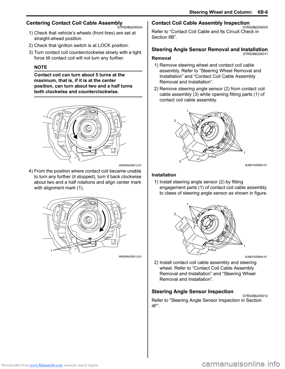
1) Check that vehicle’s wheels (front tires) are set at straight-ahead position.
2) Check that ignition swit ch is at LOCK position.
3) Turn contact coil counterclockwise slowly with a light force till contact coil will not turn any further.
NOTE
Contact coil can turn about 5 turns at the
maximum, that is, if it is at the center
position, can turn about two and a half turns
both clockwise and counterclockwise.
4) From the position where contact coil became unable to turn any further (it stopped), turn it back clockwise
about two and a half rotations and align center mark
with alignment mark (1).
Contact Coil Cable Assembly InspectionS7RS0B6206005
Refer to “Contact Coil Cable and Its Circuit Check in
Section 8B”.
Steering Angle Sensor Removal and InstallationS7RS0B6206011
Removal
1) Remove steering wheel and contact coil cable assembly. Refer to “Ste ering Wheel Removal and
Installation” and “Contact Coil Cable Assembly
Removal and Installation”.
2) Remove steering angle sensor (2) from contact coil cable assembly (3) while op ening fitting parts (1) of
contact coil cable assembly.
Installation 1) Install steering angle sensor (2) by fitting engagement parts (1) of contact coil cable assembly
to claws of steering angle sensor as shown in figure.
2) Install contact coil cable assembly and steering wheel. Refer to “Contact Coil Cable Assembly
Removal and Installation” and “Steering Wheel
Removal and Installation”.
Steering Angle Sensor InspectionS7RS0B6206012
Refer to “Steering Angle Sens or Inspection in Section
4F”.
I4RS0A620012-01
1
I4RS0A620013-01
1
1
2
3I6JB01620003-01
1
1
2
I6JB01620004-01
Page 890 of 1496

Downloaded from www.Manualslib.com manuals search engine 6C-8 Power Assisted Steering System:
Step 2: DTC Check, Record and Clearance
First, check DTC, referring to “DTC Check”. If DTC is
indicated, print it or write them down and then clear them
by referring to “DTC Clearance”. DTC indicates
malfunction that occurred in the system but does not
indicate whether it exists now or it occurred in the past
and the normal condition has been restored now. To
check which case applies, check the symptom in
question according to Step 5 and recheck DTC
according to Step 6 and 7.
Attempt to diagnose a trouble based on DTC in this step
only or failure to clear the DTC in this step will lead to
incorrect diagnosis, trouble diagnosis of a normal circuit
or difficulty in troubleshooting.
Step 3 and 4: Visual Inspection
As a preliminary step, be sure to perform visual check of
the items that support proper function of the P/S system
referring to “Visual Inspection”.
Step 5: Trouble Symptom Confirmation
Based on information obtained in “Step 1: Customer
Complaint Analysis: ” and “S tep 2: DTC Check, Record
and Clearance: ”, confirm trouble symptoms. Also,
reconfirm trouble symptom by performing test drive and
turning steering wheel fully to right and left at stopped
vehicle.
Step 6 and 7: Rechecking and Record of DTC
Refer to “DTC Check” for checking procedure.
Step 8: Steering Symptom Diagnosis and P/S
System Symptom Diagnosis
Perform basic steering system check according to
“Steering Symptom Diagnosis in Section 6A” first. When
the end of the flow has been reached, check the parts of
the system suspected as a possible cause referring to
“P/S System Symptom Diagnosis” and based on
symptoms appearing on the vehicle (symptoms obtained
through steps of customer complaint analysis, trouble
symptom confirmation and/or basic P/S system check)
and repair or replace faulty parts, if any.
Step 9: Troubleshooting for DTC (See each DTC
Diag. Flow)
Based on the DTC indicated in Step 6 or 7 and referring
to the applicable DTC diag. flow, locate the cause of the
trouble, namely in a sensor, switch, wire harness,
connector, actuator, P/S control module or other part and
repair or replace faulty parts.
Step 10: Intermittent Problems Check
Check parts where an intermittent trouble is easy to
occur (e.g., wire harness, connector, etc.), referring to
“Intermittent and Poor Connection Inspection in Section
00” and related circuit of DTC recorded in Step 2. Step 11: Final Confirmation Test
Confirm that the problem symptom has gone and the P/
S system is free from any abnormal conditions. If what
has been repaired is related to the DTC, clear the DTC
once, perform DTC confirmation procedure and confirm
that no DTC is indicated.
“EPS” Warning Light CheckS7RS0B6304002
1) Turn ignition switch to ON position (without engine
running) and chec k if the “EPS” warning light (1)
lights up. If the light dose not light up, go to ““EPS”
Warning Light Does Not Come ON with Ignition
Switch Turned ON before Engine Starts” of the
diagnostic flows.
2) Start engine and check if the “EPS” warning light turns OFF. If light remains ON and no DTC is stored
in P/S control module, go to ““EPS” Warning Light
Remains ON Steady after Engine Starts” for
troubleshooting.
DTC CheckS7RS0B6304003
1) Turn ignition switch to OFF position.
2) Connect SUZUKI scan tool to data link connector (DLC) (1) located on underside of instrument panel
at driver’s seat side.
Special tool
(A): SUZUKI scan tool
1
I6RS0C630002-01
(A)
1
I4RS0B450003-01
Page 891 of 1496

Downloaded from www.Manualslib.com manuals search engine Power Assisted Steering System: 6C-9
3) Start engine.
4) Read DTC according to the instructions displayed on
SUZUKI scan tool. For further details, refer to
operator’s manual for SUZUKI scan tool.
NOTE
• If communication between SUZUKI scan tool and the vehicle can not be
established, perform “Serial Data Link
Circuit Check”.
• DTC C1122 (engine speed signal failure) is indicated when ignition switch is at ON
position and engine is not running, but it
means there is nothing abnormal if
indication changes to a normal one when
engine is started.
5) After completing the check, turn ignition switch to
OFF position and disconnect SUZUKI scan tool from
DLC.
DTC ClearanceS7RS0B6304004
1) Turn ignition switch to OFF position.
2) Connect SUZUKI scan tool to data link connector (DLC) (1) located on underside of instrument panel
at driver’s seat side.
Special tool
(A): SUZUKI scan tool
3) Turn ignition switch to ON position.
4) Erase DTC according to the instructions displayed on SUZUKI scan tool. For further details, refer to
operator’s manual for SUZUKI scan tool.
5) After completing the clearance, turn ignition switch to OFF position and disconnect SUZUKI scan tool from
DLC.
DTC TableS7RS0B6304005
CAUTION!
Be sure to perform the “EPS Syst em Check” before starting troubleshooting corresponding to each
DTC.
(A)
1
I4RS0B450003-01
DTC No. Detecting item Detecting condition
(DTC will set when detecting) Trouble area MIL
No
CODES Normal — — —
�) C1113 Steering torque sensor (Main
and Sub) circuit correlation Voltage difference between torque
sensor main signal and sub signal
is more than 0.6 V for 1 second
continuously. • Torque sensor signal circuit
• Torque sensor
• P/S control module
1 driving
cycle
�) C1114 Steering torque sensor
reference power supply
circuit Circuit voltage of torque sensor 5
V reference power supply voltage
is more than 5.7 V or less than 4.3
V for 1 second continuously. • Torque sensor circuit
• Torque sensor
• P/S control module
1 driving
cycle
�) C1117 Steering torque sensor
failure signal circuit low Torque sensor internal failure
signal circuit voltage is less than
1.7 V when ignition switch turned
ON.
• Torque sensor signal circuit
• Torque sensor
• P/S control module1 driving
cycle
�) C1118 Steering torque sensor
failure signal circuit high Torque sensor internal failure
signal circuit voltage is more than
3.7 V for 1 second continuously. 1 driving
cycle
�) C1119 Steering torque sensor
power supply circuit Circuit voltage of torque sensor
main power supply
is less than
7.5 V for 1 second continuously. • Torque sensor circuit
• Torque sensor
• P/S control module
1 driving
cycle
Page 918 of 1496

Downloaded from www.Manualslib.com manuals search engine 6C-36 Power Assisted Steering System:
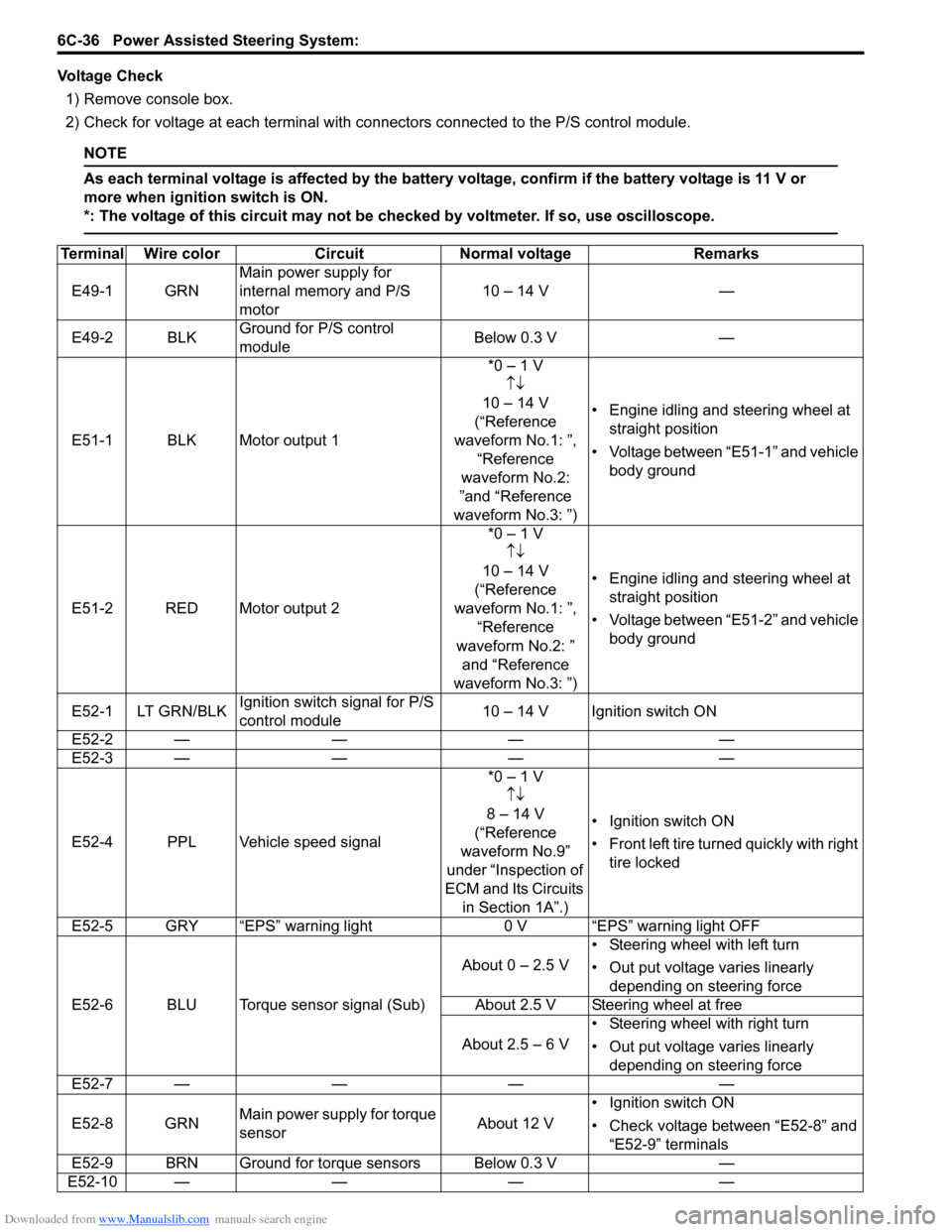
Voltage Check1) Remove console box.
2) Check for voltage at each terminal with co nnectors connected to the P/S control module.
NOTE
As each terminal voltage is affected by the battery voltage, confirm if the battery voltage is 11 V or
more when ignition switch is ON.
*: The voltage of this circuit may not be checked by voltmeter. If so, use oscilloscope.
Terminal Wire colorCircuit Normal voltage Remarks
E49-1 GRN Main power supply for
internal memory and P/S
motor 10 – 14 V
—
E49-2 BLK Ground for P/S control
module Below 0.3 V
—
E51-1 BLK Motor output 1 *0 – 1 V
↑↓
10 – 14 V
(“Reference
waveform No.1: ”, “Reference
waveform No.2:
”and “Reference
waveform No.3: ”) • Engine idling and steering wheel at
straight position
• Voltage between “E51-1” and vehicle body ground
E51-2 RED Motor output 2 *0 – 1 V
↑↓
10 – 14 V
(“Reference
waveform No.1: ”, “Reference
waveform No.2: ” and “Reference
waveform No.3: ”) • Engine idling and steering wheel at
straight position
• Voltage between “E51-2” and vehicle body ground
E52-1 LT GRN/BLK Ignition switch signal for P/S
control module 10 – 14 V Ignition switch ON
E52-2 — —— —
E52-3 — —— —
E52-4 PPL Vehicle speed signal *0 – 1 V
↑↓
8 – 14 V
(“Reference
waveform No.9”
under “Inspection of
ECM and Its Circuits in Section 1A”.) • Ignition switch ON
•Front left tire tu
rned quickly with right
tire locked
E52-5 GRY “EPS” warning light 0 V “EPS” warning light OFF
E52-6 BLU Torque sensor signal (Sub) About 0 – 2.5 V
• Steering wheel with left turn
• Out put voltage varies linearly
depending on steering force
About 2.5 V Steering wheel at free
About 2.5 – 6 V • Steering wheel with right turn
• Out put voltage varies linearly
depending on steering force
E52-7 — —— —
E52-8 GRN Main power supply for torque
sensor About 12 V• Ignition switch ON
• Check voltage between “E52-8” and
“E52-9” terminals
E52-9 BRN Ground for torque sensors Below 0.3 V —
E52-10 — —— —
Page 934 of 1496

Downloaded from www.Manualslib.com manuals search engine 7-ii Table of Contents
Recommended Service Material ....................... 7B-33
Special Tool ...................................................... 7B-33
Automatic Type .................... .................................7B-34
Precautions.........................................................7B-34 A/C System Caution .......................................... 7B-34
Precautions in Diagnosing Trouble ................... 7B-34
Precautions on Servicing A/C System .............. 7B-34
General Description .......... .................................7B-34
Auto A/C System Descript ion ............................ 7B-34
HVAC Control Module Operation Description ... 7B-36
Refrigerant Type Identifica tion .......................... 7B-36
Sub-Cool A/C System Description .................... 7B-36
A/C Operation Description ................................ 7B-36
On-Board Diagnostic System Description ......... 7B-37
Schematic and Routing Diagram ......................7B-37 Major Components of A/C System .................... 7B-37
A/C System Wiring Diagra m ............................. 7B-38
Diagnostic Information and Procedures ..........7B-39 A/C System Symptom Diagnosis ...................... 7B-39
Abnormal Noise Sympto m Diagnosis of A/C
System ............................................................ 7B-42
DTC Check........................................................ 7B-42
DTC Clearance ................................................. 7B-43
DTC Table ......................................................... 7B-44
Fail-Safe Table ................. ................................. 7B-45
Scan Tool Data ................................................. 7B-46
Air Conditioning System Check......................... 7B-47
Visual Inspection ............................................... 7B-49
DTC B1502: Inside Air Temperature Sensor and/or Its Circuit Malfunction .......................... 7B-49
DTC B1503: A/C Evaporator Air Temperature Sensor and/or Its Circuit Malfunction .............. 7B-50
DTC B1504: Sunload Sensor and/or Its Circuit Malfunction ......... ................................. 7B-52
DTC B1511: Temperature Control Actuator (Position Sensor) and/or Its Circuit
Malfunction ...................................................... 7B-53
DTC B1512: Air flow Control Actuator (Position Sensor) and/or Its Circuit
Malfunction ...................................................... 7B-55
DTC B1513: Temperature Control Actuator and/or Its Circuit Malfunction .......................... 7B-57
DTC B1514: Air Flow Co ntrol Actuator and/or
Its Circuit Malfunction ...................................... 7B-60
DTC B1541: HVAC Control Module Back-Up Power Supply Malfunction .............................. 7B-62
DTC B1546: A/C Refrigerant Pressure Malfunction ...................................................... 7B-63
DTC B1551: Serial Communication Circuit Malfunction ...................................................... 7B-63
DTC B1552: Serial Communication Signal Malfunction ...................................................... 7B-64
DTC B1553: CAN Communication Signal Malfunction ...................................................... 7B-65
DTC B1557: Vehicle Speed Sensor Signal Malfunction ...................................................... 7B-65
DTC B1561: Engine Coolant Temperature Sensor Signal Malfunctio n .............................. 7B-66 DTC B1562: Outside Air Temperature Sensor
Signal Malfunction ........................................... 7B-66
DTC B1563: A/C Refr igerant Pressure
Sensor Signal Malfunction .............................. 7B-66
Inspection of HVAC Control Module and Its Circuit .............................................................. 7B-67
A/C System Performance Inspection ................ 7B-70
A/C System Inspection at ECM ......................... 7B-70
Repair Instructions ............ ................................7B-71
Operation Procedure for Refrigerant Charge .... 7B-71
HVAC Unit Components ................................... 7B-72
HVAC Unit Removal and In stallation ................ 7B-73
Temperature Control Actuator Removal and Installation ....................................................... 7B-73
Temperature Control Actuat or Inspection ......... 7B-73
Air Flow Control Actuator Removal and Installation ....................................................... 7B-74
Air Flow Control Actuator Inspection ................. 7B-74
Air Intake Control Actuator Removal and Installation ....................................................... 7B-75
Air Intake Control Actuator Inspection............... 7B-75
Actuator Linkage Inspection .............................. 7B-76
Blower Motor Controller Removal and Installation ....................................................... 7B-76
Blower Motor Controller Inspection ................... 7B-76
HVAC Control Module Removal and Installation ....................................................... 7B-77
Sunload Sensor Removal and Installation ........ 7B-77
Sunload Sensor Inspection ............................... 7B-77
Outside Air Temperature Sensor Removal and Installation ................................................ 7B-77
Outside Air Temperature Sensor Inspection ..... 7B-77
Inside Air Temperature Sensor Removal and Installation ....................................................... 7B-78
Inside Air Temperature Sens or Inspection ........ 7B-78
Condenser Assembly On-Vehicle Inspection .... 7B-78
Condenser Assembly Removal and Installation ....................................................... 7B-78
Receiver/Dryer Removal and Installation .......... 7B-78
Evaporator Inspection ....................................... 7B-78
Evaporator Temperature Sensor Removal and Installation ................................................ 7B-78
Evaporator Temperature Se nsor Inspection ..... 7B-78
Expansion Valve Removal an d Installation ....... 7B-78
Expansion Valve Inspection .............................. 7B-78
A/C Refrigerant Pressure Sensor and Its Circuit Inspection............................................. 7B-78
A/C Refrigerant Pressu re Sensor Removal
and Installation ................................................ 7B-78
Compressor Relay Inspection .
.......................... 7B-78
Compressor Drive Belt Inspection and Adjustment ...................................................... 7B-78
Compressor Drive Belt Removal and Installation ....................................................... 7B-79
Compressor Assembly Removal and Installation ....................................................... 7B-79
Compressor Assembly Components................. 7B-79
Magnet Clutch Removal and Installation........... 7B-79
Magnet Clutch Inspection.................................. 7B-79
Relief Valve Inspection...................................... 7B-79
Page 957 of 1496

Downloaded from www.Manualslib.com manuals search engine Air Conditioning System: Manual Type 7B-9
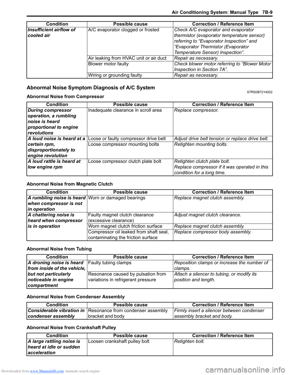
Abnormal Noise Symptom Diagnosis of A/C SystemS7RS0B7214002
Abnormal Noise from Compressor
Abnormal Noise from Magnetic Clutch
Abnormal Noise from Tubing
Abnormal Noise from Condenser Assembly
Abnormal Noise from Crankshaft PulleyInsufficient airflow of
cooled air
A/C evaporator clogged or frosted
Check A/C evaporator and evaporator
thermistor (evaporator temperature sensor)
referring to “Evaporator Inspection” and
“Evaporator Thermistor (Evaporator
Temperature Sensor) Inspection”.
Air leaking from HVAC unit or air duct Repair as necessary.
Blower motor faulty Check blower motor referring to “Blower Motor
Inspection in Section 7A”.
Wiring or grounding faulty Repair as necessary.
Condition Possible cause Correction / Reference Item
Condition
Possible cause Correction / Reference Item
During compressor
operation, a rumbling
noise is heard
proportional to engine
revolutions Inadequate clearance in scroll area
Replace compressor.
A loud noise is heard at a
certain rpm,
disproportionately to
engine revolution Loose or faulty compressor drive belt
Adjust drive belt tension or replace drive belt.
Loose compressor mounting bolts Retighten mounting bolts.
A loud rattle is heard at
low engine rpm Loose compressor clutch plate bolt
Retighten clutch plate bolt.
Replace compressor if it was operated in this
condition for a long time.
Condition Possible cause Correction / Reference Item
A rumbling noise is heard
when compressor is not
in operation Worn or damaged bearings
Replace magnet clutch assembly.
A chattering noise is
heard when compressor
is in operation Faulty magnet clutch clearance
(excessive clearance)
Adjust magnet clutch clearance.
Worn magnet clutch friction surface Replace magnet clutch assembly.
Compressor oil leaked from shaft seal,
contaminating the friction surface Replace compressor body assembly.
Condition
Possible cause Correction / Reference Item
A droning noise is heard
from inside of the vehicle,
but not particularly
noticeable in engine
compartment Faulty tubing clamps
Reposition clamps or increase the number of
clamps.
Resonance caused by pulsation from
variations in re frigerant pressure Attach a silencer to tubing, or modify its
position and length.
Condition
Possible cause Correction / Reference Item
Considerable vibration in
condenser assembly Resonance from condenser assembly
bracket and body Firmly insert a silenc
er between condenser
assembly bracket and body.
Condition Possible cause Correction / Reference Item
A large rattling noise is
heard at idle or sudden
acceleration Loosen crankshaft pulley bolt
Retighten bolt.
Page 974 of 1496

Downloaded from www.Manualslib.com manuals search engine 7B-26 Air Conditioning System: Manual Type
Expansion Valve Removal and InstallationS7RS0B7216010
Removal1) Recover refrigerant fr om the A/C system with
recovery and recycling equipment referring to
“Recovery” in “Operation Procedure for Refrigerant
Charge”.
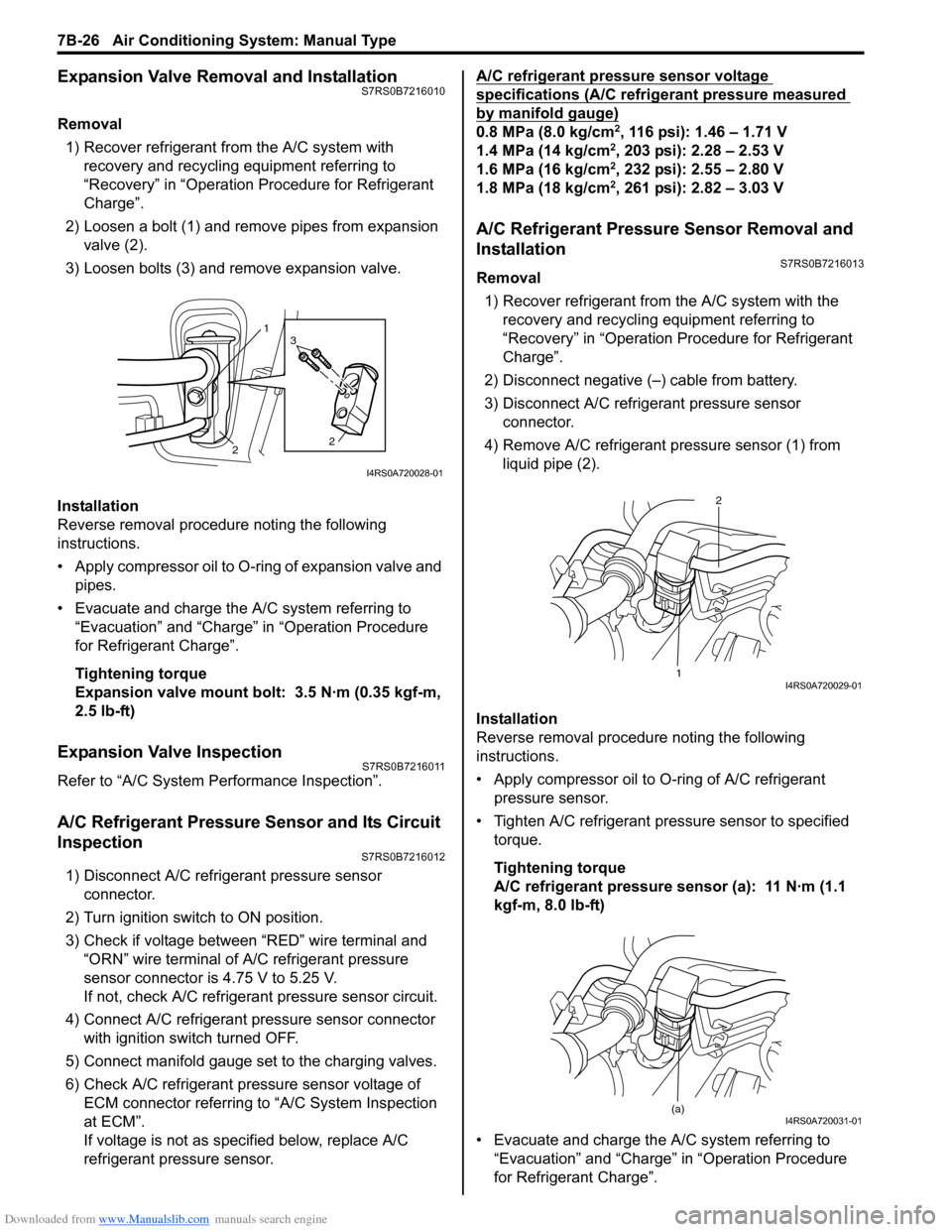
2) Loosen a bolt (1) and remove pipes from expansion valve (2).
3) Loosen bolts (3) and remove expansion valve.
Installation
Reverse removal procedure noting the following
instructions.
• Apply compressor oil to O-ring of expansion valve and pipes.
• Evacuate and charge the A/C system referring to “Evacuation” and “Charge” in “Operation Procedure
for Refrigerant Charge”.
Tightening torque
Expansion valve mount bolt: 3.5 N·m (0.35 kgf-m,
2.5 lb-ft)
Expansion Valve InspectionS7RS0B7216011
Refer to “A/C System Performance Inspection”.
A/C Refrigerant Pressure Sensor and Its Circuit
Inspection
S7RS0B7216012
1) Disconnect A/C refrigerant pressure sensor connector.
2) Turn ignition switch to ON position.
3) Check if voltage between “RED” wire terminal and “ORN” wire terminal of A/C refrigerant pressure
sensor connector is 4.75 V to 5.25 V.
If not, check A/C refrigerant pressure sensor circuit.
4) Connect A/C refrigerant pressure sensor connector with ignition switch turned OFF.
5) Connect manifold gauge set to the charging valves.
6) Check A/C refrigerant pressure sensor voltage of ECM connector referring to “A/C System Inspection
at ECM”.
If voltage is not as specified below, replace A/C
refrigerant pressure sensor. A/C refrigerant pressure sensor voltage
specifications (A/C refrigerant pressure measured
by manifold gauge)
0.8 MPa (8.0 kg/cm2, 116 psi): 1.46 – 1.71 V
1.4 MPa (14 kg/cm2, 203 psi): 2.28 – 2.53 V
1.6 MPa (16 kg/cm2, 232 psi): 2.55 – 2.80 V
1.8 MPa (18 kg/cm2, 261 psi): 2.82 – 3.03 V
A/C Refrigerant Pressure Sensor Removal and
Installation
S7RS0B7216013
Removal
1) Recover refrigerant from the A/C system with the recovery and recycling equipment referring to
“Recovery” in “Operation Procedure for Refrigerant
Charge”.
2) Disconnect negative (–) cable from battery.
3) Disconnect A/C refrigerant pressure sensor connector.
4) Remove A/C refrigerant pressure sensor (1) from liquid pipe (2).
Installation
Reverse removal procedure noting the following
instructions.
• Apply compressor oil to O-ring of A/C refrigerant
pressure sensor.
• Tighten A/C refrigerant pressure sensor to specified torque.
Tightening torque
A/C refrigerant pressure sensor (a): 11 N·m (1.1
kgf-m, 8.0 lb-ft)
• Evacuate and charge the A/C system referring to “Evacuation” and “Charge” in “Operation Procedure
for Refrigerant Charge”.
1
2 2
3
I4RS0A720028-01
1 2I4RS0A720029-01
(a)I4RS0A720031-01
Page 982 of 1496

Downloaded from www.Manualslib.com manuals search engine 7B-34 Air Conditioning System: Automatic Type
Automatic Type
Precautions
A/C System CautionS7RS0B7220001
Refer to “A/C System Caution”.
Precautions in Diagnosing TroubleS7RS0B7220002
• Do not disconnect couplers from HVAC control module, battery cable from battery, HVAC control module ground
wire harness from body or main fuse before confirming diagnostic information (diagnostic trouble code) stored in
HVAC control module memory.
• Diagnostic information (diagnostic trouble code) stored in HVAC control module can be checked by display of HVAC
control module. Also, it can be checked by using SU ZUKI scan tool. Before checking diagnostic information
(diagnostic trouble code), read this manual and operator's manual for SUZUKI scan tool to know how to read
diagnostic information (diagnostic trouble code).
• When trouble is diagnosed using diagnostic information (diagnostic trouble code) on display of HVAC control
module, keep in your mind that each diagnostic inform ation (diagnostic trouble code) has priority, and only
diagnostic information (diagnostic troub le code) which has the highest priority is indicated. Therefore, after
troubleshooting the malfunction, make sure if there exists any other diagnostic information (diagnostic trouble
code).
• Be sure to read “Precautions for Electrical Circuit Service in Section 00” before inspection.
Precautions on Servicing A/C SystemS7RS0B7220003
Refer to “Precautions on Servicing A/C System”.
General Description
Auto A/C System DescriptionS7RS0B7221001
The automatic type air conditioning system (auto A/C) is pr ovided with the function to automatically control the inside
air temperature, fan speed, air flow outl et direction and air intake position by HVAC control module in addition to
functions of the manual type air conditioning system (manua l A/C). Once the inside air temperature is set using the
temperature selector, HVAC control module automatically controls the inside air temperature at the constant level at all
times based on the inside air temperature, outside ai r temperature, amount of sunlight and engine coolant
temperature detected respectively by the inside air te mperature sensor, outside air temperature sensor, sunload
sensor and ECT sensor. At this time, “FULL AUTO A/ C” appears on the display of HVAC control module.
With the air intake selector pushed in the above state, it is possible to select any position of the air intake actuator.
Then, “FULL AUTO A/C” on the display changes to “AUTO A/C”.