2007 SUZUKI SWIFT Valve
[x] Cancel search: ValvePage 308 of 1496

Downloaded from www.Manualslib.com manuals search engine 1D-23 Engine Mechanical:
8) Install new O-ring (1) to oil gallery pipes No.2 (2) and
No.3 (3).
9) Install oil gallery pipes No.2 and No.3 to cylinder
head (4) and timing chain cover (5).
Tighten bolts to specified torque.
Tightening torque
Oil gallery pipe No.2 and No.3 bolt (a): 11 N·m (
1.1 kgf-m, 8.0 lb-ft)
10) Install water pump pulley. 11) Install cylinder head cover referring to “Cylinder Head Cover Removal and Installation”.
12) Install oil pan referring to “Oil Pan and Oil Pump
Strainer Removal and Installation in Section 1E”.
13) Install crankshaft pulley (1). Tighten bolt (2) to specified torque. To lock crankshaft pulley, use
special tool with it as shown in figure.
Special tool
(A): 09917–68221
Tightening torque
Crankshaft pulley bolt (a): 150 N·m (15.0 kgf-m,
108.5 lb-ft)
14) Install engine assembly to vehicle referring to “Engine Assembly Removal and Installation”.
Timing Chain Cover InspectionS7RS0B1406014
Oil Seal
Check oil seal lip for fault or other damage. Replace as
necessary. Timing Chain Cover
Inspect strainer (1) of oil passage for driving intake cam
timing sprocket assembly (VVT actuator).
If clog or foreign matter exists, clean strainer.
Oil Control Valve Removal and InstallationS7RS0B1406015
Removal
Remove oil gallery pipe No.1
(1) and oil control valve (2)
from timing chain cover (3).
Installation
1) Install new O-ring (4) to oil control valve.
2) Install oil control valve to timing chain cover. Tighten nuts to specification.
Tightening torque
Oil control valve mounting nut (a): 11 N·m (1.1
kgf-m, 8.0 lb-ft)
3) Install oil gallery pipe No .1 with new copper washers
(5) to timing chain cover.
Tighten bolts to specification.
Tightening torque
Oil gallery pipe No.1 bolt (b): 30 N·m (3.0 kgf-m,
21.5 lb-ft)
(a)
(a) 1
2
3
4
5
I3RH0B140027-01
I2RH0B140056-01
1
I3RH0B140028-01
1
5
(b) 3
(a)
2 4
5
I3RM0A140027-01
Page 309 of 1496

Downloaded from www.Manualslib.com manuals search engine Engine Mechanical: 1D-24
Oil Control Valve InspectionS7RS0B1406016
Oil Control Valve1) Inspect strainer (1) and mating surface (2) of oil control valve for clog or damage. Clean oil control
valve if clog or foreign matter is present on strainer
or mating surface of oil control valve.
Replace oil control valve if its mating surface is
damaged.
2) Check resistance between terminals of oil control
valve.
Oil control valve resistance
6.7 – 7.7 Ω (at 20 °C (68 °F)) Oil Gallery Pipe
Inspect oil gallery pipes No
.1, No.2 (2) and No.3 (3).
Replace if crack, deformation or clog exists.
Timing Chain and Chain Tensioner ComponentsS7RS0B1406017
1
2
I3RM0A140028-01
1
3
2
I3RH0B140030-01
I4RS0A140012-04
1. Crankshaft timing sprocket 5. Timing chain tensioner adjuster assembly 9. Spacer
2. Timing chain : Apply engine oil. 6. Chain tensioner adjuster mounting bolt
: 25 N⋅m (2.5 kgf-m, 18.0 lb-ft)
3. Timing chain No.1 guide : Apply engine oil to sliding surface. 7. Timing chain tensioner bolt
: 11 N⋅m (1.1 kgf-m, 8.0 lb-ft)
4. Timing chain tensioner : Apply engine oil to sliding surface. 8. Timing chain No.1 guide bolt
: 9 N⋅m (0.9 kgf-m, 6.5 lb-ft)
Page 310 of 1496

Downloaded from www.Manualslib.com manuals search engine 1D-25 Engine Mechanical:
Timing Chain and Chain Tensioner Removal
and Installation
S7RS0B1406018
Removal
CAUTION!
After timing chain is removed, never turn
crankshaft and camshafts independently
more than its allowable turning range
described in “Installation”.
If turned, interferen ce may occur between
piston and valves and valves themselves,
and parts related to piston and valves may be
damaged.
1) Remove timing chain cover referring to “Timing Chain Cover Removal and Installation”.
2) By turning crankshaft, align camshafts and crankshaft at specific position as follows.
a) Align both intake and exhaust camshaft timing sprocket marks (1) with notches (2) of cylinder
head respectively.
b) Align crankshaft sprocket key (3) with notch of cylinder block (4).
Position crankshaft sprocke t key (3) at upside of
crankshaft as shown in figure.
3) Remove timing chain tensioner adjuster assembly (5).
4) Remove timing chain tensioner (6).
5) Remove timing chain No.1 guide (7).
6) Remove timing chain (8) with crankshaft timing sprocket (9). Installation
CAUTION!
After timing chain is removed, never turn
crankshaft and camshafts independently
more than such an extent (“a”, “b”) as shown
in figure.
If turned, interferen
ce may occur between
piston and valves and valves themselves,
and parts related to piston and valves may be
damaged.
1) Check that match marks (1) on intake and exhaust camshaft timing sprockets are in match with notches
(2) on cylinder head as shown in figure.
2) Set key (3) and turn crankshaft to position key on upside of crankshaft.
3
4
1
1
2
5
67
8
9
I3RH0B140032-01
“a”: 90 °4. Camshaft (IN and EX) allowable turning range.
By marks on camshaft timing sprocket within 15 ° from notches
on cylinder head on both right and left.
“b”: 15 °5. Crankshaft allowable turning range.
By key on crankshaft, within 90 ° from top on both right and left.
“a”
“b”
“b”“b”
“b”
“a”
1
12
4
3
5
I4RS0A140021-01
Page 316 of 1496
Downloaded from www.Manualslib.com manuals search engine 1D-31 Engine Mechanical:
7) Install camshaft housing.
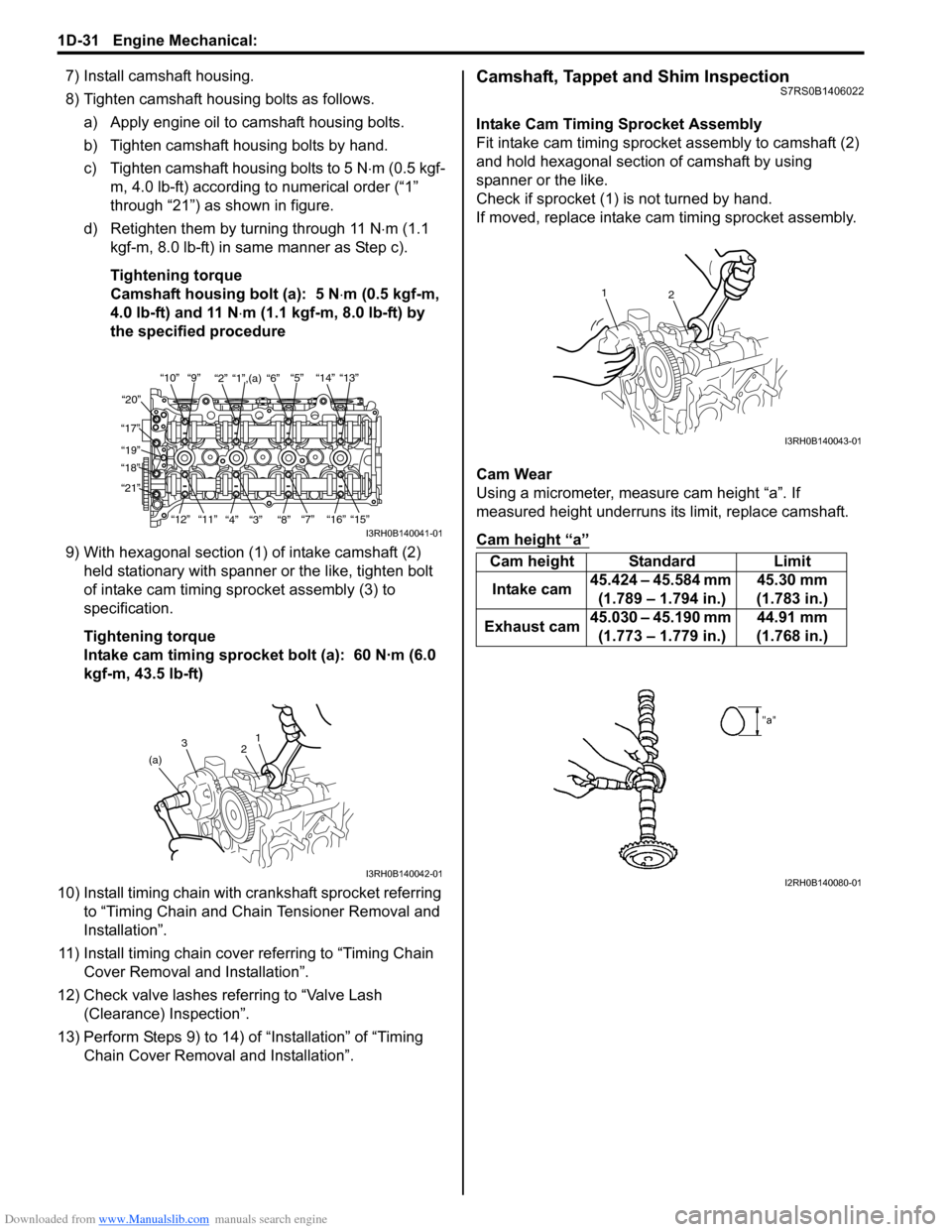
8) Tighten camshaft housing bolts as follows.a) Apply engine oil to camshaft housing bolts.
b) Tighten camshaft housing bolts by hand.
c) Tighten camshaft housing bolts to 5 N ⋅m (0.5 kgf-
m, 4.0 lb-ft) according to numerical order (“1”
through “21”) as shown in figure.
d) Retighten them by turning through 11 N⋅ m (1.1
kgf-m, 8.0 lb-ft) in same manner as Step c).
Tightening torque
Camshaft housing bolt (a): 5 N ⋅m (0.5 kgf-m,
4.0 lb-ft) and 11 N ⋅m (1.1 kgf-m, 8.0 lb-ft) by
the specified procedure
9) With hexagonal section (1) of intake camshaft (2) held stationary with spanner or the like, tighten bolt
of intake cam timing sp rocket assembly (3) to
specification.
Tightening torque
Intake cam timing sprocket bolt (a): 60 N·m (6.0
kgf-m, 43.5 lb-ft)
10) Install timing chain with cr ankshaft sprocket referring
to “Timing Chain and Chain Tensioner Removal and
Installation”.
11) Install timing chain cover referring to “Timing Chain Cover Removal and Installation”.
12) Check valve lashes referring to “Valve Lash (Clearance) Inspection”.
13) Perform Steps 9) to 14) of “Installation” of “Timing Chain Cover Removal and Installation”.Camshaft, Tappet and Shim InspectionS7RS0B1406022
Intake Cam Timing Sprocket Assembly
Fit intake cam timing sprocket assembly to camshaft (2)
and hold hexagonal section of camshaft by using
spanner or the like.
Check if sprocket (1) is not turned by hand.
If moved, replace intake ca m timing sprocket assembly.
Cam Wear
Using a micrometer, measure cam height “a”. If
measured height underruns its limit, replace camshaft.
Cam height “a”
“10”“9” “2” “1”,(a) “6” “5” “14” “13”
“20”
“17” “19”
“18”
“21”
“12”“11”
“4” “3” “8” “7” “16” “15”
I3RH0B140041-01
1
2
3
(a)
I3RH0B140042-01
Cam height Standard Limit
Intake cam 45.424 – 45.584 mm
(1.789 – 1.794 in.) 45.30 mm
(1.783 in.)
Exhaust cam 45.030 – 45.190 mm
(1.773 – 1.779 in.) 44.91 mm
(1.768 in.)
2
1
I3RH0B140043-01
I2RH0B140080-01
Page 319 of 1496
Downloaded from www.Manualslib.com manuals search engine Engine Mechanical: 1D-34
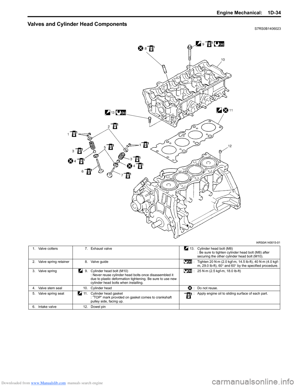
Valves and Cylinder Head ComponentsS7RS0B1406023
I4RS0A140015-01
1. Valve cotters7. Exhaust valve 13. Cylinder head bolt (M8)
: Be sure to tighten cylinder head bolt (M8) after
securing the other cylinder head bolt (M10).
2. Valve spring retainer 8. Valve guide : Tighten 20 N⋅m (2.0 kgf-m, 14.5 lb-ft), 40 N ⋅m (4.0 kgf-
m, 29.0 lb-ft), 60 ° and 60 ° by the specified procedure.
3. Valve spring 9. Cylinder head bolt (M10)
: Never reuse cylinder head bolts once disassembled it
due to plastic deformation tightening. Be sure to use new
cylinder head bolts when installing. : 25 N
⋅m (2.5 kgf-m, 18.0 lb-ft)
4. Valve stem seal 10. Cylinder head : Do not reuse.
5. Valve spring seat 11. Cylinder head gasket
: “TOP” mark provided on gasket comes to crankshaft
pulley side, facing up. : Apply engine oil to sliding surface of each part.
6. Intake valve 12. Dowel pin
Page 320 of 1496
Downloaded from www.Manualslib.com manuals search engine 1D-35 Engine Mechanical:
Valves and Cylinder Head Removal and
Installation
S7RS0B1406024
Removal1) Remove engine assembly from vehicle referring to “Engine Assembly Removal and Installation”.
2) Remove oil pan referring to “Oil Pan and Oil Pump
Strainer Removal and Installation in Section 1E”.
3) Remove cylinder head cover referring to “Cylinder Head Cover Removal and Installation”.
4) Remove timing chain cover referring to Steps 2) to 11) of “Removal” in “Tim ing Chain Cover Removal
and Installation”.
5) Remove timing chain referring to Steps 2) to 6) of “Removal” in “Timing Chain and Chain Tensioner
Removal and Installation”.
6) Remove intake and exhaust camshafts referring to Steps 3) to 8) of “Removal” in “Camshaft, Tappet and
Shim Removal and Installation”.
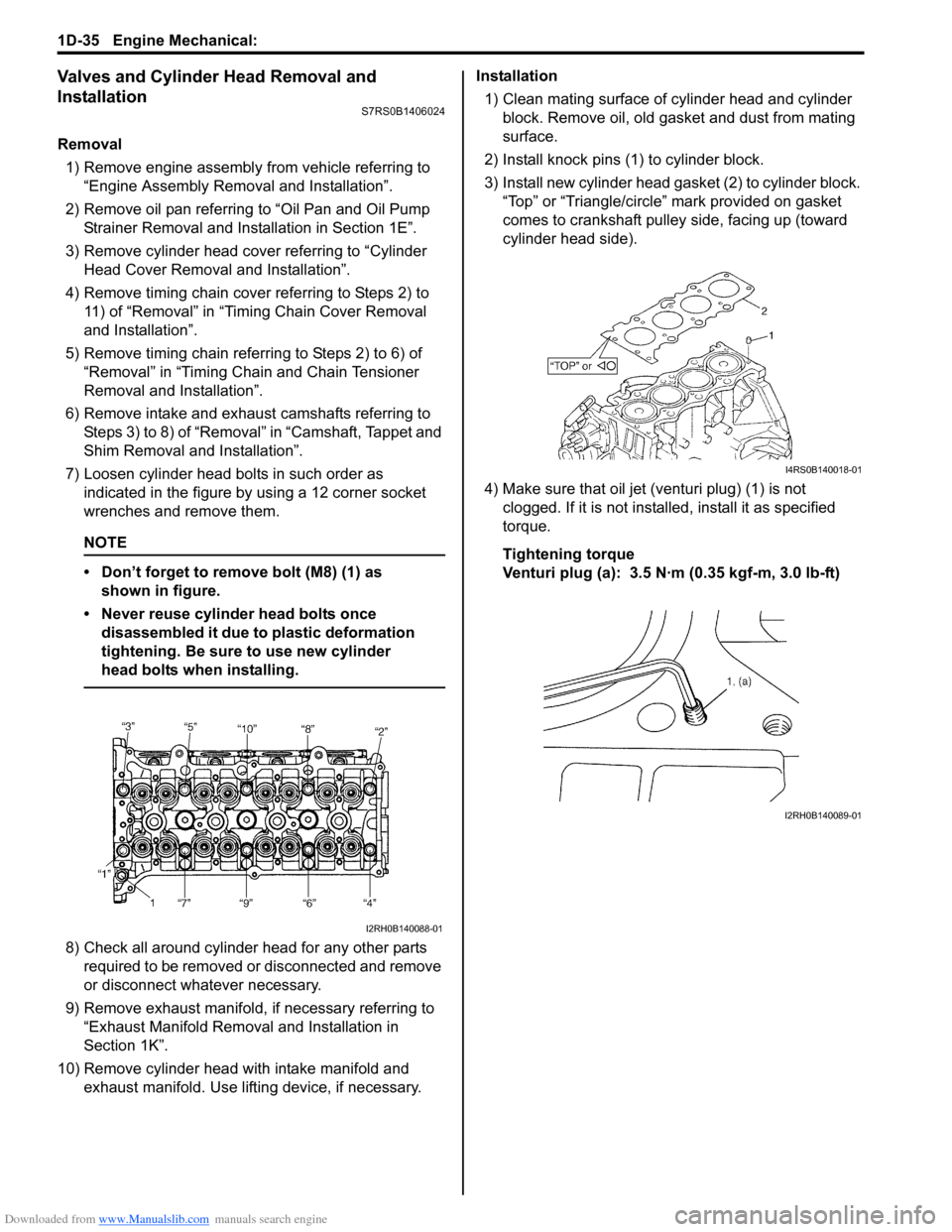
7) Loosen cylinder head bolts in such order as indicated in the figure by using a 12 corner socket
wrenches and remove them.
NOTE
• Don’t forget to remove bolt (M8) (1) as shown in figure.
• Never reuse cylinder head bolts once disassembled it due to plastic deformation
tightening. Be sure to use new cylinder
head bolts when installing.
8) Check all around cylinder head for any other parts required to be removed or disconnected and remove
or disconnect whatever necessary.
9) Remove exhaust manifold, if necessary referring to
“Exhaust Manifold Removal and Installation in
Section 1K”.
10) Remove cylinder head wi th intake manifold and
exhaust manifold. Use lifting device, if necessary. Installation
1) Clean mating surface of cylinder head and cylinder block. Remove oil, old gasket and dust from mating
surface.
2) Install knock pins (1) to cylinder block.
3) Install new cylinder head gasket (2) to cylinder block. “Top” or “Triangle/circle” mark provided on gasket
comes to crankshaft pulley side, facing up (toward
cylinder head side).
4) Make sure that oil jet (venturi plug) (1) is not clogged. If it is not install ed, install it as specified
torque.
Tightening torque
Venturi plug (a): 3.5 N·m (0.35 kgf-m, 3.0 lb-ft)
I2RH0B140088-01
I4RS0B140018-01
I2RH0B140089-01
Page 322 of 1496
Downloaded from www.Manualslib.com manuals search engine 1D-37 Engine Mechanical:
Valves and Cylinder Head Disassembly and
Assembly
S7RS0B1406025
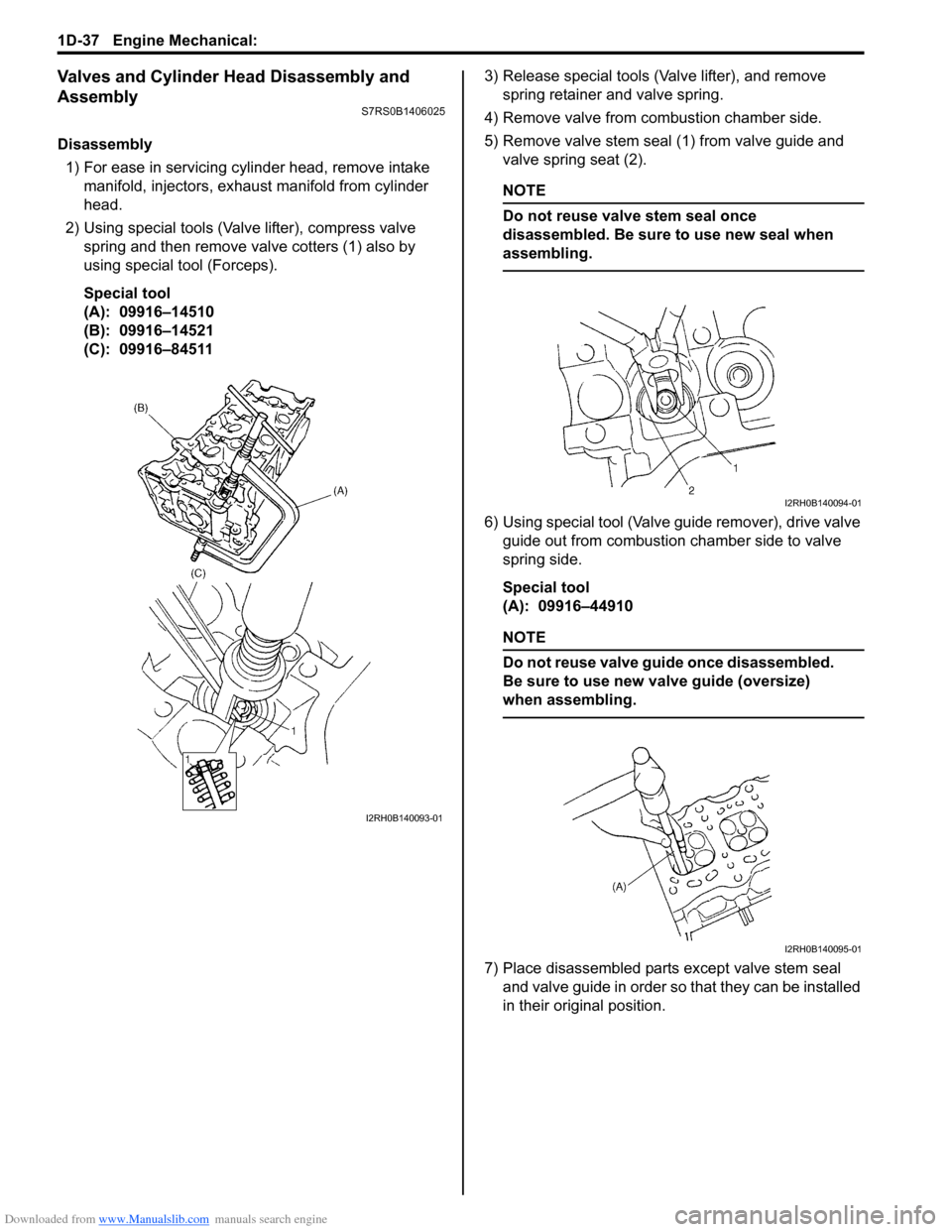
Disassembly1) For ease in servicing cylinder head, remove intake manifold, injectors, exhaust manifold from cylinder
head.
2) Using special tools (Val ve lifter), compress valve
spring and then remove valve cotters (1) also by
using special tool (Forceps).
Special tool
(A): 09916–14510
(B): 09916–14521
(C): 09916–84511 3) Release special tools (Valve lifter), and remove
spring retainer and valve spring.
4) Remove valve from combustion chamber side.
5) Remove valve stem seal (1) from valve guide and valve spring seat (2).
NOTE
Do not reuse valve stem seal once
disassembled. Be sure to use new seal when
assembling.
6) Using special tool (Valve guide remover), drive valve guide out from combustion chamber side to valve
spring side.
Special tool
(A): 09916–44910
NOTE
Do not reuse valve guide once disassembled.
Be sure to use new va lve guide (oversize)
when assembling.
7) Place disassembled parts except valve stem seal
and valve guide in order so that they can be installed
in their original position.
I2RH0B140093-01
I2RH0B140094-01
I2RH0B140095-01
Page 323 of 1496
Downloaded from www.Manualslib.com manuals search engine Engine Mechanical: 1D-38
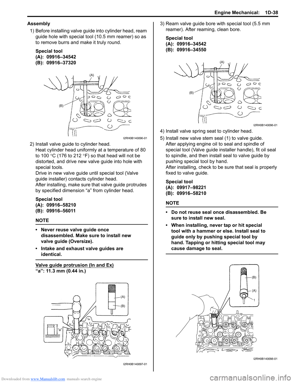
Assembly1) Before installing valve guide into cylinder head, ream
guide hole with special tool (10.5 mm reamer) so as
to remove burrs and make it truly round.
Special tool
(A): 09916–34542
(B): 09916–37320
2) Install valve guide to cylinder head. Heat cylinder head uniformly at a temperature of 80
to 100 °C (176 to 212 °F) so that head will not be
distorted, and drive new valve guide into hole with
special tools.
Drive in new valve guide until special tool (Valve
guide installer) contacts cylinder head.
After installing, ma ke sure that valve guide pr otrudes
by specified dimension “a” from cylinder head.
Special tool
(A): 09916–58210
(B): 09916–56011
NOTE
• Never reuse valve guide once disassembled. Make sure to install new
valve guide (Oversize).
• Intake and exhaust valve guides are identical.
Valve guide protrusion (In and Ex)
“a”: 11.3 mm (0.44 in.) 3) Ream valve guide bore with special tool (5.5 mm
reamer). After reaming, clean bore.
Special tool
(A): 09916–34542
(B): 09916–34550
4) Install valve spring seat to cylinder head.
5) Install new valve stem seal (1) to valve guide. After applying engine oil to seal and spindle of
special tool (Valve guide installer handle), fit oil seal
to spindle, and then install seal to valve guide by
pushing special tool by hand.
After installing, check to be sure that seal is properly
fixed to valve guide.
Special tool
(A): 09917–98221
(B): 09916–58210
NOTE
• Do not reuse seal once disassembled. Be sure to install new seal.
• When installing, never tap or hit special tool with a hammer or else. Install seal to
guide only by pushing special tool by
hand. Tapping or hitting special tool may
cause damage to seal.
I2RH0B140096-01
I2RH0B140097-01
I2RH0B140096-01
I2RH0B140098-01