Page 1118 of 1496
Downloaded from www.Manualslib.com manuals search engine 8B-80 Air Bag System:
DTC B1081 / B1091: Driver / Passenger Side-Sensor Performance ProblemS7RS0B8204038
DTC Will Set when
SDM receives internal fault signal from side-sensor.
DTC Troubleshooting1) Turn ignition switch OFF.
2) Replace driver or passenger side-sensor referr ing to “Side-Sensor Removal and Installation”.
3) Repeat “Air Bag Diagnostic System Check”.
DTC B1082 / B1092: Driver / Passenger Side-Sensor Communication ErrorS7RS0B8204039
DTC Will Set when
Side-sensor abnormal signal is detected by SDM.
DTC Troubleshooting
1) Turn ignition switch OFF.
2) Replace driver or passenger side-sensor referr ing to “Side-Sensor Removal and Installation”.
3) Repeat “Air Bag Diagnostic System Check”.
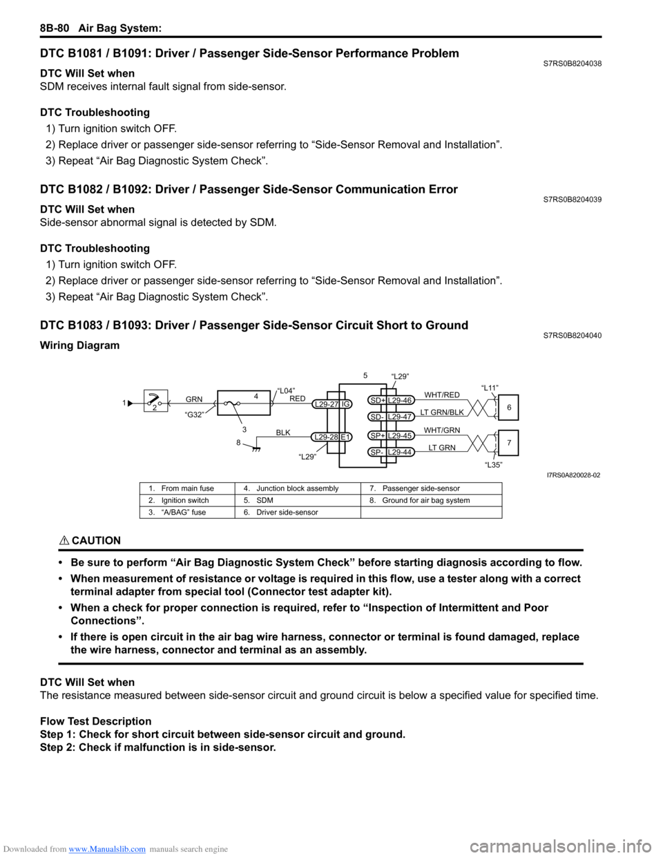
DTC B1083 / B1093: Driver / Passenger Side-Sensor Circuit Short to GroundS7RS0B8204040
Wiring Diagram
CAUTION!
• Be sure to perform “Air Bag Diagnostic System Check” before starting diagnosis according to flow.
• When measurement of resistance or voltage is required in this flow, use a tester along with a correct terminal adapter from special tool (Connector test adapter kit).
• When a check for proper connection is required, refer to “Inspection of Intermittent and Poor Connections”.
• If there is open circuit in the air bag wire harnes s, connector or terminal is found damaged, replace
the wire harness, connector and terminal as an assembly.
DTC Will Set when
The resistance measured between side-sen sor circuit and ground circuit is below a specified value for specified time.
Flow Test Description
Step 1: Check for short circuit between side-sensor circuit and ground.
Step 2: Check if malfunction is in side-sensor.
1 2
3
GRN
RED
8
BLK
L29-27
L29-28 IG
E1
4
“L29”
“L04”
“G32”
“L29”5
WHT/RED
LT GRN/BLKL29-46
SD+
L29-47
SD-6
“L11”
WHT/GRN
LT GRNL29-45
SP+
L29-44
SP-7
“L35”
I7RS0A820028-02
1. From main fuse 4. Junction blo ck assembly 7. Passenger side-sensor
2. Ignition switch 5. SDM 8. Ground for air bag system
3. “A/BAG” fuse 6. Driver side-sensor
Page 1122 of 1496
Downloaded from www.Manualslib.com manuals search engine 8B-84 Air Bag System:
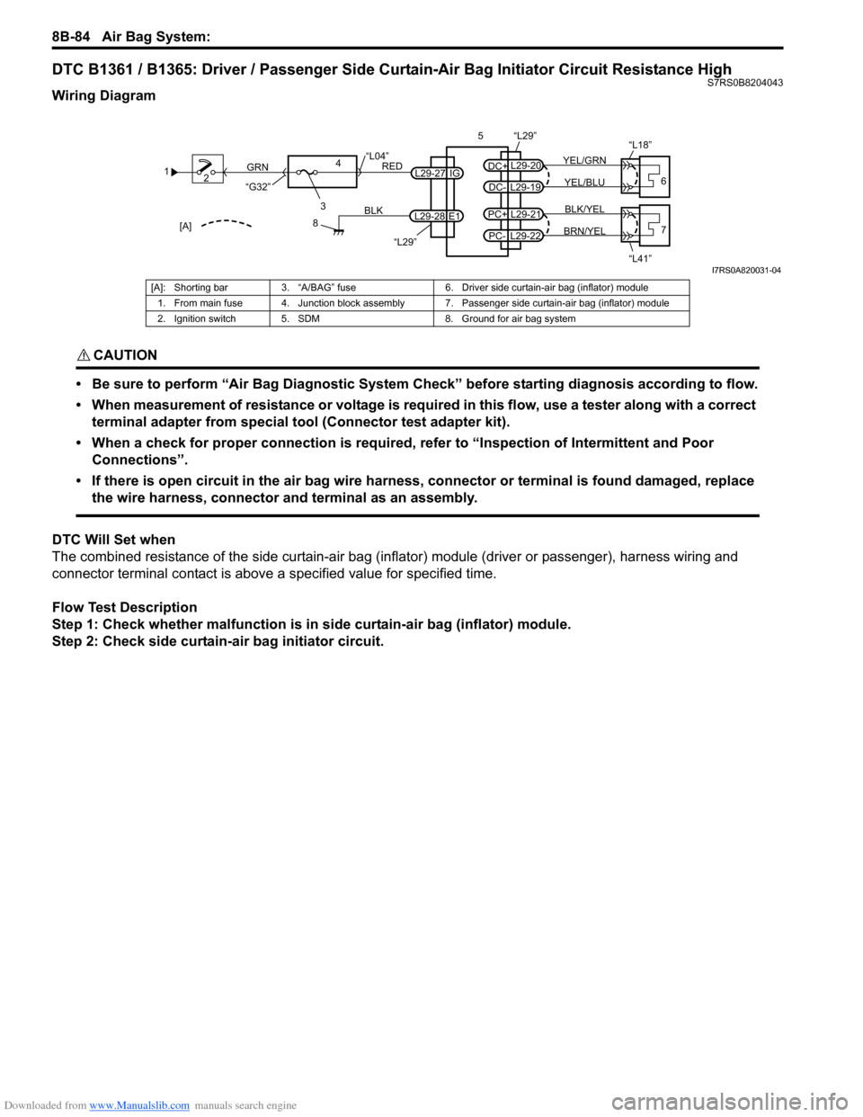
DTC B1361 / B1365: Driver / Passenger Side Curtain-Air Bag Initiator Circuit Resistance HighS7RS0B8204043
Wiring Diagram
CAUTION!
• Be sure to perform “Air Bag Diagnostic System Check” before starting diagnosis according to flow.
• When measurement of resistance or voltage is required in this flow, use a tester along with a correct terminal adapter from special tool (Connector test adapter kit).
• When a check for proper connection is required, refer to “Inspection of Intermittent and Poor Connections”.
• If there is open circuit in the air bag wire harnes s, connector or terminal is found damaged, replace
the wire harness, connector and terminal as an assembly.
DTC Will Set when
The combined resistance of the side curtain-air bag (inflator) module (driver or passenger), harness wiring and
connector terminal contact is above a specified value for specified time.
Flow Test Description
Step 1: Check whether malfunction is in side curtain-air bag (inflator) module.
Step 2: Check side curtain-air bag initiator circuit.
1 2
3
GRN
RED
8
BLK
L29-27
L29-28 IG
E1
4
“L29”
“L04”
“G32”
“L29”
L29-20
DC+
L29-19
DC-YEL/BLU
YEL/GRN
56
“L18”
L29-21
PC+
L29-22
PC-BRN/YEL BLK/YEL7
“L41”[A]
I7RS0A820031-04
[A]: Shorting bar 3. “A/BAG” fuse 6. Driver side curtain-air bag (inflator) module
1. From main fuse 4. Junction block assembly 7. Passenger side curtain-air bag (inflator) module
2. Ignition switch 5. SDM 8. Ground for air bag system
Page 1125 of 1496
Downloaded from www.Manualslib.com manuals search engine Air Bag System: 8B-87
CAUTION!
• Be sure to perform “Air Bag Diagnostic System Check” before starting diagnosis according to flow.
• When measurement of resistance or voltage is required in this flow, use a tester along with a correct terminal adapter from special tool (Connector test adapter kit).
• When a check for proper connection is required, refer to “Inspection of Intermittent and Poor Connections”.
• If there is open circuit in the air bag wire harnes s, connector or terminal is found damaged, replace
the wire harness, connector and terminal as an assembly.
DTC Will Set when
The combined resistance of the side curtain-air bag (inflator) module (driver or passenger), harness wiring and
connector terminal contact is below a specified value for specified time.
Flow Test Description
Step 1: Check whether malfunction is in side curtain-air bag (inflator) module.
Step 2: Check side curtain-air bag initiator circuit.
DTC Troubleshooting
Step Action YesNo
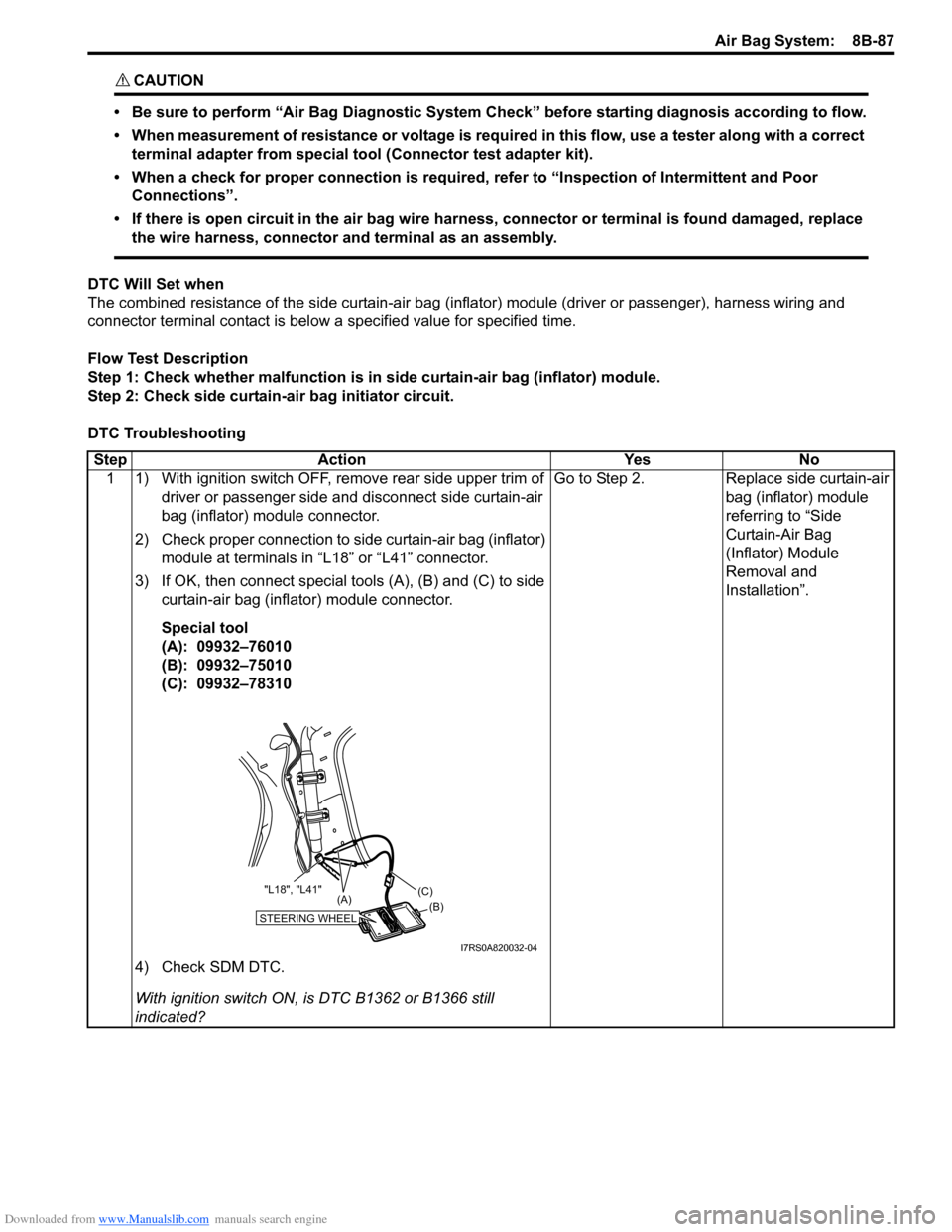
1 1) With ignition switch OFF, remove rear side upper trim of driver or passenger side and disconnect side curtain-air
bag (inflator) module connector.
2) Check proper connection to side curtain-air bag (inflator) module at terminals in “L18” or “L41” connector.
3) If OK, then connect special tools (A), (B) and (C) to side curtain-air bag (inflator) module connector.
Special tool
(A): 09932–76010
(B): 09932–75010
(C): 09932–78310
4) Check SDM DTC.
With ignition switch ON, is DTC B1362 or B1366 still
indicated? Go to Step 2.
Replace side curtain-air
bag (inflator) module
referring to “Side
Curtain-Air Bag
(Inflator) Module
Removal and
Installation”.
STEERING WHEEL(B)
(C)
(A)
"L18", "L41"
I7RS0A820032-04
Page 1133 of 1496
Downloaded from www.Manualslib.com manuals search engine Air Bag System: 8B-95
Inspection of Intermittent and Poor
Connections
S7RS0B8204048
Most intermittents are caused by faulty electrical
connections or wiring. When a check for proper
connection is requested in a diagnostic flow, perform
careful check of suspect circuits.
If any abnormality is found, repair or replace as a wire
harness assembly.
• Poor mating of connector halves, or terminals not fully seated in the connector body (backed out).
• Dirt or corrosion on the terminals. The terminals must be clean and free of any foreign material which could
impede proper terminal contact.
However, cleaning the terminal with a sand paper or
the like is prohibited.
• Damaged connector body, exposing the terminals to moisture and dirt, as well as not maintaining proper
terminal orientation with the component or mating
connector.
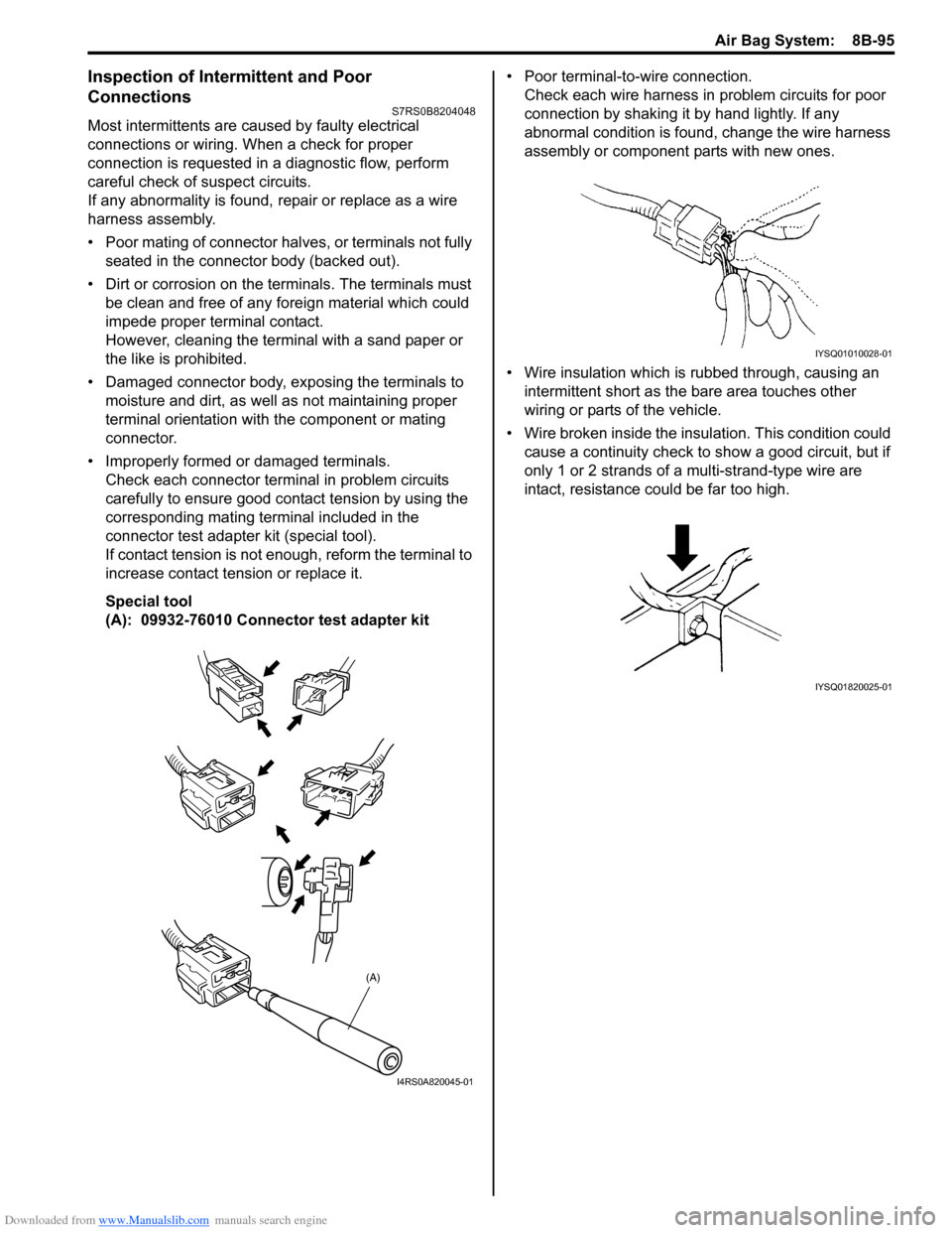
• Improperly formed or damaged terminals. Check each connector terminal in problem circuits
carefully to ensure good contact tension by using the
corresponding mating terminal included in the
connector test adapter kit (special tool).
If contact tension is not e nough, reform the terminal to
increase contact tension or replace it.
Special tool
(A): 09932-76010 Connector test adapter kit • Poor terminal-to-wire connection.
Check each wire harness in problem circuits for poor
connection by shaking it by hand lightly. If any
abnormal condition is found, change the wire harness
assembly or component parts with new ones.
• Wire insulation which is rubbed through, causing an intermittent short as the bare area touches other
wiring or parts of the vehicle.
• Wire broken inside the insulation. This condition could cause a continuity check to show a good circuit, but if
only 1 or 2 strands of a multi-strand-type wire are
intact, resistance could be far too high.
(A)
I4RS0A820045-01
IYSQ01010028-01
IYSQ01820025-01
Page 1173 of 1496
Downloaded from www.Manualslib.com manuals search engine Wiring Systems: 9A-2
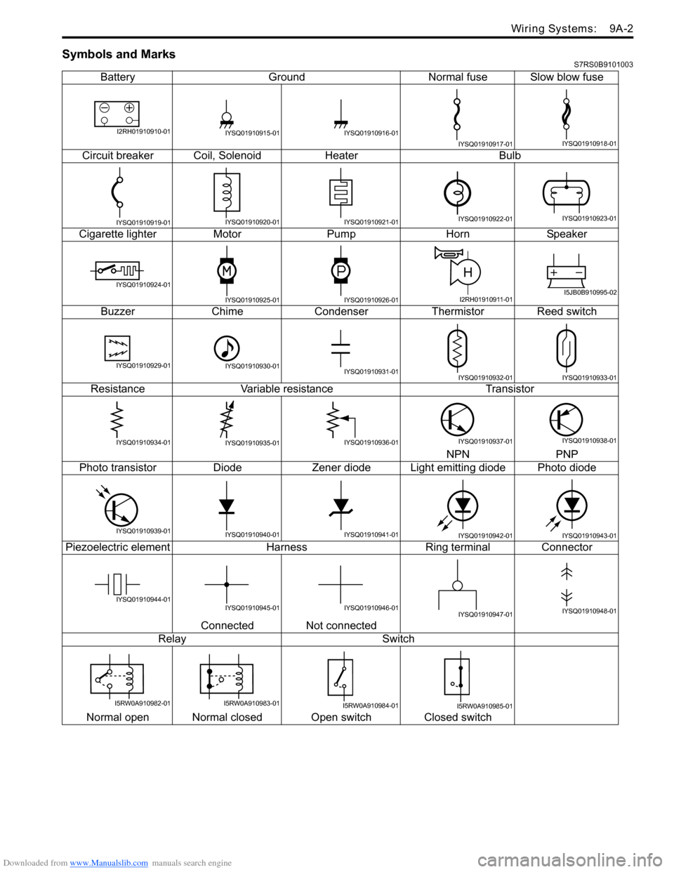
Symbols and MarksS7RS0B9101003
BatteryGroundNormal fuse Slow blow fuse
Circuit breaker Coil, SolenoidHeater Bulb
Cigarette lighter MotorPump HornSpeaker
Buzzer ChimeCondenser Thermistor Reed switch
Resistance Variable resistance Transistor
NPN PNP
Photo transistor DiodeZener diode L ight emitting diode Photo diode
Piezoelectric element Harness Ring terminal Connector
Connected Not connected
Relay Switch
Normal open Normal closed Open switch Closed switch
I2RH01910910-01IYSQ01910915-01IYSQ01910916-01
IYSQ01910917-01IYSQ01910918-01
IYSQ01910919-01IYSQ01910920-01IYSQ01910921-01IYSQ01910922-01IYSQ01910923-01
IYSQ01910924-01
IYSQ01910925-01IYSQ01910926-01
H
I2RH01910911-01I5JB0B910995-02
IYSQ01910929-01IYSQ01910930-01IYSQ01910931-01IYSQ01910932-01IYSQ01910933-01
IYSQ01910934-01IYSQ01910935-01IYSQ01910936-01IYSQ01910937-01IYSQ01910938-01
IYSQ01910939-01IYSQ01910940-01IYSQ01910941-01IYSQ01910942-01IYSQ01910943-01
IYSQ01910944-01IYSQ01910945-01IYSQ01910946-01IYSQ01910947-01IYSQ01910948-01
I5RW0A910982-01I5RW0A910983-01I5RW0A910984-01I5RW0A910985-01
Page 1175 of 1496
Downloaded from www.Manualslib.com manuals search engine Wiring Systems: 9A-4
How to Read Connector Layout DiagramS7RS0B9101004
[A-1]: Harness symbol and corresponding harness name
A: Battery harness
B: A/C harness
C: Engine harness
D: Injector harness
E: Main harness, Oil pressure switch wire, Console wire
G: Instrument panel harness
J: Side door wire (Power window)
K: Interior light harness, Rear speaker wire, Roof wire
L: Floor harness, G sensor wire (Fuel pump harness)
M: Rear bumper harness
O: Rear end door harness
Q: Air bag/Pretensioner harness
R: (Fuel pump wire)
[A-2]: Connector Number
[B]: Ground point No.
12
11
[B] [B]
Connector code
[A-1] [A-2]L 36
L13 L15
R01
L14
L12
L11L10
L09 L36
R02
L24
L25
L33
L28
L20 L26 (TO O01)
{
L05
L16
L32
L19
L01 (TO G01)
L02 (TO E04)
L03 (TO E05)
L42
R05
R04
L07 (TO K02)
I2RH01910901-01
Page 1177 of 1496
Downloaded from www.Manualslib.com manuals search engine Wiring Systems: 9A-6
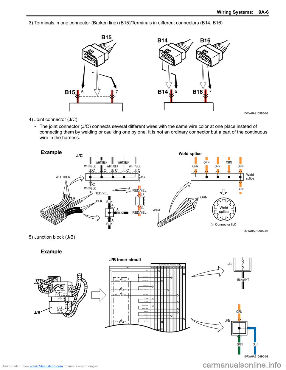
3) Terminals in one connector (Broken line) (B15)/Terminals in different connectors (B14, B16)
4) Joint connector (J/C)• The joint connector (J/C) connects several different wires with the same wire color at one place instead of
connecting them by welding or caulking one by one. It is not an ordinary connector but a part of the continuous
wire in the harness.
5) Junction block (J/B)
B15 B15
B14 B1657B14 B1657
I5RW0A910995-03
BLKBLK
A
A
A B
B
RED/YEL
WeldORN
WHT/BLK
J/C
Weld splice
BLKBLK
RED/YEL
RED/YEL
WHT/BLK
WHT/BLK
WHT/BLKWHT/BLKWHT/BLKWHT/BLKC
CCCCCWeld
splice
(in Connector list)
J/C
ORNORNORNORNORN
ORN
Weld
splice
Example
I5RW0A910989-02
IMMOBI IG IG1IG Coil, etc E39 E41E40
BCM G34
G33
G32 K01 L04 L05 L06
IG Coil
IG1
15A
MTR10A
A/B15A
2
65
13
J/B Connector No. / Terminal No.
BCM ;IG1
MTR Power, etc
A/B CONTK-LINE K-LINE
A/B SIGNAL
A/B SIGNAL
A/B SIG
A/B SIG
IG Sig 10AEPS ATMTA
4
6
1
3
24
8
11
9
12
9
11
23
25
30
29
Example
J/B
J/B
ORN
GRNBLU
J/B
J/B inner circuit
BLK/WHT
I5RW0A910990-03
Page 1181 of 1496
Downloaded from www.Manualslib.com manuals search engine Wiring Systems: 9A-10
Connector Layout Diagram
Connector Layout DiagramS7RS0B910A001
Refer to “Engine Compartment”.
Refer to “Instrument Panel”.
Refer to “Door, Roof”.
Refer to “Floor”.
Refer to “Rear”.
ESP
® is a registered trademark of Daimler Chrysler AG.
Engine CompartmentS7RS0B910A002
A: Battery cable / C: Engine harness (M13A engine, M15A engine)
A
C36
(TO E24)
C17
C18
C19 C35
(RHD A/T)
C34
(LHD A/T) C35
(LHD A/T) C34
(RHD A/T)
C37
C15
C16
C02C08
C03
C10
C0912
34
C31
C32
C33
C29
(A/T)
C28
(A/T)
C27
(A/T)C30
(M/T) C25
(A/T)
C24
C25
(M/T)
C26
C07
C06
C05
C04
C22
C21
C20 C23
C13
C12C14
C08
C01
CC40
C41C39
C38C11
A
A
B
BM15A engine, M13A engine RHD
M13A engine LHD
I6RS0C910901-01