2007 SUZUKI SWIFT door
[x] Cancel search: doorPage 1374 of 1496
Downloaded from www.Manualslib.com manuals search engine 9J-5 Hood / Fenders / Doors:
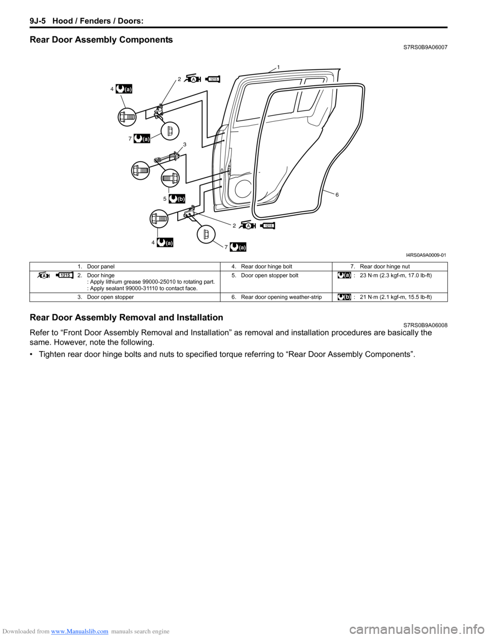
Rear Door Assembly ComponentsS7RS0B9A06007
Rear Door Assembly Removal and InstallationS7RS0B9A06008
Refer to “Front Door Assembly Removal and Installation” as removal and installation procedures are basically the
same. However, note the following.
• Tighten rear door hinge bolts and nuts to specified torque referring to “Rear Door Assembly Components”.
2
2
(a)4
(a)4
(a)7
(a)7
(b)53
6
1
I4RS0A9A0009-01
1. Door panel 4. Rear door hinge bolt7. Rear door hinge nut
2. Door hinge : Apply lithium grease 99000-25010 to rotating part.
: Apply sealant 99000-31110 to contact face. 5. Door open stopper bolt
: 23 N⋅m (2.3 kgf-m, 17.0 lb-ft)
3. Door open stopper 6. Rear door opening weather-strip: 21 N⋅m (2.1 kgf-m, 15.5 lb-ft)
Page 1375 of 1496
Downloaded from www.Manualslib.com manuals search engine Hood / Fenders / Doors: 9J-6
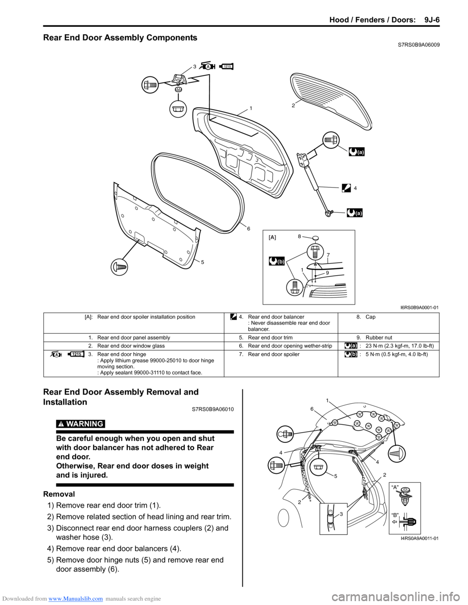
Rear End Door Assembly ComponentsS7RS0B9A06009
Rear End Door Assembly Removal and
Installation
S7RS0B9A06010
WARNING!
Be careful enough when you open and shut
with door balancer has not adhered to Rear
end door.
Otherwise, Rear end door doses in weight
and is injured.
Removal1) Remove rear end door trim (1).
2) Remove related section of head lining and rear trim.
3) Disconnect rear end door harness couplers (2) and washer hose (3).
4) Remove rear end door balancers (4).
5) Remove door hinge nuts (5) and remove rear end door assembly (6).
3
(a)
(a)
12
6
5
[A]
1
7
9
8
(b)
4
I6RS0B9A0001-01
[A]: Rear end door spoiler installation position 4. Rear end door balancer
: Never disassemble rear end door
balancer. 8. Cap
1. Rear end door panel assembly 5. Rear end door trim9. Rubber nut
2. Rear end door window glass 6. Rear end door opening wether-strip: 23 N⋅m (2.3 kgf-m, 17.0 lb-ft)
3. Rear end door hinge : Apply lithium grease 99000-25010 to door hinge
moving section.
: Apply sealant 99000-31110 to contact face. 7. Rear end door spoiler
: 5 N⋅m (0.5 kgf-m, 4.0 lb-ft)
“A”
“B”
“B”
“A”“B”“A”“A”“A”
“A”“A”“A”
“A”
1
6
5 4
2
3
2
4
I4RS0A9A0011-01
Page 1376 of 1496
Downloaded from www.Manualslib.com manuals search engine 9J-7 Hood / Fenders / Doors:
WARNING!
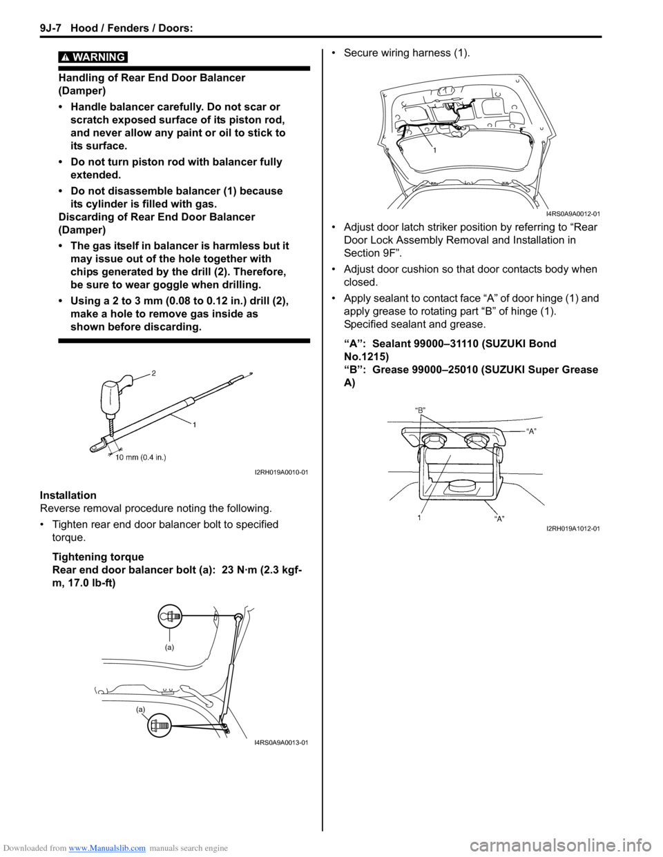
Handling of Rear End Door Balancer
(Damper)
• Handle balancer carefully. Do not scar or scratch exposed surface of its piston rod,
and never allow any paint or oil to stick to
its surface.
• Do not turn piston rod with balancer fully extended.
• Do not disassemble balancer (1) because its cylinder is filled with gas.
Discarding of Rear End Door Balancer
(Damper)
• The gas itself in balancer is harmless but it may issue out of the hole together with
chips generated by th e drill (2). Therefore,
be sure to wear goggle when drilling.
• Using a 2 to 3 mm (0.08 to 0.12 in.) drill (2),
make a hole to remove gas inside as
shown before discarding.
Installation
Reverse removal procedure noting the following.
• Tighten rear end door balancer bolt to specified torque.
Tightening torque
Rear end door balancer bolt (a): 23 N·m (2.3 kgf-
m, 17.0 lb-ft) • Secure wiring harness (1).
• Adjust door latch striker position by referring to “Rear
Door Lock Assembly Removal and Installation in
Section 9F”.
• Adjust door cushion so that door contacts body when closed.
• Apply sealant to contact face “A” of door hinge (1) and apply grease to rotating part “B” of hinge (1).
Specified sealant and grease.
“A”: Sealant 99000–31110 (SUZUKI Bond
No.1215)
“B”: Grease 99000–25010 (SUZUKI Super Grease
A)
I2RH019A0010-01
(a)
(a)
I4RS0A9A0013-01
1
I4RS0A9A0012-01
I2RH019A1012-01
Page 1377 of 1496
Downloaded from www.Manualslib.com manuals search engine Hood / Fenders / Doors: 9J-8
Specifications
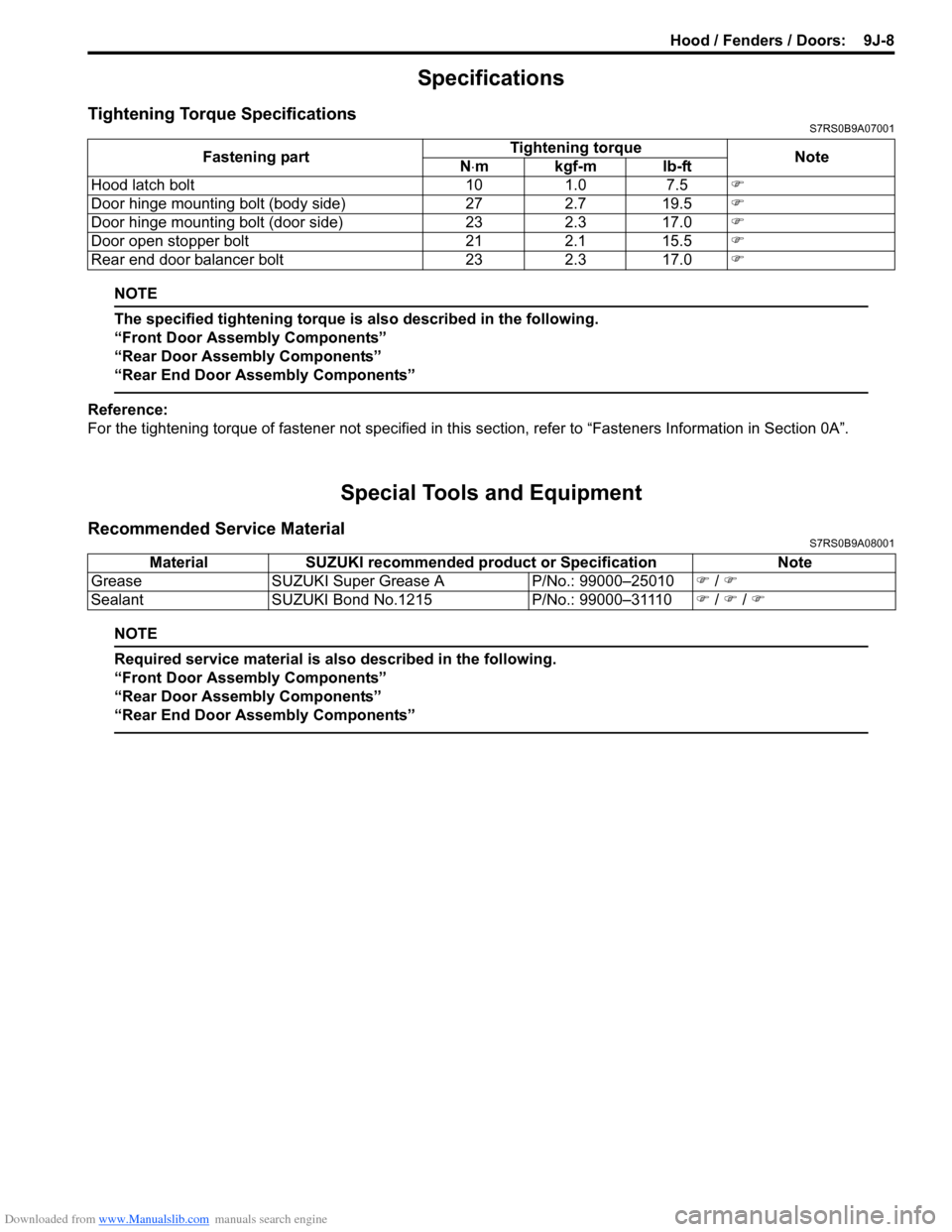
Tightening Torque SpecificationsS7RS0B9A07001
NOTE
The specified tightening torque is also described in the following.
“Front Door Assembly Components”
“Rear Door Assembly Components”
“Rear End Door Assembly Components”
Reference:
For the tightening torque of fastener not specified in this section, refer to “Fasteners Information in Section 0A”.
Special Tools and Equipment
Recommended Service MaterialS7RS0B9A08001
NOTE
Required service material is also described in the following.
“Front Door Assembly Components”
“Rear Door Assembly Components”
“Rear End Door Assembly Components”
Fastening part Tightening torque
Note
N ⋅mkgf-mlb-ft
Hood latch bolt 10 1.0 7.5 �)
Door hinge mounting bolt (body side) 27 2.7 19.5 �)
Door hinge mounting bolt (door side) 23 2.3 17.0 �)
Door open stopper bolt 21 2.1 15.5 �)
Rear end door balancer bolt 23 2.3 17.0 �)
MaterialSUZUKI recommended product or Specification Note
Grease SUZUKI Super Grease A P/No.: 99000–25010�) / �)
Sealant SUZUKI Bond No.1215 P/No.: 99000–31110�) / �) / �)
Page 1381 of 1496
Downloaded from www.Manualslib.com manuals search engine Body Structure: 9K-4
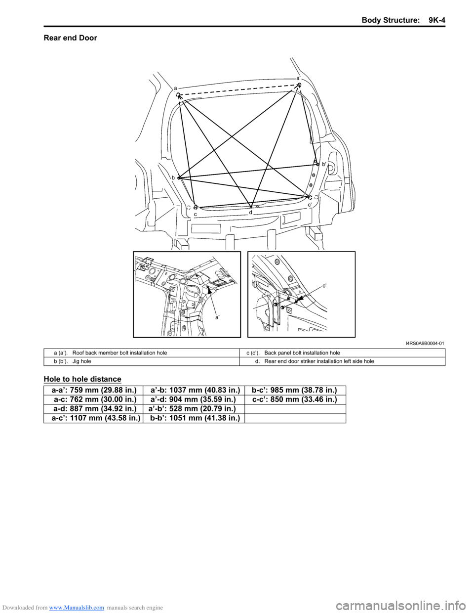
Rear end Door
Hole to hole distance
I4RS0A9B0004-01
a (a’). Roof back member bolt installation holec (c’). Back panel bolt installation hole
b (b’). Jig hole d. Rear end door striker installation left side hole
a-a’: 759 mm (29.88 in.) a’-b: 1037 mm (40.83 in.) b-c’: 985 mm (38.78 in.)
a-c: 762 mm (30.00 in.) a’-d: 904 mm (35.59 in.) c-c’: 850 mm (33.46 in.)
a-d: 887 mm (34.92 in.) a’-b’: 528 mm (20.79 in.)
a-c’: 1107 mm (43.58 in.) b-b’: 1051 mm (41.38 in.)
Page 1382 of 1496
Downloaded from www.Manualslib.com manuals search engine 9K-5 Body Structure:
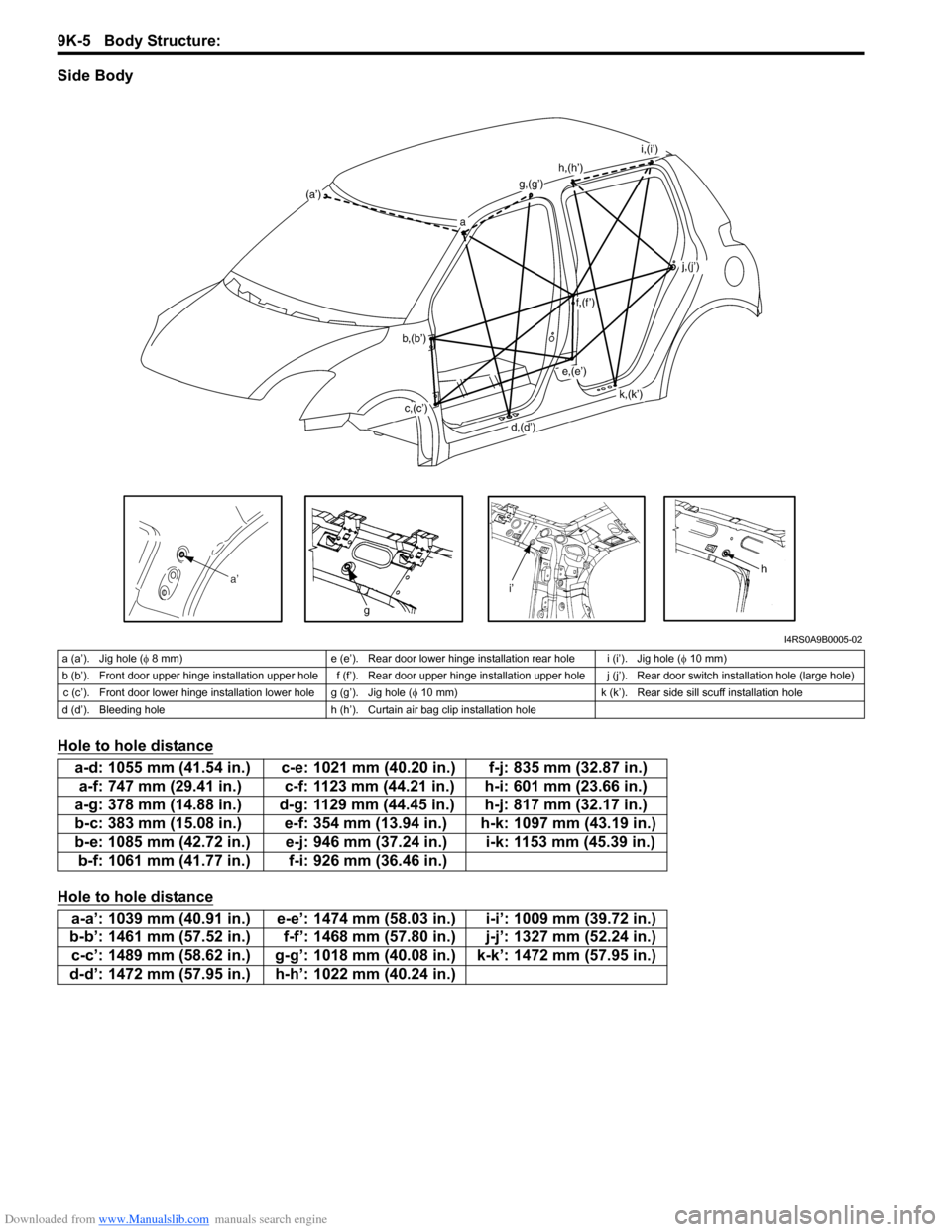
Side Body
Hole to hole distance
Hole to hole distance
I4RS0A9B0005-02
a (a’). Jig hole (φ 8 mm) e (e’). Rear door lower hinge installation rear hole i (i’). Jig hole ( φ 10 mm)
b (b’). Front door upper hinge installation upper hole f (f’). Rear door upper hinge installation upper hole j (j’). Rear door switc h installation hole (large hole)
c (c’). Front door lower hinge installation lower hole g (g’). Jig hole ( φ 10 mm) k (k’). Rear side sill scuff installation hole
d (d’). Bleeding hole h (h’). Curtain air bag clip installation hole
a-d: 1055 mm (41.54 in.) c-e: 1021 mm (40.20 in.) f-j: 835 mm (32.87 in.) a-f: 747 mm (29.41 in.) c-f: 1123 mm (44.21 in.) h-i: 601 mm (23.66 in.)
a-g: 378 mm (14.88 in.) d-g: 1129 mm (44.45 in.) h-j: 817 mm (32.17 in.)
b-c: 383 mm (15.08 in.) e-f: 354 mm (13.94 in.) h-k: 1097 mm (43.19 in.)
b-e: 1085 mm (42.72 in.) e-j: 946 mm (37.24 in.) i-k: 1153 mm (45.39 in.) b-f: 1061 mm (41.77 in.) f-i: 926 mm (36.46 in.)
a-a’: 1039 mm (40.91 in.) e-e’: 1474 mm (58.03 in.) i-i’: 1009 mm (39.72 in.)
b-b’: 1461 mm (57.52 in.) f-f’: 1468 mm (57.80 in.) j-j’: 1327 mm (52.24 in.) c-c’: 1489 mm (58.62 in.) g-g’: 1018 mm (40.08 in.) k-k’: 1472 mm (57.95 in.)
d-d’: 1472 mm (57.95 in.) h-h’: 1022 mm (40.24 in.)
Page 1388 of 1496
Downloaded from www.Manualslib.com manuals search engine 9L-1 Paint / Coatings:
Body, Cab and Accessories
Paint / Coatings
General Description
Anti-Corrosion Treatment ConstructionS7RS0B9C01001
WARNING!
Standard shop practices, particularly eye protection, should be followed during the performance of the
following operations to avoid personal injury.
As rust proof treatment, steel sheets are given corrosion resistance on the interior and/or exterior.
These corrosion resistance steel sheet materials ar e called one of two-side galvanized steel sheets.
It is for the sake of rust protection that these materials are selected and given a variety of treatments as described
blow.
• Steel sheets are treated with cathodic electro primer which is excellent in corrosion resistance.
• Rust proof wax coatings are applied to door and side sill insides where mois ture is liable to stay.
• Vinyl coating is applied to body underside and wheel housing inside.
• Sealer is applied to door hem, engine compartment steel sheet-to-steel sheet joint, and the like portions to prevent water penetration and resulting in rust occurrence.
In panel replacement or collision damage repair, leaving the relevant area untreated as it is in any operation which
does disturb the rust proof treatment will cause corrosion to th at area. Therefore, it is the essential function of any
repair operation to correctly recoat t he related surfaces of the relevant area.
All the metal panels are coated with metal conditioners an d primer coating during vehicle production. Following the
repair and/or replacement parts installation, every access ible bare metal surface should be cleaned and coated with
rust proof primer. Perform this operation prior to the application of sealer and rust proof wax coating.
Sealer is applied to the spec ific joints of a vehicle during production. The sealer is intended to prevent dust from
entering the vehicle and serves also as an anti corrosion barrier. The sealer is applied to the door and hood hem areas
and between panels. Correct and reseal the originally sealed joints if damaged. Reseal the attaching joints of a new
replacement panel and reseal the hem area of a replacement door or hood.
Use a quality sealer to seal the flanged joints, overlap joints and seams. The sealer must have flexible characteristics
and paint ability after it’s applied to repair areas.
For the sealer to fill open joints, use caulking material. Select a sealer in conf ormance with the place and purpose of a
specific use. Observe the ma nufacturer’s label-stand instructions when using the sealer.
In many cases, repaired places require color painting. When this is required, follow the ordinary techniques specified
for the finish preparation, color painting and undercoating build-up.
Rust proof wax, a penetrative compound, is applied to the metal-to-metal surfaces (door and side sill insides) where it
is difficult to use ordinary undercoating material for coating. Therefore, when selecting the rust proof wax, it may be the
penetrative type.
During the undercoating (vinyl coating) application, care should be taken that sealer is not applied to the engine-
related parts and shock absorber mounting or rotating parts. Following the under coating, make sure that body drain
holes are kept open.
The sequence of the application steps of the anti-corrosion materials are as follows:
1) Clean and prepare the metal surface.
2) Apply primer.
3) Apply sealer (all joints sealed originally).
4) Apply color in areas where color is required such as hem flanges, exposed joints and under body components.
5) Apply anti corrosion compound (penetrative wax).
6) Apply undercoating (rust proof material).
Page 1402 of 1496
Downloaded from www.Manualslib.com manuals search engine 10-ii Table of Contents
DTC P1615: ID Code Does Not Registered (Vehicle equipped with keyless start system
only) ................................................................10C-9
DTC P1616: Different Registration ID Codes (Vehicle equipped with keyless start system
only) ..............................................................10C-10
DTC P1618: CAN Communication Error (Reception Error for Keyless Start Control
Module) (Vehicle equipped with keyless
start system only) ..........................................10C-11
DTC P1621: Immobilizer Communication Line Error ......................................................10C-12
DTC P1622: EEPROM Reading / Writing Error ..............................................................10C-13
DTC P1623: Unregistered Transponder .........10C-13
DTC P1625: Immobilizer An tenna Error..........10C-14
DTC P1636: Immobilizer Information Registration Failure .......................................10C-14
DTC P1638: Immobilizer Information Mismatched ...................................................10C-15
Inspection of Immobilizer Control Module (ICM) and Its Circuit ....... ...............................10C-16
Repair Instructions ........... ...............................10C-18
Immobilizer Control Mo dule (ICM) Removal
and Installation ..............................................10C-18
Registration of the Ignition Key .......................10C-18
Procedure after ECM Replacement ................10C-18
Special Tools and Equipmen t .........................10C-19
Special Tool ....................................................10C-19
Keyless Start System ....... ......................10E-1
General Description ........................................... 10E-1
Keyless Start System Description ..................... 10E-1
Parts and Functions .......................................... 10E-2
Keyless Engine Start Function .......................... 10E-3
Door Lock Function of Keyless Start System .... 10E-4
Operation Area of Remote Controller................ 10E-5
Alarm Function .................................................. 10E-6
CAN Communication System Description......... 10E-6
Schematic and Routing Diagram ...................... 10E-7 Keyless Start System El ectric Wiring Circuit
Diagram .......................................................... 10E-7
Diagnostic Information and Procedures .......... 10E-8 Precautions in Diagnosing Troubles ................. 10E-8
Self-Diagnosis Function .................................... 10E-8
Keyless Start System Diagn osis Introduction ... 10E-8 Keyless Start System Chec
k ............................. 10E-8
Customer Questionnaire (E xample) .................. 10E-9
Key Indicator Lamp Check .............................. 10E-10
DTC Check...................................................... 10E-10
DTC Table ....................................................... 10E-11
DTC Clearance ............................................... 10E-12
Keyless Start System Symp tom Diagnosis ..... 10E-12
Keyless Start System Operation Inspection .... 10E-13
Door Lock Operation (Keyless Start System) . 10E-14
Inspection of Keyless Start Control Module and Its Circuits .............................................. 10E-14
No DTC Detection After Performing DTC Check ............................................................ 10E-18
Key Indicator Lamp Circuit Check (Key indicator lamp doesn’t light when ignition
knob switch is pushed.) ................................. 10E-20
Keyless Start Control Module Power and Ground Circuit Check .................................... 10E-22
DTC No. 11: Communi cation Error with
Steering Lock Unit ......................................... 10E-23
DTC No. 13 / No. 14: Release Signal Error from Steering Lock Unit / Steering Lock Unit
Malfunction .................................................... 10E-24
DTC No. 21 / No. 22: Internal Error of Keyless Start Control Module (EEPROM reading
error) / (EEPROM writing error) ............ ........ 10E-24
DTC No. 31: Lost Commun ication with BCM .. 10E-25
DTC No. 33: Control Module Communication
Bus Off .......................................................... 10E-27
DTC No. 51 / No. 52 / No. 53: Driver Side / Passenger Side / Rear End Door Request
Switch Failure................................................ 10E-28
Repair Instructions ............ .............................. 10E-30
Antennas and Request Switches Removal and Installation .............................................. 10E-30
Front Door (Driver and Passenger Side), Rear End Door Request Switch Inspection............ 10E-31
Steering Lock Unit Removal and Installation .. 10E-31
Steering Lock Unit Inspection ......................... 10E-31
Front Door Lock Switch In spection ................. 10E-31
Keyless Start Control Module Removal and Installation ..................................................... 10E-32
Remote Controller Inspection.......................... 10E-32
Replacement of Remote Controller Battery .... 10E-32
Registration Procedure for Remote Controller
ID Code ......................................................... 10E-33