2007 SUZUKI SWIFT body harness
[x] Cancel search: body harnessPage 1372 of 1496
Downloaded from www.Manualslib.com manuals search engine 9J-3 Hood / Fenders / Doors:
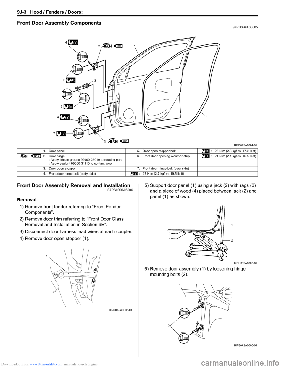
Front Door Assembly ComponentsS7RS0B9A06005
Front Door Assembly Removal and InstallationS7RS0B9A06006
Removal1) Remove front fender referring to “Front Fender Components”.
2) Remove door trim referring to “Front Door Glass Removal and Installa tion in Section 9E”.
3) Disconnect door harness lead wires at each coupler.
4) Remove door open stopper (1). 5) Support door panel (1) using a jack (2) with rags (3)
and a piece of wood (4) placed between jack (2) and
panel (1) as shown.
6) Remove door assembly (1) by loosening hinge mounting bolts (2).
2
21(a)4
(a)4
3(b)7
(b)7
(c)5
6
I4RS0A9A0004-01
1. Door panel 5. Door open stopper bolt: 23 N⋅m (2.3 kgf-m, 17.0 lb-ft)
2. Door hinge : Apply lithium grease 99000-25010 to rotating part.
: Apply sealant 99000-31110 to contact face. 6. Front door opening weather-strip
: 21 N⋅m (2.1 kgf-m, 15.5 lb-ft)
3. Door open stopper 7. Front door hinge bolt (door side)
4. Front door hinge bolt (body side) : 27 N⋅m (2.7 kgf-m, 19.5 lb-ft)
I4RS0A9A0005-01
I2RH019A0003-01
1
2
I4RS0A9A0006-01
Page 1376 of 1496
Downloaded from www.Manualslib.com manuals search engine 9J-7 Hood / Fenders / Doors:
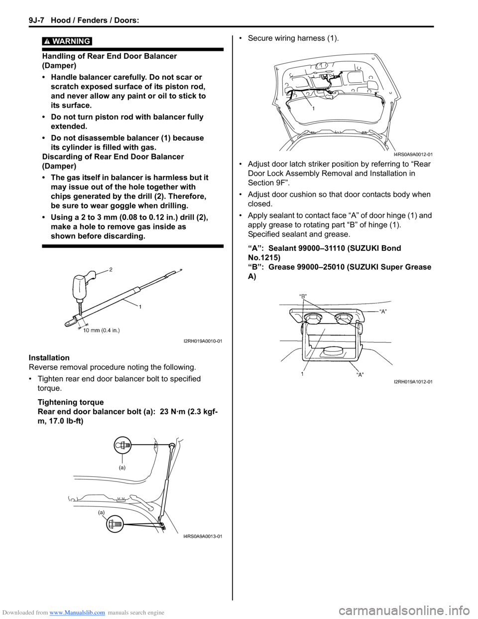
WARNING!
Handling of Rear End Door Balancer
(Damper)
• Handle balancer carefully. Do not scar or scratch exposed surface of its piston rod,
and never allow any paint or oil to stick to
its surface.
• Do not turn piston rod with balancer fully extended.
• Do not disassemble balancer (1) because its cylinder is filled with gas.
Discarding of Rear End Door Balancer
(Damper)
• The gas itself in balancer is harmless but it may issue out of the hole together with
chips generated by th e drill (2). Therefore,
be sure to wear goggle when drilling.
• Using a 2 to 3 mm (0.08 to 0.12 in.) drill (2),
make a hole to remove gas inside as
shown before discarding.
Installation
Reverse removal procedure noting the following.
• Tighten rear end door balancer bolt to specified torque.
Tightening torque
Rear end door balancer bolt (a): 23 N·m (2.3 kgf-
m, 17.0 lb-ft) • Secure wiring harness (1).
• Adjust door latch striker position by referring to “Rear
Door Lock Assembly Removal and Installation in
Section 9F”.
• Adjust door cushion so that door contacts body when closed.
• Apply sealant to contact face “A” of door hinge (1) and apply grease to rotating part “B” of hinge (1).
Specified sealant and grease.
“A”: Sealant 99000–31110 (SUZUKI Bond
No.1215)
“B”: Grease 99000–25010 (SUZUKI Super Grease
A)
I2RH019A0010-01
(a)
(a)
I4RS0A9A0013-01
1
I4RS0A9A0012-01
I2RH019A1012-01
Page 1410 of 1496
Downloaded from www.Manualslib.com manuals search engine 10B-7 Body Electrical Control System:
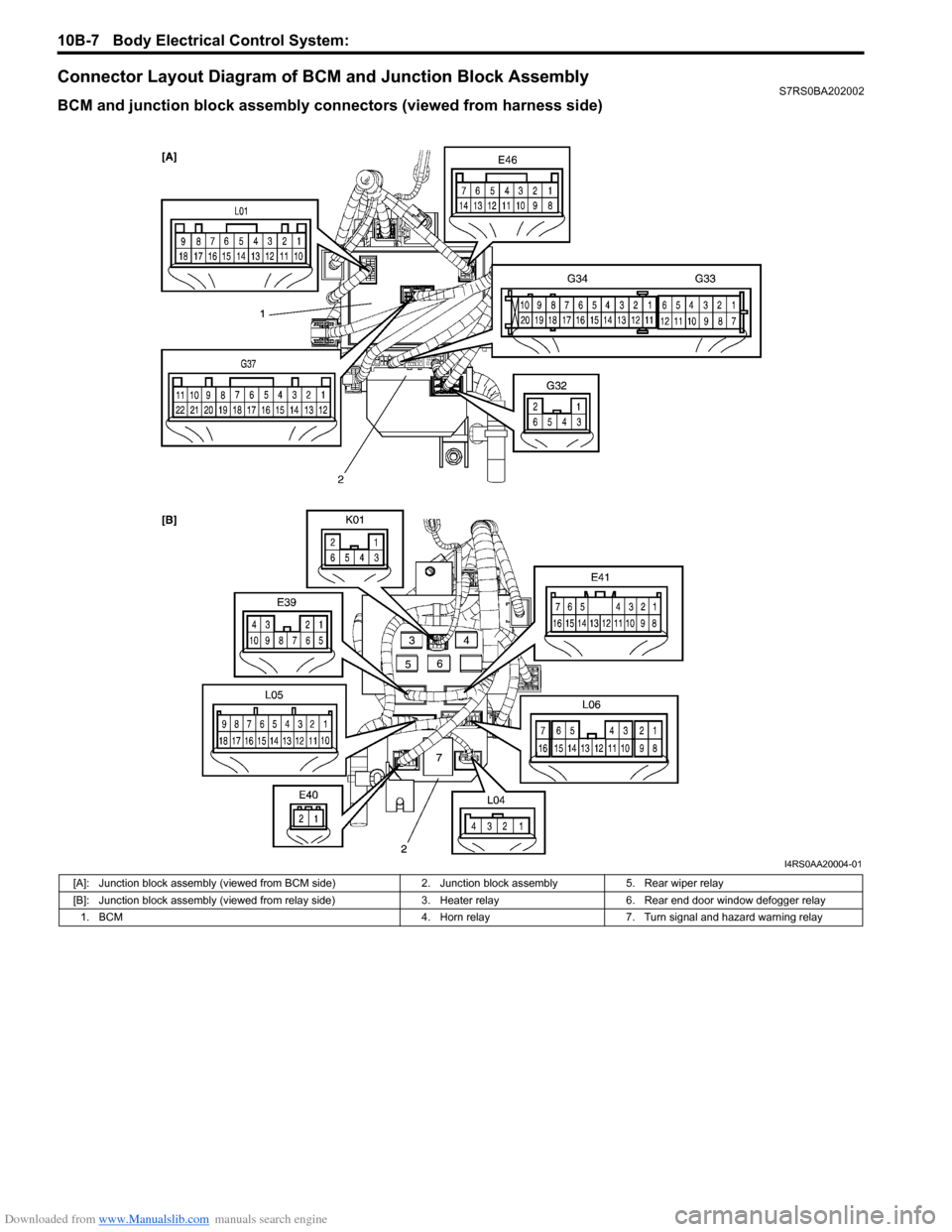
Connector Layout Diagram of BCM and Junction Block AssemblyS7RS0BA202002
BCM and junction block assembly connectors (viewed from harness side)
I4RS0AA20004-01
[A]: Junction block assembly (viewed from BCM side)2. Junction block assembly5. Rear wiper relay
[B]: Junction block assembly (viewed from relay side) 3.Heater relay 6. Rear end door window defogger relay
1. BCM 4. Horn relay7. Turn signal and hazard warning relay
Page 1414 of 1496
Downloaded from www.Manualslib.com manuals search engine 10B-11 Body Electrical Control System:
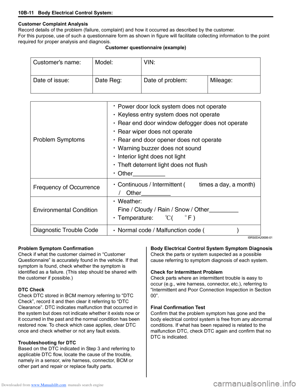
Customer Complaint Analysis
Record details of the problem (failure, complaint) and how it occurred as described by the customer.
For this purpose, use of such a questionnaire form as shown in figure will facilitate collectin g information to the point
required for proper analysis and diagnosis. Customer questionnaire (example)
Problem Symptom Confirmation
Check if what the custom er claimed in “Customer
Questionnaire” is accurately f ound in the vehicle. If that
symptom is found, check whether the symptom is
identified as a failure. (This step should be shared with
the customer if possible.)
DTC Check
Check DTC stored in BCM me mory referring to “DTC
Check”, record it and then clear it referring to “DTC
Clearance”. DTC indicates malfunction that occurred in
the system but does not indicate whether it exists now or
it occurred in the past and the normal condition has been
restored now. To check which case applies, clear DTC
once and check whether or not any fault exists.
Troubleshooting for DTC
Based on the DTC indicated in Step 3 and referring to
applicable DTC flow, locate the cause of the trouble,
namely in a sensor, wire harness, connector, BCM or
other part and repair or replace faulty parts. Body Electrical Control System Symptom Diagnosis
Check the parts or system
suspected as a possible
cause referring to symptom diagnosis of each system.
Check for Intermi ttent Problem
Check parts where an intermit tent trouble is easy to
occur (e.g., wire harness, connector, etc.), referring to
“Intermittent and Poor Connec tion Inspection in Section
00”.
Final Confirmation Test
Confirm that the problem symptom has gone and the
body electrical control system is free from any abnormal
conditions. If what has been repaired is related to the
malfunction DTC, check DTC again and confirm that no
DTC is indicated.
Customers name:
Model:
VIN:
Date of issue:
Date Reg:
Date of problem:
Mileage:
Problem Symptoms
Power door lock system does not operate
Keyless entry system does not operate
Rear end door window defogger does not operate
Rear wiper does not operate
Rear end door opener does not operate
Other
Frequency of Occurrence
Continuous / Intermittent ( times a day, a month)
/ Other
Environmental Condition
Weather:
Fine / Cloudy / Rain / Snow / Other
Temperature: (F )
Diagnostic Trouble Code Normal code / Malfunction code ( )
Warning buzzer does not sound
Interior light does not light
Theft deterrent light does not flush
I5RS0DA20006-01
Page 1419 of 1496
Downloaded from www.Manualslib.com manuals search engine Body Electrical Control System: 10B-16
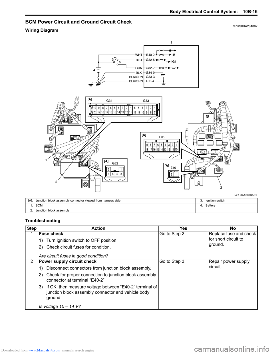
BCM Power Circuit and Ground Circuit CheckS7RS0BA204007
Wiring Diagram
Troubleshooting
I4RS0AA20008-01
[A]: Junction block assembly connector viewed from harness side3. Ignition switch
1. BCM 4. Battery
2. Junction block assembly
Step Action YesNo
1 Fuse check
1) Turn ignition switch to OFF position.
2) Check circuit fuses for condition.
Are circuit fuses in good condition? Go to Step 2.
Replace fuse and check
for short circuit to
ground.
2 Power supply circuit check
1) Disconnect connectors from junction block assembly.
2) Check for proper connection to junction block assembly
connector at terminal “E40-2”.
3) If OK, then measure voltage between “E40-2” terminal of junction block assembly connector and vehicle body
ground.
Is voltage 10 – 14 V? Go to Step 3.
Repair power supply
circuit.
Page 1421 of 1496
Downloaded from www.Manualslib.com manuals search engine Body Electrical Control System: 10B-18
DTC B1141 / DTC B1142 (No. 1141 / No. 1142): Outside Air Temperature (Ambient Temp.) Sensor
Circuit Malfunction
S7RS0BA204009
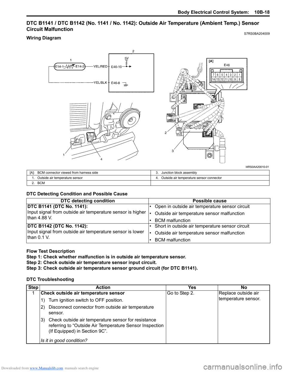
Wiring Diagram
DTC Detecting Condition and Possible Cause
Flow Test Description
Step 1: Check whether malfunction is in outside air temperature sensor.
Step 2: Check outside air temperature sensor input circuit.
Step 3: Check outside air temperature sensor ground circuit (for DTC B1141).
DTC Troubleshooting
I4RS0AA20010-01
[A]: BCM connector viewed from harness side 3. Junction block assembly
1. Outside air temperature sensor 4. Outside air temperature sensor connector
2. BCM
DTC detecting condition Possible cause
DTC B1141 (DTC No. 1141):
Input signal from outside air temperature sensor is higher
than 4.88 V. • Open in outside air temperature sensor circuit
• Outside air temperature sensor malfunction
• BCM malfunction
DTC B1142 (DTC No. 1142):
Input signal from outside air temperature sensor is lower
than 0.1 V. • Short in outside air temperature sensor circuit
• Outside air temperature sensor malfunction
• BCM malfunction
Step
Action YesNo
1 Check outside air temperature sensor
1) Turn ignition switch to OFF position.
2) Disconnect connector from outside air temperature
sensor.
3) Check outside air temperature sensor for resistance referring to “Outside Air Temperature Sensor Inspection
(If Equipped) in Section 9C”.
Is it in good condition? Go to Step 2.
Replace outside air
temperature sensor.
Page 1422 of 1496
Downloaded from www.Manualslib.com manuals search engine 10B-19 Body Electrical Control System:
DTC B1150 (No. 1150): Air Bag Communication Circuit MalfunctionS7RS0BA204010
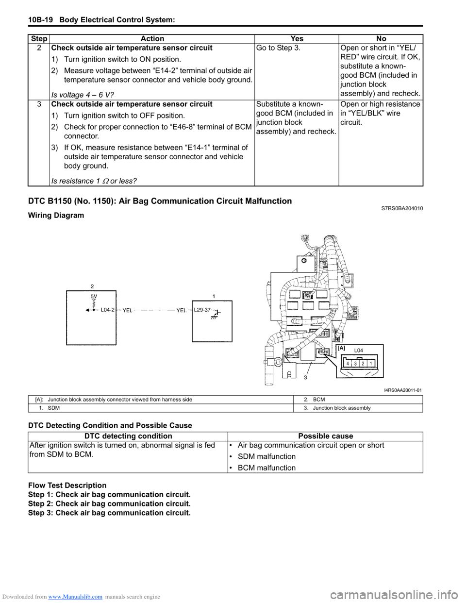
Wiring Diagram
DTC Detecting Condition and Possible Cause
Flow Test Description
Step 1: Check air bag communication circuit.
Step 2: Check air bag communication circuit.
Step 3: Check air bag communication circuit. 2
Check outside air temperature sensor circuit
1) Turn ignition switch to ON position.
2) Measure voltage between “E14-2” terminal of outside air
temperature sensor connector and vehicle body ground.
Is voltage 4 – 6 V? Go to Step 3. Open or short in “YEL/
RED” wire circuit. If OK,
substitute a known-
good BCM (included in
junction block
assembly) and recheck.
3 Check outside air temperature sensor circuit
1) Turn ignition switch to OFF position.
2) Check for proper connection to “E46-8” terminal of BCM
connector.
3) If OK, measure resistance between “E14-1” terminal of outside air temperature sens or connector and vehicle
body ground.
Is resistance 1
Ω or less? Substitute a known-
good BCM (included in
junction block
assembly) and recheck.
Open or high resistance
in “YEL/BLK” wire
circuit.
Step Action Yes No
I4RS0AA20011-01
[A]: Junction block assembly connect
or viewed from harness side 2. BCM
1. SDM 3. Junction block assembly
DTC detecting conditionPossible cause
After ignition switch is turned on, abnormal signal is fed
from SDM to BCM. • Air bag communication circuit open or short
• SDM malfunction
• BCM malfunction
Page 1424 of 1496
Downloaded from www.Manualslib.com manuals search engine 10B-21 Body Electrical Control System:
DTC B1170 (No. 1170): EEPROM Access ErrorS7RS0BA204012
DTC Detecting Condition and Possible Cause
DTC Troubleshooting
NOTE
Before performing steps below, be sure to perform “Body Electrical Control System Check”.
1) Ignition switch OFF.
2) Replace BCM.
3) Repeat BCM Check Flow Table.
DTC U0155 (No. 0155): Lost Communication with Instrument Panel Cluster (IPC) Control ModuleS7RS0BA204019
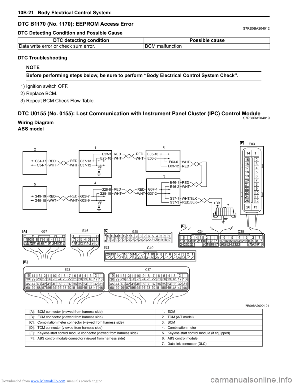
Wiring Diagram
ABS model DTC detecting condition Possible cause
Data write error or check sum error. BCM malfunction
REDWHTE03-6E03-12
6
3
7
REDWHT
1
[B]
[A]
G37E46
1234567
1234567
8910
11
8910
11
121314 121314
151617
18
19202122 [D]65
1615 141312 11 43
2423 2122 10 9 8 7
21
1920 1817
C3417 16
26 2515 14
65 3
42
13 12
23 2224 1110 9
212019 87
18
1
C35
[E]
REDWHTC37-13C37-12REDWHTC34-17C34-7
2
12345678910
11
141516
36 34 33 32 31 30 29 24 23
37
181920
[C] [F]
G49
E23-3E23-18
4
REDWHTG28-7G28-9REDWHTG49-19G49-18
5
REDWHTE03-10E03-8
G37-4G37-2
REDWHTE46-1E46-2REDWHTREDWHTG28-8G28-10
E03
15
16
17
18
19
20
21
22
23
24
25 2
3
4
5
6
7
8
9
10
11
12
1
13
14
26
E23C37
34
1819
567
1011
17
20
47 46
495051
2122
52 16
25 9
24
14
29
5557 54 53
59
60 58 2
262728
15
30
56 4832 31
34353637
4042 39 38
44
45 43 41 33 1
1213
238
34
1819
567
1011
17
20
47 46
495051
2122
52 16
25 9
24
14
29
5557 54 53
59
60 58 2
262728
15
30
56 4832 31
34353637
4042 39 38
44
45 43 41 331
1213
238
G281234567
8
910111213141516
1718
19
20
212223242526272829303132
RED/BLKWHT/BLKG37-3G37-1+BB
I7RS0BA20004-01
[A]: BCM connector (viewed from harness side) 1. ECM
[B]: ECM connector (viewed from harness side) 2. TCM (A/T model)
[C]: Combination meter connector (viewed from harness side) 3. BCM
[D]: TCM connector (viewed from harness side) 4. Combination meter
[E]: Keyless start control module connector (viewed from harness side) 5. Keyless start control module (if equipped)
[F]: ABS control module connector (viewed from harness side) 6. ABS control module
7. Data link connector (DLC)