2007 SUZUKI SWIFT special tools
[x] Cancel search: special toolsPage 935 of 1496
Downloaded from www.Manualslib.com manuals search engine Table of Contents 7-iii
Special Tools and Equipment ........................... 7B-79 Special Tool ...................................................... 7B-79
Page 949 of 1496
Downloaded from www.Manualslib.com manuals search engine Air Conditioning System: Manual Type 7B-1
HVAC
Air Conditioning System
Manual Type
Precautions
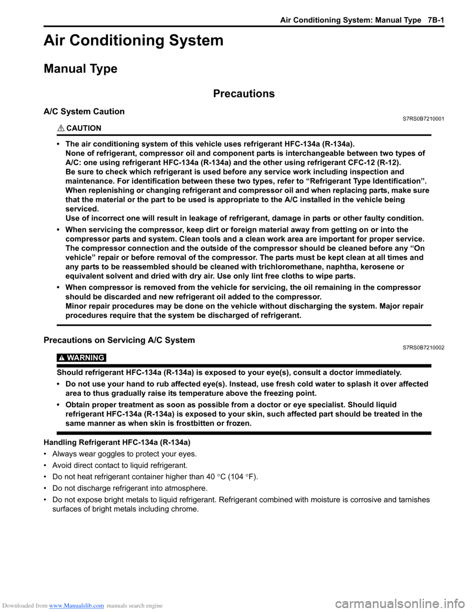
A/C System CautionS7RS0B7210001
CAUTION!
• The air conditioning system of this vehicle uses refrigerant HFC-134a (R-134a).
None of refrigerant, compressor oil and component parts is interchangeable between two types of
A/C: one using refrigerant HFC-134a (R-134a) and the other using refrigerant CFC-12 (R-12).
Be sure to check which refrigerant is used be fore any service work including inspection and
maintenance. For identification between these two types, refer to “Refrigerant Type Identification”.
When replenishing or changing refrigerant and comp ressor oil and when replacing parts, make sure
that the material or the part to be used is appropriate to the A/C installed in the vehicle being
serviced.
Use of incorrect one will result in leakage of refrigerant, damage in parts or other faulty condition.
• When servicing the compressor, keep dirt or foreign material away from getting on or into the compressor parts and system. Clean tools and a clean work area are important for proper service.
The compressor connection and the outside of the compressor should be cleaned before any “On
vehicle” repair or before removal of the compressor. The parts must be kept clean at all times and
any parts to be reassembled should be cleaned with trichloromethane, naphtha, kerosene or
equivalent solvent and dried with dry air. Use only lint free cloths to wipe parts.
• When compressor is removed from the vehicle for servicing, the oil remaining in the compressor
should be discarded and new refrigerant oil added to the compressor.
Minor repair procedures may be done on the vehicle without discharging the system. Major repair
procedures require that the system be discharged of refrigerant.
Precautions on Servicing A/C SystemS7RS0B7210002
WARNING!
Should refrigerant HFC-134a (R-134a) is exposed to your eye(s), consult a doctor immediately.
• Do not use your hand to rub affected eye(s). Instead, use fresh cold water to splash it over affected area to thus gradually raise its temperature above the freezing point.
• Obtain proper treatment as soon as possible from a doctor or eye specialist. Should liquid refrigerant HFC-134a (R-134a) is exposed to your skin, such affected part should be treated in the
same manner as when skin is frostbitten or frozen.
Handling Refrigerant HFC-134a (R-134a)
• Always wear goggles to protect your eyes.
• Avoid direct contact to liquid refrigerant.
• Do not heat refrigerant container higher than 40 °C (104 ° F).
• Do not discharge refrigerant into atmosphere.
• Do not expose bright metals to liquid refrigerant. Refrig erant combined with moisture is corrosive and tarnishes
surfaces of bright metals including chrome.
Page 981 of 1496

Downloaded from www.Manualslib.com manuals search engine Air Conditioning System: Manual Type 7B-33
Special Tools and Equipment
Recommended Service MaterialS7RS0B7218001
NOTE
Required service material is also described in the following.
“Precautions on Servicing A/C System”
Special ToolS7RS0B7218002
Material SUZUKI recommended product or Specification Note
Compressor oil MATSUSHITADEN KI GU10 P/No.: 99000–99015–
00A �)
/ �)
Silicon sealant SUZUKI SILICON SEALANT KE-
347W (100g) P/No.: 99000–34220
�)
09900–06107 09990–86012
Snap ring pliers (opening
type) Gas leak detector
�) / �) / �) / �) This kit includes following
items. 1. Gas leak detector,
2. Instruction manual, 3.
Filter, 4. Sensor, 5. Dri-sell
battery (size D)�) / �)
09991–06310
Armature plate holder
�) / �)
1 2
3 4
5
Page 1027 of 1496
Downloaded from www.Manualslib.com manuals search engine Air Conditioning System: Automatic Type 7B-79
Compressor Drive Belt Removal and
Installation
S7RS0B7226032
Refer to “Compressor Drive Belt Removal and
Installation”.
Compressor Assembly Removal and
Installation
S7RS0B7226033
Refer to “Compressor Assembly Removal and
Installation”.
Compressor Assembly ComponentsS7RS0B7226034
Refer to “Compressor Assembly Components”.
Magnet Clutch Removal and InstallationS7RS0B7226035
Refer to “Magnet Clutch Removal and Installation”.
Magnet Clutch InspectionS7RS0B7226036
Refer to “Magnet Clutch Inspection”.
Relief Valve InspectionS7RS0B7226039
Refer to “Relief Valve Inspection”.
Special Tools and Equipment
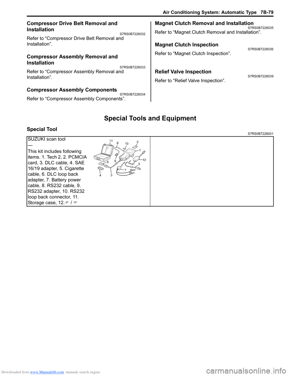
Special ToolS7RS0B7228001
SUZUKI scan tool
—
This kit includes following
items. 1. Tech 2, 2. PCMCIA
card, 3. DLC cable, 4. SAE
16/19 adapter, 5. Cigarette
cable, 6. DLC loop back
adapter, 7. Battery power
cable, 8. RS232 cable, 9.
RS232 adapter, 10. RS232
loop back connector, 11.
Storage case, 12.�) / �)
Page 1030 of 1496
Downloaded from www.Manualslib.com manuals search engine 8-ii Table of Contents
DTC B1062 / B1066: Driver / Passenger Side-Air Bag Initiator Circuit Resistance Low .......... 8B-67
DTC B1063 / B1067: Driver / Passenger Side- Air Bag Initiator Circuit S hort to Ground .......... 8B-70
DTC B1064 / B1068: Driver / Passenger Side- Air Bag Initiator Circu it Short to Power
Circuit .............................................................. 8B-73
DTC B1071: Forward-Sensor Performance Problem ........................................................... 8B-76
DTC B1072: Forward-Sensor Communication Error ................................................................ 8B-76
DTC B1073: Forward-Sensor Circuit Short to Ground ............................................................ 8B-76
DTC B1074: Forward-Sensor Circuit Short to Power Circuit or Open ..................................... 8B-78
DTC B1081 / B1091: Driver / Passenger Side- Sensor Performance Probl em ......................... 8B-80
DTC B1082 / B1092: Driver / Passenger Side- Sensor Communication Erro r .......................... 8B-80
DTC B1083 / B1093: Driver / Passenger Side- Sensor Circuit Short to Ground ....................... 8B-80
DTC B1084 / B1094: Driver / Passenger Side- Sensor Circuit Short to Power Circuit or
Open ............................................................... 8B-81
DTC B1085 / B1095: Wrong Side-Sensor (Driver Side / Passenger) ID ........................... 8B-83
DTC B1361 / B1365: Driver / Passenger Side Curtain-Air Bag Initiator Circuit Resistance
High ................................................................. 8B-84
DTC B1362 / B1366: Driver / Passenger Side Curtain-Air Bag Initiator Circuit Resistance
Low ................................................................. 8B-86
DTC B1363 / B1367: Driver / Passenger Side Curtain-Air Bag Initiator Circuit Short to
Ground ............................................................ 8B-88
DTC B1364 / B1368: Driver / Passenger Side Curtain-Air Bag Initiator Circuit Short to
Power Circuit ................................................... 8B-90
Contact Coil Cable and Its Circuit Check .......... 8B-93 Inspection of Intermittent and Poor
Connections .................................................... 8B-95
Repair and Inspection Required after Accident .......................................................... 8B-96
Repair Instructions ............ ................................8B-98
Disabling Air Bag System.................................. 8B-98
Enabling Air Bag System .................................. 8B-99
SDM Removal and Installation ........................ 8B-100
SDM Inspection ............................................... 8B-101
Driver Air Bag (Inflato r) Module Removal and
Installation ..................................................... 8B-101
Driver Air Bag (Inflator) Module Inspection ..... 8B-103
Passenger Air Bag (Inflator) Module Removal and Installation .............................................. 8B-103
Passenger Air Bag (I nflator) Module
Inspection ...................................................... 8B-105
Side-Air Bag (Inflator) Module Removal and
Installation ..................................................... 8B-105
Side-Air Bag (Inflator) Inspection .................... 8B-107
Side Curtain-Air Bag (Inflator) Module Removal and Installation ............................... 8B-107
Side Curtain-Air Bag (Inflator) Module Inspection ...................................................... 8B-109
Forward-Sensor Removal and Installation ...... 8B-109
Forward-Sensor In spection ............................. 8B-110
Side-Sensor Removal and Installation ............ 8B-110
Side-Sensor Inspection ................................... 8B-111
Passenger Air Bag (Inflator) Module Repair
Harness Installation....................................... 8B-112
Air Bag (Inflator) Module and Seat Belt Pretensioner Disposal ................................... 8B-113
Deployed Air Bag (Inflator) Module and Activated Seat Belt Pretensioner Disposal.... 8B-124
Specifications .................. .................................8B-125
Tightening Torque Specifications .................... 8B-125
Special Tools and Equipmen t .........................8B-125
Use of Special Tools ....................................... 8B-125
Recommended Service Material ..................... 8B-127
Special Tool .................................................... 8B-127
Page 1063 of 1496
Downloaded from www.Manualslib.com manuals search engine Air Bag System: 8B-25
DTC Will Set when
The combined resistance of the driver air bag (inflator) module, contact coil assembly, harness wiring and connector
terminal contact is above a spec ified value for specified time.
Flow Test Description
Step 1: Check whether malfunction is in contact coil and driver air bag (inflator) module or the others.
Step 2: Check driver air bag (inflator) module initiator circuit. (in instrument panel and floor harness)
Step 3: Check driver air bag (inflator) module initiator circuit. (in floor harness)
Step 4: Check whether malfunction is in contact coil or driver air bag (inflator) module.
DTC Troubleshooting
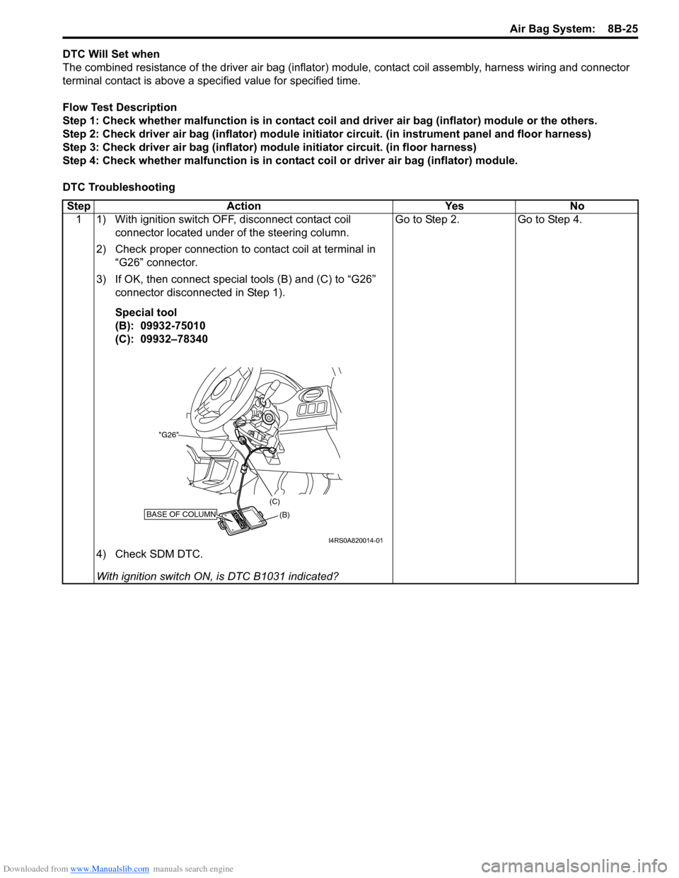
Step Action Yes No 1 1) With ignition switch OFF, disconnect contact coil connector located under of the steering column.
2) Check proper connection to contact coil at terminal in “G26” connector.
3) If OK, then connect special tools (B) and (C) to “G26” connector disconnected in Step 1).
Special tool
(B): 09932-75010
(C): 09932–78340
4) Check SDM DTC.
With ignition switch ON , is DTC B1031 indicated? Go to Step 2. Go to Step 4.
BASE OF COLUMN(B)
(C)
"G26"
I4RS0A820014-01
Page 1064 of 1496
Downloaded from www.Manualslib.com manuals search engine 8B-26 Air Bag System:
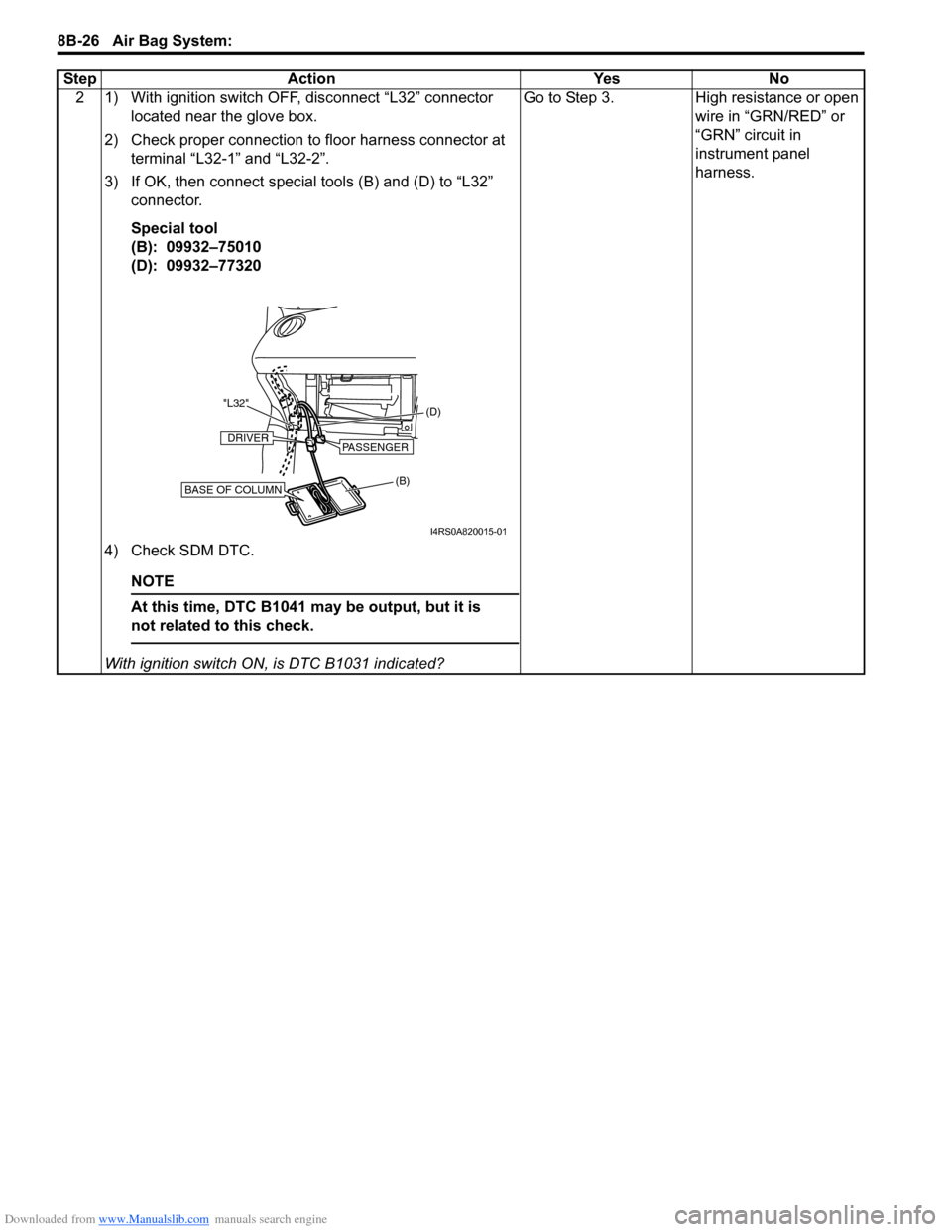
2 1) With ignition switch OFF, disconnect “L32” connector located near the glove box.
2) Check proper connection to floor harness connector at terminal “L32-1” and “L32-2”.
3) If OK, then connect special tools (B) and (D) to “L32” connector.
Special tool
(B): 09932–75010
(D): 09932–77320
4) Check SDM DTC.
NOTE
At this time, DTC B1041 ma y be output, but it is
not related to this check.
With ignition switch ON , is DTC B1031 indicated? Go to Step 3. High resistance or open
wire in “GRN/RED” or
“GRN” circuit in
instrument panel
harness.
Step Action Yes No
(B) (D)
"L32"BASE OF COLUMN
DRIVERPASSENGER
I4RS0A820015-01
Page 1065 of 1496
Downloaded from www.Manualslib.com manuals search engine Air Bag System: 8B-27
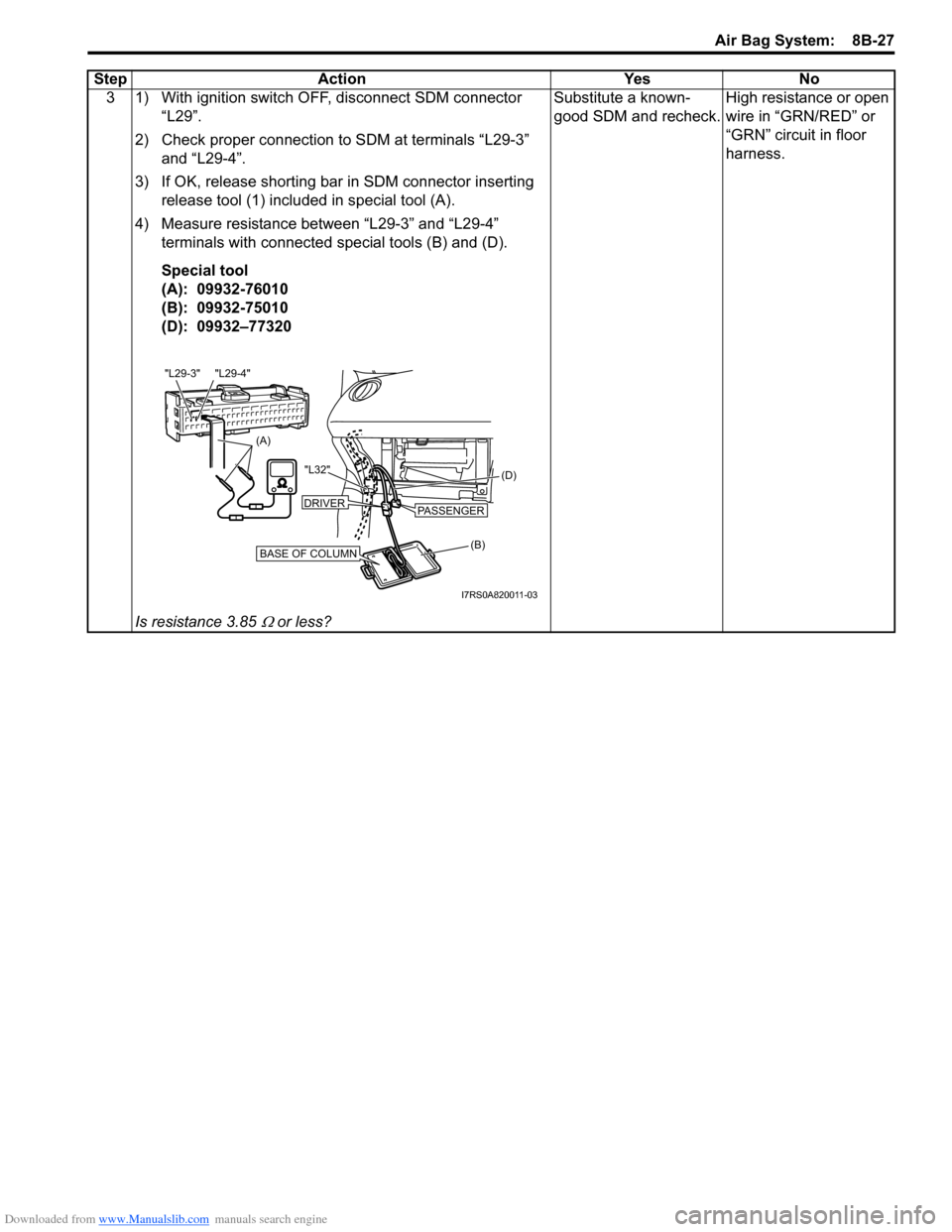
3 1) With ignition switch OFF, disconnect SDM connector “L29”.
2) Check proper connection to SDM at terminals “L29-3” and “L29-4”.
3) If OK, release shorting bar in SDM connector inserting
release tool (1) included in special tool (A).
4) Measure resistance between “L29-3” and “L29-4” terminals with connected special tools (B) and (D).
Special tool
(A): 09932-76010
(B): 09932-75010
(D): 09932–77320
Is resistance 3.85
Ω or less? Substitute a known-
good SDM and recheck.
High resistance or open
wire in “GRN/RED” or
“GRN” circuit in floor
harness.
Step Action Yes No
(A)
"L29-4"
"L29-3"
(B) (D)
"L32"BASE OF COLUMN
DRIVERPASSENGER
I7RS0A820011-03