2007 SUZUKI SWIFT Fi fuse
[x] Cancel search: Fi fusePage 612 of 1496
Downloaded from www.Manualslib.com manuals search engine 4F-38 Electronic Stability Program:
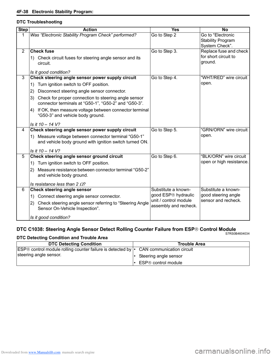
DTC Troubleshooting
DTC C1038: Steering Angle Sensor Detect Rolling Counter Failure from ESP® Control ModuleS7RS0B4604034
DTC Detecting Condition and Trouble AreaStep Action Yes No
1 Was “Electronic Stability Pr ogram Check” performed? Go to Step 2 Go to “Electronic
Stability Program
System Check”.
2 Check fuse
1) Check circuit fuses for steering angle sensor and its
circuit.
Is it good condition? Go to Step 3. Replace fuse and check
for short circuit to
ground.
3 Check steering angle sensor power supply circuit
1) Turn ignition switch to OFF position.
2) Disconnect steering angle sensor connector.
3) Check for proper connection to steering angle sensor
connector terminals at “G50-1”, “G50-2” and “G50-3”.
4) If OK, then measure voltage between connector terminal “G50-3” and vehicle body ground.
Is it 10 – 14 V? Go to Step 4. “WHT/RED” wire circuit
open.
4 Check steering angle sensor power supply circuit
1) Measure voltage between connector terminal “G50-1”
and vehicle body ground with ignition switch turned ON.
Is it 10 – 14 V? Go to Step 5. “GRN/ORN” wire circuit
open.
5 Check steering angle sensor ground circuit
1) Turn ignition switch to OFF position.
2) Measure resistance between connector terminal “G50-2”
and vehicle body ground.
Is resistance less than 2
Ω? Go to Step 6. “BLK/ORN” wire circuit
open or high resistance.
6 Check steering angle sensor
1) Connect steering angle sensor connector.
2) Check steering angle sensor referring to “Steering Angle
Sensor On-Vehicle Inspection”.
Is it good condition? Substitute a known-
good ESP
® hydraulic
unit / control module
assembly and recheck. Substitute a known-
good steering angle
sensor and recheck.
DTC Detecting Condition
Trouble Area
ESP ® control module rolling counte r failure is detected by
steering angle sensor. • CAN communication circuit
• Steering angle sensor
• ESP
® control module
Page 614 of 1496
Downloaded from www.Manualslib.com manuals search engine 4F-40 Electronic Stability Program:
DTC C1041 / C1042 / C1043 / C1044 / C1045 / C1046 / C1051 / C1052 / C1053 / C1054 / C1055 / C1056:
Solenoid Circuit Failure
S7RS0B4604052
DTC C1041 / C1045 / C1051 / C1055: Right-Front / Left-Front / Right-Rear / Left-Rear Inlet Solenoid
Circuit Failure
DTC C1042 / C1046 / C1052 / C1056: Right-Front / Left-Front / Right-Rear / Left-Rear Outlet Solenoid
Circuit Failure
DTC C1043 / C1044: Master Cylinder Cut Solenoid Circuit No. 1 / No. 2 Failure
DTC C1053 / C1054: Low Pressure Solenoid Circuit No. 1 / No. 2 Failure
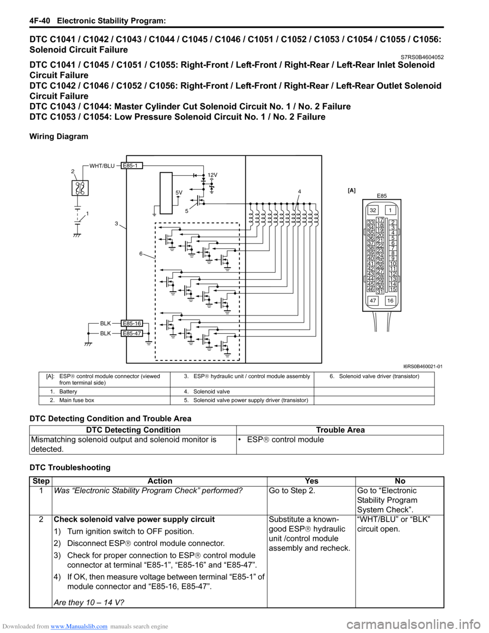
Wiring Diagram
DTC Detecting Condition and Trouble Area
DTC Troubleshooting
[A]E85
161
15
2
3
4
5
6
7
8
9
10
11
12
13
14
17
18
19
20
21
22
23
24
25
26
27
28
29
30
31
3233
34
35
36
37
38
39
40
41
42
43
44
45
46
47
WHT/BLU
1
2
54
BLK
BLK
5V
12V
E85-1
E85-16
E85-47
6
3
I6RS0B460021-01
[A]: ESP
® control module connector (viewed
from terminal side) 3. ESP
® hydraulic unit / control module assemb ly 6. Solenoid valve driver (transistor)
1. Battery 4. Solenoid valve
2. Main fuse box 5. Solenoid valve power supply driver (transistor)
DTC Detecting Condition Trouble Area
Mismatching solenoid output and solenoid monitor is
detected. • ESP
® control module
Step Action YesNo
1 Was “Electronic Stability Pr ogram Check” performed? Go to Step 2.Go to “Electronic
Stability Program
System Check”.
2 Check solenoid valve power supply circuit
1) Turn ignition switch to OFF position.
2) Disconnect ESP ® control module connector.
3) Check for proper connection to ESP ® control module
connector at terminal “E85-1”, “E85-16” and “E85-47”.
4) If OK, then measure voltage between terminal “E85-1” of module connector and “E85-16, E85-47”.
Are they 10 – 14 V? Substitute a known-
good ESP
® hydraulic
unit /control module
assembly and recheck. “WHT/BLU” or “BLK”
circuit open.
Page 615 of 1496
Downloaded from www.Manualslib.com manuals search engine Electronic Stability Program: 4F-41
DTC C1057: ESP® Control Module Power Supply Circuit FailureS7RS0B4604053
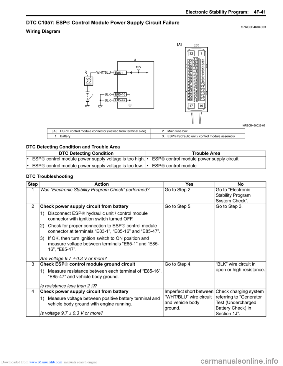
Wiring Diagram
DTC Detecting Condition and Trouble Area
DTC Troubleshooting
[A]
E85
161
15
2
3
4
5
6
7
8
9
10
11
12
13
14
17
18
19
20
21
22
23
24
25
26
27
28
29
30
31
3233
34
35
36
37
38
39
40
41
42
43
44
45
46
47
WHT/BLU
1
2
3
12V
E85-1
BLKE85-16
E85-47BLK
I6RS0B460023-02
[A]: ESP
® control module connector (viewed from terminal side) 2. Main fuse box
1. Battery 3. ESP ® hydraulic unit / control module assembly
DTC Detecting Condition Trouble Area
• ESP ® control module power supply voltage is too high.
• ESP ® control module power supply voltage is too low. • ESP
® control module power supply circuit
• ESP ® control module
Step Action YesNo
1 Was “Electronic Stability Pr ogram Check” performed? Go to Step 2.Go to “Electronic
Stability Program
System Check”.
2 Check power supply circuit from battery
1) Disconnect ESP ® hydraulic unit / control module
connector with ignition switch turned OFF.
2) Check for proper connection to ESP ® control module
connector at terminals “E83-1”, “E85-16” and “E85-47”.
3) If OK, then turn ignition switch to ON position and measure voltage between terminals “E85-1” and “E85-
16”, “E85-47”.
Are voltage 9.7
± 0.3 V or more? Go to Step 5. Go to Step 3.
3 Check ESP ® control module ground circuit
1) Measure resistance between each terminal of “E85-16”, “E85-47” and vehicle body ground.
Is resistance less than 2
Ω? Go to Step 4. “BLK” wire circuit in
open or high resistance.
4 Check power supply circuit from battery
1) Measure voltage between positive battery terminal and
vehicle body ground with engine running.
Is voltage 9.7
± 0.3 V or more? Imperfect short between
“WHT/BLU” wire circuit
and vehicle body
ground.
Check charging system
referring to “Generator
Test (Undercharged
Battery Check) in
Section 1J”.
Page 616 of 1496
Downloaded from www.Manualslib.com manuals search engine 4F-42 Electronic Stability Program:
DTC C1061: Pump Motor and/or Motor Driver Circuit FailureS7RS0B4604054
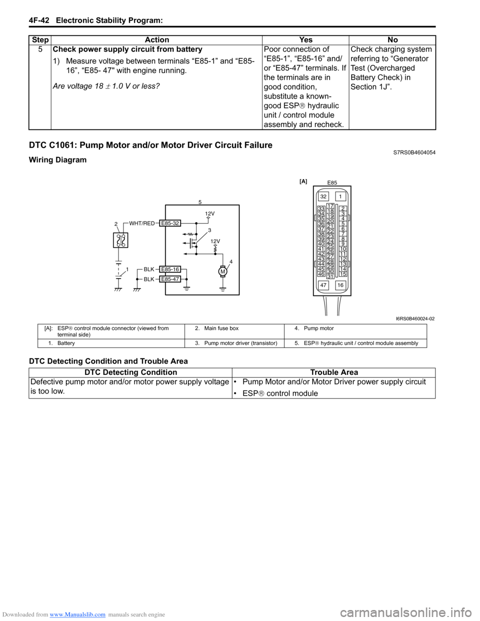
Wiring Diagram
DTC Detecting Condition and Trouble Area5
Check power supply circuit from battery
1) Measure voltage between terminals “E85-1” and “E85-
16”, “E85- 47" with engine running.
Are voltage 18
± 1.0 V or less? Poor connection of
“E85-1”, “E85-16” and/
or “E85-47” terminals. If
the terminals are in
good condition,
substitute a known-
good ESP
® hydraulic
unit / control module
assembly and recheck. Check charging system
referring to “Generator
Test (Overcharged
Battery Check) in
Section 1J”.
Step Action Yes No
[A]
E85
161
15
2
3
4
5
6
7
8
9
10
11
12
13
14
17
18
19
20
21
22
23
24
25
26
27
28
29
30
31
3233
34
35
36
37
38
39
40
41
42
43
44
45
46
47
4
51
2
WHT/RED3
12V
M
12V
BLK
BLK
E85-16
E85-47
E85-32
I6RS0B460024-02
[A]: ESP
® control module connector (viewed from
terminal side) 2. Main fuse box 4. Pump motor
1. Battery 3. Pump motor driver (transistor) 5. ESP® hydraulic unit / control module assembly
DTC Detecting ConditionTrouble Area
Defective pump motor and/or motor power supply voltage
is too low. • Pump Motor and/or Motor Driver power supply circuit
• ESP
® control module
Page 617 of 1496

Downloaded from www.Manualslib.com manuals search engine Electronic Stability Program: 4F-43
DTC Troubleshooting
DTC C1063: Solenoid Valve Power Supply Driver Circuit FailureS7RS0B4604055
Wiring Diagram
DTC Detecting Condition and Trouble AreaStep Action Yes No
1 Was “Electronic Stability Pr ogram Check” performed? Go to Step 2. Go to “Electronic
Stability Program
System Check”.
2 Check ESP ® control module power supply circuit
1) Turn Ignition switch to OFF position.
2) Disconnect ESP ® control module connector.
3) Check for proper connection to ESP ® control module
connector at terminal “E85-32”.
4) If OK, then measure voltage between terminal “E85-32” of module connector and body ground.
Is it 10 – 14 V? Go to Step 3. “WHT/RED” circuit
open.
3 Check ESP ® control module ground circuit
1) Measure resistance between terminal “E85-16” and “E85-47” ESP ® control module connector and vehicle
body ground.
Are resistance less than 1
Ω? Substitute a known-
good ESP
® hydraulic
unit / control module
assembly and recheck. Ground circuit for ESP
®
control module open or
high resistance.
3 4 12V
GRN/ORNGRN
7
5V12V
WHTE85-35
E85-1WHT/BLU5
6
8
1
2
[A]
E85
161
15
2
3
4
5
6
7
8
9
10
11
12
13
14
17
18
19
20
21
22
23
24
25
26
27
28
29
30
31
3233
34
35
36
37
38
39
40
41
42
43
44
45
46
47
I6RS0B460025-02
[A]: ESP ® control module connector (viewed from
terminal side) 3. Ignition switch 6. Power control unit
1. Battery 4. Junction block assembly 7. Solenoid valve power supply driver (transistor)
2. Main fuse box 5. ESP® hydraulic unit / control
module assembly 8. To solenoid valve
DTC Detecting Condition
Trouble Area
• Mismatching solenoid output and solenoid monitor is detected.
• Solenoid valve circuit is shorted to power or ground circuit in ESP ® control module • Solenoid valve power supply circuit
• ESP
® control module
Page 618 of 1496

Downloaded from www.Manualslib.com manuals search engine 4F-44 Electronic Stability Program:
DTC Troubleshooting
DTC 1071: ESP® Control Module Internal DefectS7RS0B4604056
DTC Detecting Condition and Trouble Area
DTC Troubleshooting
1) Turn ignition switch to OFF position.
2) Check for proper connection from harness to ESP ® control module.
3) If OK, substitute an ESP ® hydraulic unit / control module assembly with correct part number.
4) Recheck system.
Step
Action YesNo
1 Was “Electronic Stability Pr ogram Check” performed? Go to Step 2.Go to “Electronic
Stability Program
System Check”.
2 Check power supply circuit from battery
1) Check battery voltage.
Is it about 11 V or higher? Go to Step 3.
Check charging system
referring to “Battery
Inspection in Section
1J” and “Generator Test
(Undercharged Battery
Check) in Section 1J”.
3 Check fuse
1) Check main fuse for solenoid and its terminal.
Is it in good condition? Go to Step 4.
Replace fuse and check
for short circuit to
ground.
4 Check solenoid valve power supply circuit
1) Turn ignition switch to OFF position.
2) Disconnect control module connector.
3) Check for proper connection to ESP® control module at
terminal “E85-1”.
4) If OK, then measure voltage between connector terminal “E85-1” and vehicle body ground.
Is it 10 – 14 V? Substitute a known-
good ESP
® hydraulic
unit / control module
assembly and recheck. “WHT/BLU” circuit
imperfect short to
ground.
DTC Detecting Condition
Trouble Area
ESP ® control module internal defect is detected. • ESP ® control module
Page 628 of 1496

Downloaded from www.Manualslib.com manuals search engine 4F-54 Electronic Stability Program:
Repair Instructions
ESP® Hydraulic Unit Operation CheckS7RS0B4606025
1) Check that basic brake system other than ESP ® is
in good condition.
2) Check that battery voltage is 11 V or higher.
3) Lift up vehicle.
4) Set transmission to neutral and release parking brake.
5) Turn each wheel gradually by hand to check if braked ragging occurs. If it does, correct.
6) Connect SUZUKI scan tool to data link connector (DLC) (1) with ignition switch OFF.
Special tool
(A): SUZUKI scan tool
7) Turn ignition switch to ON position and select menu press / depress in “HYDRAULIC CONTROL TEST”
under “miscellaneous test” (“MISC. TEST”) mode of
SUZUKI scan tool.
Refer to SUZUKI scan tool operator’s manual for
further details.
8) Perform the following checks with help of another person.
• Depressurization checkStep on brake pedal (1) and then select testing
wheel by SUZUKI scan tool and the wheel (2)
should be turned by another person’s hand. At this
time, check whether the wheel rotates freely due
to brake depressurization. • Pressurization check
Step off brake pedal (1) and then select testing
wheel by SUZUKI scan tool and the wheel (2)
should be turned by another person’s hand. At this
time, check whether the wheel locks due to brake
pressurization.
NOTE
Pressurization / Depressurization by SUZUKI
scan tool is available for 0.5 second.
9) Check for all 4-wheels condition respectively. If a faulty condition is found, replace hydraulic unit /
control module assembly.
10) After completing the check, turn ignition switch to OFF position and disconnect SUZUKI scan tool from
DLC.
Sensor CalibrationS7RS0B4606015
CAUTION!
If any DTC(s) other than C1075, C1076 or
C1078 are detected, sensor calibration can
not be completed. Repair the detected DTC
first.
NOTE
Steering angle sensor calibration is needed
when battery, “DOME” fuse or the steering
angle sensor is removed.
This sensor calibration can be done with/
without SUZUKI Scan Tool.
When ESP ® control module and/or yaw rate /
G sensor assembly is removed, sensor
calibration is needed with SUZUKI Scan Tool.
(A)
1
I4RS0B450003-01
I4RH01450021-01
Page 629 of 1496
Downloaded from www.Manualslib.com manuals search engine Electronic Stability Program: 4F-55
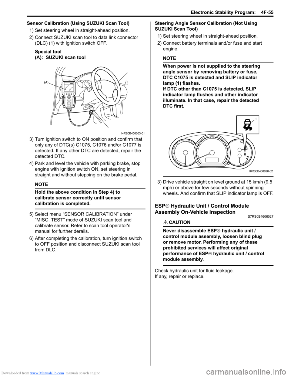
Sensor Calibration (Using SUZUKI Scan Tool)1) Set steering wheel in straight-ahead position.
2) Connect SUZUKI scan tool to data link connector (DLC) (1) with ignition switch OFF.
Special tool
(A): SUZUKI scan tool
3) Turn ignition switch to ON position and confirm that
only any of DTC(s) C1075, C1076 and/or C1077 is
detected. If any other DTC are detected, repair the
detected DTC.
4) Park and level the vehicle with parking brake, stop engine with ignition switch ON, set steering in
straight and without step ping on the brake pedal.
NOTE
Hold the above condition in Step 4) to
calibrate sensor correctly until sensor
calibration is completed.
5) Select menu “SENSOR CALIBRATION” under
“MISC. TEST” mode of SUZUKI scan tool and
calibrate sensor. Refer to scan tool operator's
manual for further derails.
6) After completing the calibra tion, turn ignition switch
to OFF position and disconnect SUZUKI scan tool
from DLC. Steering Angle Sensor Calibration (Not Using
SUZUKI Scan Tool)
1) Set steering wheel in straight-ahead position.
2) Connect battery terminals and/or fuse and start engine.
NOTE
When power is not supplied to the steering
angle sensor by removing battery or fuse,
DTC C1075 is detected and SLIP indicator
lamp (1) flashes.
If DTC other than C1075 is detected, SLIP
indicator lamp flushes and other indicator
illuminate. In that case, repair the detected
DTC first.
3) Drive vehicle straight on level ground at 15 km/h (9.5 mph) or above for few seconds without spinning
wheels. And confirm that SLIP indicator lamp is OFF.
ESP ® Hydraulic Unit / Control Module
Assembly On-Vehicle Inspection
S7RS0B4606027
CAUTION!
Never disassemble ESP ® hydraulic unit /
control module assembly, loosen blind plug
or remove motor. Pe rforming any of these
prohibited services will affect original
performance of ESP ® hydraulic unit / control
module assembly.
Check hydraulic unit for fluid leakage.
If any, repair or replace.
(A)
1
I4RS0B450003-01
1
I6RS0B460028-02