2007 SUZUKI SWIFT parking brake
[x] Cancel search: parking brakePage 796 of 1496

Downloaded from www.Manualslib.com manuals search engine 5A-152 Automatic Transmission/Transaxle:
12) Install 1st and reverse brake plate snap ring so that its both ends would be positioned in correct locations
as shown in figure.
13) Using special tools, meas ure 1st and reverse brake
piston stroke when compressed air (400 – 800 kPa,
4 – 8 kg/cm
2, 57 – 113 psi) is brown through oil hole.
Special tool
(A): 09900–20607
(B): 09900–20701
(C): 09952–06020
1st and reverse brake piston stroke
Standard: 0.791 – 1.489 mm (0.0311 – 0.0586 in.) 14) Install reduction drive gear (1) to transaxle case (3)
by using special tools and hydraulic press.
CAUTION!
• Do not use transaxle case as groundwork to press fit reduction drive gear.
• Do not give load more than 20 kN (2000 kg, 4410 lb) with hydraulic press. Otherwise, it
may result in damaging reduction drive
gear bearing.
NOTE
When replacing reduction drive gear, replace
it together with reduction driven gear as a
set.
Special tool
(A): 09951–18210
(B): 09944–78210
15) Install parking lock pawl (1) and spring (2). Apply A/T fluid to parking lock pawl sh aft, then insert it into
transaxle case.
[A]: Correct [B]: Incorrect
I2RH0B510268-01
I2RH0B510269-01
2. Stand that can slightly lift transaxle case.
I2RH0B510270-01
I2RH0B510271-01
Page 811 of 1496

Downloaded from www.Manualslib.com manuals search engine Automatic Transmission/Transaxle: 5A-167
Specifications
Tightening Torque SpecificationsS7RS0B5107001
NOTE
The specified tightening torque is also described in the following.
“Select Cable Components”
“Automatic Transaxle Unit Components”
“Automatic Transaxle Assembly Components”
“Oil Pump Assembly Components”
“Transaxle Rear Cover (O/D and 2nd Coast Brake Piston) Assembly Components”
“Valve Body Assembly Components”
“Differential Assembly Components”
Reference:
For the tightening torque of fastener not specified in this section, refer to “Fasteners Information in Section 0A”.
Fastening part
Tightening torque
Note
N ⋅mkgf-mlb-ft
A/T fluid drain plug 171.7 12.5 �) / �) / �)
Transmission range sensor bolt 5.5 0.55 4.0�) / �)
Output shaft speed sensor bolt 131.3 9.5 �) / �)
Input shaft speed sensor bolt 5.5 0.55 4.0�)
Valve body harness connector bolt 7.00.7 5.0 �)
Shift solenoid bolt 111.1 8.0 �)
Oil strainer bolt 101.0 7.5 �) / �)
Oil pan bolt 7.00.7 5.0 �) / �)
Transaxle and engine fastening bolt and nut 85 8.5 61.5�)
Drive plate to torque converter bolt 252.5 18.0 �)
Transaxle stiffener bolt 555.5 40�)
Starter motor bolt and nut 505.0 36.5 �)
Oil pump subassembly bolt 101.0 7.5 �)
Rear cover plug 7.5 0.75 5.5�)
Solenoid valve bolt 111.1 8.0 �)
Final gear bolt 787.8 56.5 �)
Torque converter housing plug 7.5 0.75 5.5�)
Lubrication tube clamp bolt 5.5 0.55 4.0�)
Fluid reservoir RH plate bolt 5.5 0.55 4.0�)
Torque converter housing bolt 292.9 21�) / �) / �)
Manual detent spring bolt 101.0 7.5 �)
Parking lock pawl bracket bolt 7.5 0.75 5.5�)
Rear cover bolt 252.5 18.0 �)
Fluid reservoir LH plate bolt 101.0 7.5 �)
Oil pump assembly bolt 252.5 18.0 �)
Transaxle case plug 7.5 0.75 5.5�)
Valve body harness connector bolt 5.5 0.55 4.0�)
Valve body bolt 111.1 8.0 �)
Fluid outlet union 252.5 18.0 �)
Fluid cooler pipe union bolt 222.2 16.0 �)
Fluid cooler pipe bracket bolt 101.0 7.5 �)
Fluid filler tube bolt 101.0 7.5 �)
Input shaft speed sensor bolt 111.1 8.0 �)
Harness bracket bolt 232.3 17.0 �)
Select cable clamp bolt 101.0 7.5 �)
Transmission range sensor lock nut 70.7 5.0 �)
Manual select lever nut 131.3 9.5 �)
Engine mounting LH bracket bolt 555.5 40.0
�)
Page 855 of 1496
Downloaded from www.Manualslib.com manuals search engine Clutch: 5C-3
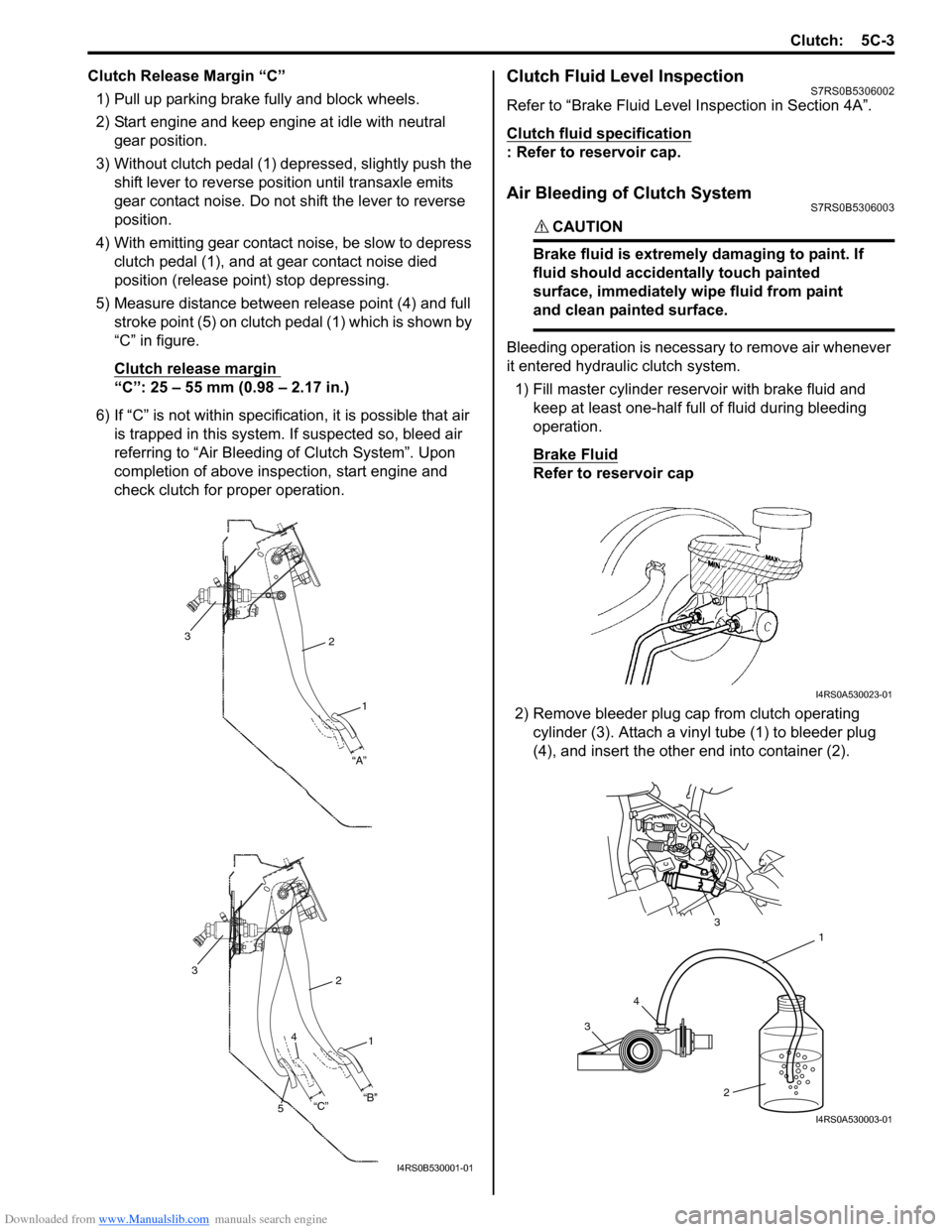
Clutch Release Margin “C”1) Pull up parking brake fully and block wheels.
2) Start engine and keep engine at idle with neutral gear position.
3) Without clutch pedal (1) dep ressed, slightly push the
shift lever to re verse position until transaxle emits
gear contact noise. Do not shift the lever to reverse
position.
4) With emitting gear contact noise, be slow to depress clutch pedal (1), and at gear contact noise died
position (release point) stop depressing.
5) Measure distance between release point (4) and full stroke point (5) on clutch pedal (1) which is shown by
“C” in figure.
Clutch release margin
“C”: 25 – 55 mm (0.98 – 2.17 in.)
6) If “C” is not within specificat ion, it is possible that air
is trapped in this system. If suspected so, bleed air
referring to “Air Bleeding of Clutch System”. Upon
completion of above inspection, start engine and
check clutch for proper operation.
Clutch Fluid Level InspectionS7RS0B5306002
Refer to “Brake Fluid Level Inspection in Section 4A”.
Clutch fluid specification
: Refer to reservoir cap.
Air Bleeding of Clutch SystemS7RS0B5306003
CAUTION!
Brake fluid is extremely damaging to paint. If
fluid should accidentally touch painted
surface, immediately wipe fluid from paint
and clean painted surface.
Bleeding operation is necessary to remove air whenever
it entered hydraulic clutch system.
1) Fill master cylinder reservoir with brake fluid and keep at least one-half full of fluid during bleeding
operation.
Brake Fluid
Refer to reservoir cap
2) Remove bleeder plug cap from clutch operating cylinder (3). Attach a vinyl tube (1) to bleeder plug
(4), and insert the other end into container (2).
2
1
“A”
3
2
1
3
“B”
“C”
4
5
I4RS0B530001-01
I4RS0A530023-01
3 4 1
2
3
I4RS0A530003-01
Page 1054 of 1496
Downloaded from www.Manualslib.com manuals search engine 8B-16 Air Bag System:
CAUTION!
• Be sure to perform “Air Bag Diagnostic System Check” before starting diagnosis according to flow.
• When measurement of resistance or voltage is required in this flow, use a tester along with a correct terminal adapter from special tool (Connector test adapter kit).
• When a check for proper connection is required, refer to “Inspection of Intermittent and Poor Connections”.
• If there is open circuit in the air bag wire harnes s, connector or terminal is found damaged, replace
the wire harness, connector and terminal as an assembly.
Flow Test Description
Step 1: Check combination meter power feed circuit.
Step 2: Check “AIR BAG” warning right circuit.
Troubleshooting
NOTE
Upon completion of inspection and repair work, perform the following items.
• Reconnect all air bag system components and ensure all components are properly mounted.
• Repeat “Air Bag Diagnostic System Check” to confirm that the trouble has been corrected.
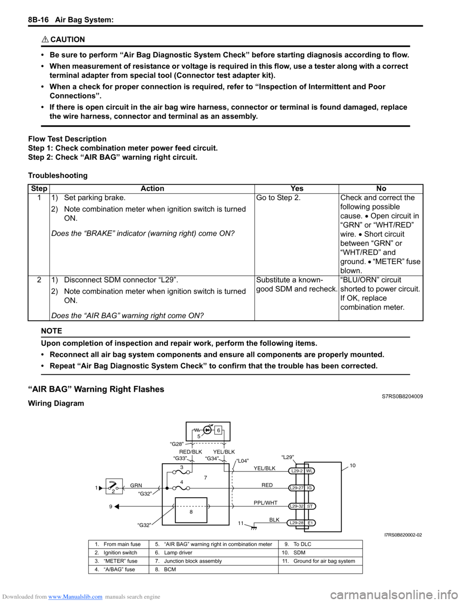
“AIR BAG” Warning Right FlashesS7RS0B8204009
Wiring Diagram Step Action Yes No
1 1) Set parking brake.
2) Note combination me ter when ignition switch is turned
ON.
Does the “BRAKE” in dicator (warning right) come ON? Go to Step 2. Check and correct the
following possible
cause. • Open circuit in
“GRN” or “WHT/RED”
wire. • Short circuit
between “GRN” or
“WHT/RED” and
ground. • “METER” fuse
blown.
2 1) Disconnect SDM connector “L29”.
2) Note combination me ter when ignition switch is turned
ON.
Does the “AIR BAG” warning right come ON? Substitute a known-
good SDM and recheck.
“BLU/ORN” circuit
shorted to power circuit.
If OK, replace
combination meter.
1
2 GRN
11
BLK
L29-27
L29-2
L29-28 WL
E1
IG
L29-32
ST
10
8
“L29”
RED
PPL/WHT
7
3
4 “L04”
“G34”
“G33”
“G28”
“G32”
5 6
“G32”
YEL/BLK
YEL/BLK
RED/BLK
9
I7RS0B820002-02
1. From main fuse 5. “AIR BAG” warning right in combination meter 9. To DLC
2. Ignition switch 6. Lamp driver 10. SDM
3. “METER” fuse 7. Junction block assembly 11. Ground for air bag system
4. “A/BAG” fuse 8. BCM
Page 1168 of 1496

Downloaded from www.Manualslib.com manuals search engine 9-ii Table of Contents
List of Connectors ........................................... 9A-103
C Connector .................................................... 9A-103
D Connector (M16A engine) ........................... 9A-104
E Connector .................................................... 9A-104
G Connector .................................................... 9A-106
J Connector ..................................................... 9A-108
K Connector .................................................... 9A-109
L Connector..................................................... 9A-109
M Connector (SPORT model) ......................... 9A-111
O Connector .................................................... 9A-111
R Connector .................................................... 9A-111
Lighting Systems .................................... 9B-1
Component Location ........... ................................9B-1
Lighting System Component s Location............... 9B-1
Interior Light System Location............................. 9B-2
Diagnostic Information and Procedures ............ 9B-2 Headlight Symptom Diagnosis ............................ 9B-2
Headlight Leveling System Symptom Diagnosis (If Equipped) ..................................... 9B-2
Turn Signal and Hazard Warning Light Symptom Diagnosis .......................................... 9B-3
Clearance, Tail and License Plate Light Symptom Diagnosis .......................................... 9B-3
Back-Up Light Symptom Diagnosis..................... 9B-4
Brake Light Symptom Diagnosis ......................... 9B-4
Front Fog Light Symptom Diagnosis (If Equipped) .......................................................... 9B-4
Interior Light Symptom Diagnosis ....................... 9B-5
Repair Instructions ..............................................9B-5 Headlight Housing Removal and Installation ...... 9B-5
Headlight Bulb Replacemen t............................... 9B-6
Headlight Aiming Adjustment with Screen .......... 9B-6
Headlight Switch (in Lighting Switch) Removal and Installation ................................... 9B-8
Headlight Switch (in Lighting Switch) Inspection .......................................................... 9B-8
Hazard Warning Switch Removal and Installation ......................................................... 9B-8
Hazard Warning Switch Inspection ..................... 9B-9
Brake Light Switch Inspection ............................. 9B-9
Turn Signal Light Switch (in Lighting Switch) Removal and Installation ................................... 9B-9
Turn Signal Light Switch (in Lighting Switch) Inspection .......................................................... 9B-9
Turn Signal and Hazard Warning Relay Removal and Installation ................................... 9B-9
Turn Signal and Hazard Warning Relay Inspection ........................................................ 9B-10
License Light Removal and Installation............. 9B-10
Front Fog Light Removal and Installation (If Equipped) ........................................................ 9B-11
Front Fog Light Bulb Replacement (If Equipped) ........................................................ 9B-11
Front Fog Light Switch Inspection (If Equipped) ........................................................ 9B-11
Front Fog Light Relay Inspection (If Equipped) ........................................................ 9B-11
Front Fog Light Aiming Adjustment with Screen (If Equipped) ....................................... 9B-12 Headlight Leveling Switch Inspection (If
Equipped) ........................................................ 9B-13
Headlight Leveling Actuator Inspection (If Equipped) ........................................................ 9B-13
Instrumentation / Driver Info. / Horn ...... 9C-1
Precautions ...........................................................9C-1 Precautions in Diagnosing Troubles for Combination Meter ............................................9C-1
General Description .............................................9C-1 CAN Communication System Description...........9C-1
Auto Volume Co ntrol System Description (If
Equipped) ..........................................................9C-3
Schematic and Routing Diagram ........................9C-4 Combination Meter Circuit Diagram ....................9C-4
Component Location ............ ...............................9C-6
Audio System Component Location ....................9C-6
Diagnostic Information and Procedures ............9C-6 Speedometer and VSS Symp tom Diagnosis ......9C-6
Tachometer Symptom Diagnosis ........................9C-6
Engine Coolant Temperature (ECT) Meter Symptom Diagnosis ..........................................9C-7
Fuel Meter Symptom Diagnosis ..........................9C-7
Low Fuel Warning Light Symptom Diagnosis .....9C-7
Oil Pressure Warning Light Symptom Diagnosis ..........................................................9C-8
Brake and Parking Brake Warning Light Symptom Diagnosis ..........................................9C-8
Seat Belt Reminder Light Symptom Diagnosis (If Equipped)......................................................9C-8
A/T Shift Position Indicator Symptom Diagnosis (A/T Model).......................................9C-9
Charge Warning Light Sy mptom Diagnosis ........9C-9
Main Beam (High Beam) Indicator Symptom Diagnosis ..........................................................9C-9
Warning Buzzer Circuit Sy mptom Diagnosis ....9C-10
Cigarette Lighter Symptom Diagnosis (If Equipped) ........................................................9C-10
Horn Symptom Diagnosis .................................9C-10
Information Display Symptom Diagnosis (If Equipped) ........................................................9C-11
Clock Symptom Diagnosis (If Equipped)...........9C-12
Audio System Symptom Diagnosis (If Equipped) ........................................................9C-12
Remote Audio Control Switch Symptom Diagnosis (If Equipped) ...................................9C-13
Navigation Symptom Diagnosis (If Equipped)...9C-14
Repair Instructions ............ ................................9C-14
Ignition Switch Removal and Installation...........9C-14
Ignition Switch Inspection..................................9C-14
Combination Meter Removal and Installation ...9C-15
Fuel Level Sensor Removal and Installation .....9C-15
Fuel Level Sensor Inspection ............................9C-15
Oil Pressure Switch Remova l and Installation ..9C-15
Oil Pressure Switch Inspec tion .........................9C-16
Engine Coolant Temperature (ECT) Sensor Inspection ........................................................9C-16
Brake Fluid Level Switch Inspection .................9C-16
Parking Brake Switch Inspec tion.......................9C-16
Page 1195 of 1496
Downloaded from www.Manualslib.com manuals search engine Wiring Systems: 9A-24
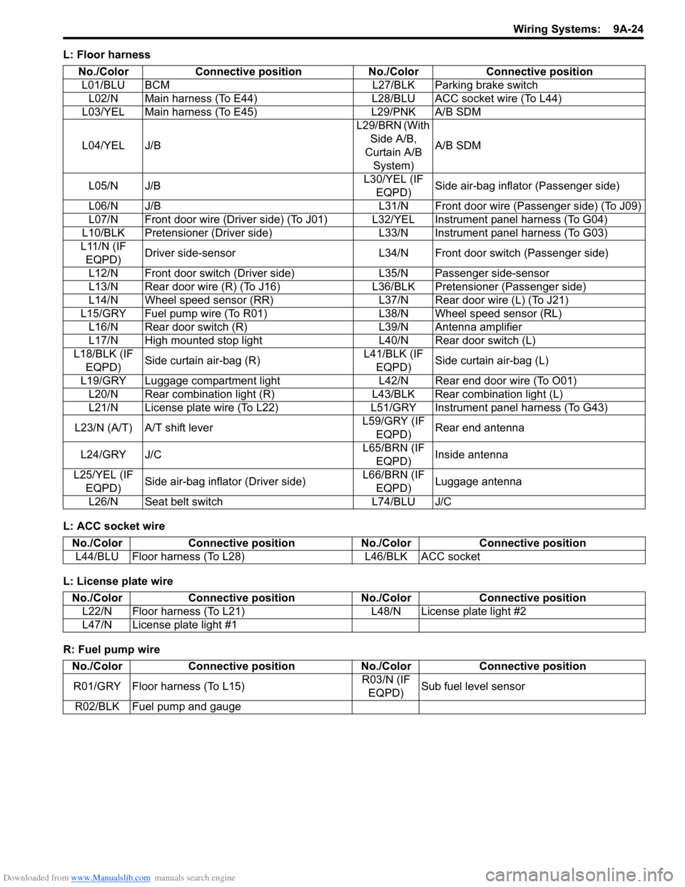
L: Floor harness
L: ACC socket wire
L: License plate wire
R: Fuel pump wireNo./Color Connective position No./Color Connective position
L01/BLU BCM L27/BLK Parking brake switch L02/N Main harness (To E44) L28/BLU ACC socket wire (To L44)
L03/YEL Main harness (To E45) L29/PNK A/B SDM
L04/YEL J/B L29/BRN (With
Side A/B,
Curtain A/B System) A/B SDM
L05/N J/B L30/YEL (IF
EQPD) Side air-bag inflator (Passenger side)
L06/N J/B L31/N Front door wire (Passenger side) (To J09)
L07/N Front door wire (Driver side) (To J01) L32/YEL Instrument panel harness (To G04)
L10/BLK Pretensioner (Driver side) L33/N Instrument panel harness (To G03)
L11/N (IF EQPD) Driver side-sensor L34/N Front door switch (Passenger side)
L12/N Front door switch (Driver side) L35/N Passenger side-sensor
L13/N Rear door wire (R) (To J16) L 36/BLK Pretensioner (Passenger side)
L14/N Wheel speed sensor (RR) L37/N Rear door wire (L) (To J21)
L15/GRY Fuel pump wire (To R01) L38/N Wheel speed sensor (RL)
L16/N Rear door switch (R) L39/N Antenna amplifier
L17/N High mounted stop light L40/N Rear door switch (L)
L18/BLK (IF EQPD) Side curtain air-bag (R) L41/BLK (IF
EQPD) Side curtain air-bag (L)
L19/GRY Luggage compartment light L42/N Rear end door wire (To O01) L20/N Rear combination light (R) L43/BLK Rear combination light (L)
L21/N License plate wire (To L22) L51/ GRY Instrument panel harness (To G43)
L23/N (A/T) A/T shift lever L59/GRY (IF
EQPD) Rear end antenna
L24/GRY J/C L65/BRN (IF
EQPD) Inside antenna
L25/YEL (IF EQPD) Side air-bag inflator (Driver side) L66/BRN (IF
EQPD) Luggage antenna
L26/N Seat belt switch L74/BLU J/C
No./Color Connective position No./Color Connective position
L44/BLU Floor harness (To L28) L46/BLK ACC socket
No./ColorConnective position No./Color Connective position
L22/N Floor harness (To L21) L48/N License plate light #2
L47/N License plate light #1
No./Color Connective position No./Color Connective position
R01/GRY Floor harness (To L15) R03/N (IF
EQPD) Sub fuel level sensor
R02/BLK Fuel pump and gauge
Page 1197 of 1496
Downloaded from www.Manualslib.com manuals search engine Wiring Systems: 9A-26
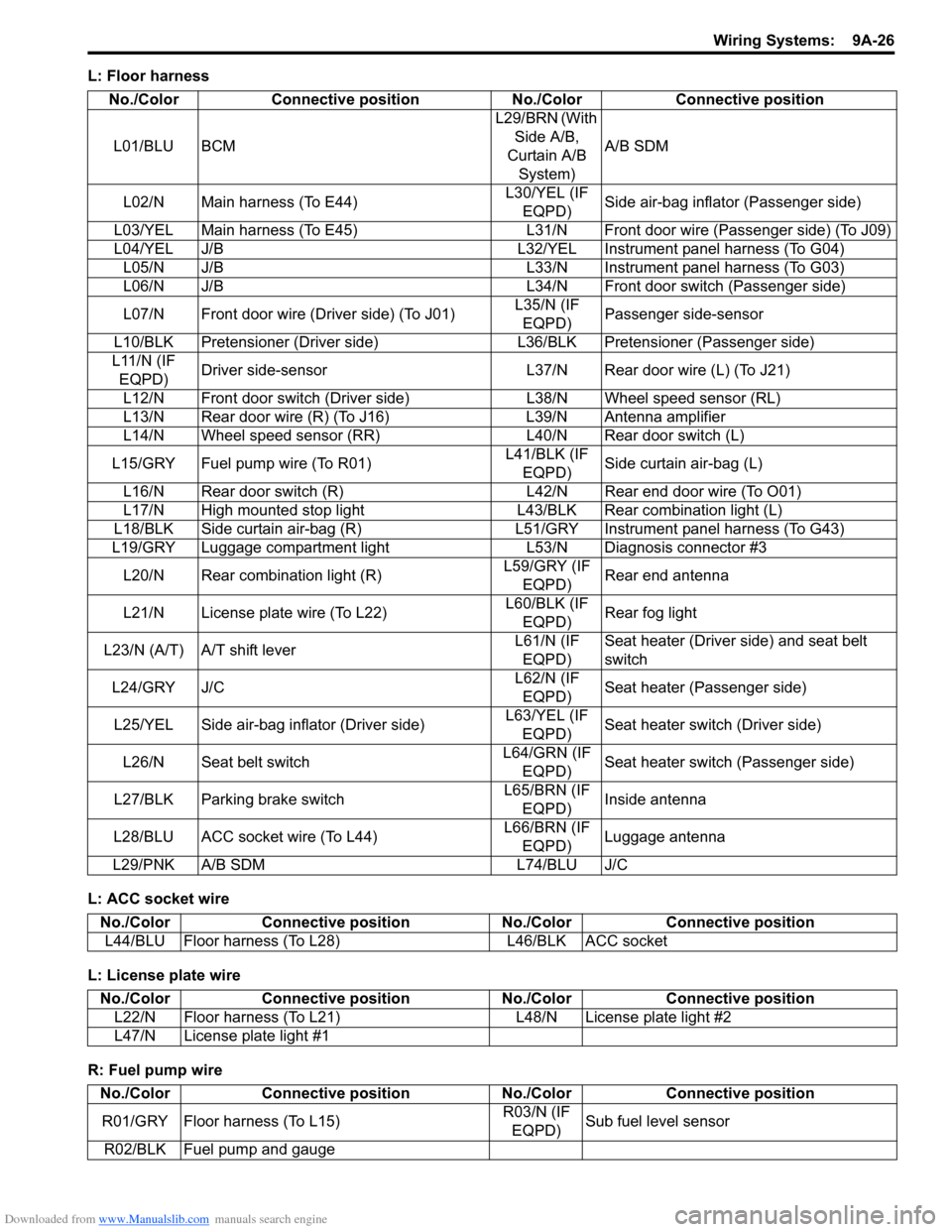
L: Floor harness
L: ACC socket wire
L: License plate wire
R: Fuel pump wireNo./Color Connective position No./Color Connective position
L01/BLU BCM L29/BRN (With
Side A/B,
Curtain A/B System) A/B SDM
L02/N Main harness (To E44) L30/YEL (IF
EQPD) Side air-bag inflator (Passenger side)
L03/YEL Main harness (To E45) L31/N Front door wire (Passenger side) (To J09)
L04/YEL J/B L32/YEL Instrument panel harness (To G04) L05/N J/B L33/N Instrument panel harness (To G03)
L06/N J/B L34/N Front door switch (Passenger side)
L07/N Front door wire (Driver side) (To J01) L35/N (IF
EQPD) Passenger side-sensor
L10/BLK Pretensioner (Driver side) L36/ BLK Pretensioner (Passenger side)
L11/N (IF EQPD) Driver side-sensor L37/N Rear door wire (L) (To J21)
L12/N Front door switch (Driver side) L38/N Wheel speed sensor (RL)
L13/N Rear door wire (R) (To J16) L39/N Antenna amplifier
L14/N Wheel speed sensor (RR) L40/N Rear door switch (L)
L15/GRY Fuel pump wire (To R01) L41/BLK (IF
EQPD) Side curtain air-bag (L)
L16/N Rear door switch (R) L42/N Rear end door wire (To O01)
L17/N High mounted stop light L43/BLK Rear combination light (L)
L18/BLK Side curtain air-bag (R) L51/GRY Instrument panel harness (To G43)
L19/GRY Luggage compartment light L53/N Diagnosis connector #3
L20/N Rear combin ation light (R) L59/GRY (IF
EQPD) Rear end antenna
L21/N License plate wire (To L22) L60/BLK (IF
EQPD) Rear fog light
L23/N (A/T) A/T shift lever L61/N (IF
EQPD) Seat heater (Driver side) and seat belt
switch
L24/GRY J/C L62/N (IF
EQPD) Seat heater (Passenger side)
L25/YEL Side air-bag inflator (Driver side) L63/YEL (IF
EQPD) Seat heater switch (Driver side)
L26/N Seat belt switch L64/GRN (IF
EQPD) Seat heater switch (Passenger side)
L27/BLK Parking brake switch L65/BRN (IF
EQPD) Inside antenna
L28/BLU ACC socket wire (To L44) L66/BRN (IF
EQPD) Luggage antenna
L29/PNK A/B SDM L74/BLU J/C
No./Color Connective position No./Color Connective position
L44/BLU Floor harness (To L28) L46/BLK ACC socket
No./ColorConnective position No./Color Connective position
L22/N Floor harness (To L21) L48/N License plate light #2
L47/N License plate light #1
No./Color Connective position No./Color Connective position
R01/GRY Floor harness (To L15) R03/N (IF
EQPD) Sub fuel level sensor
R02/BLK Fuel pump and gauge
Page 1199 of 1496
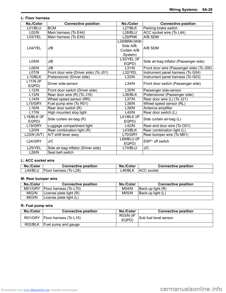
Downloaded from www.Manualslib.com manuals search engine Wiring Systems: 9A-28
L: Floor harness
L: ACC socket wire
M: Rear bumper wire
R: Fuel pump wireNo./Color Connective position No./Color Connective position
L01/BLU BCM L27/BLK Parking brake switch L02/N Main harness (To E44) L28/BLU ACC socket wire (To L44)
L03/YEL Main harness (To E45) L29/PNK A/B SDM
L04/YEL J/B L29/BRN (With
Side A/B,
Curtain A/B System) A/B SDM
L05/N J/B L30/YEL (IF
EQPD) Side air-bag inflator (Passenger side)
L06/N J/B L31/N Front door wire (Passenger side) (To J09)
L07/N Front door wire (Driver side) (To J01) L32/YEL Instrument panel harness (To G04)
L10/BLK Pretensioner (Driver side) L33/N Instrument panel harness (To G03)
L11/N (IF EQPD) Driver side-sensor L34/N Front door switch (Passenger side)
L12/N Front door switch (Driver side) L35/N Passenger side-sensor
L13/N Rear door wire (R) (To J16) L 36/BLK Pretensioner (Passenger side)
L14/N Wheel speed sensor (RR) L37/N Rear door wire (L) (To J21)
L15/GRY Fuel pump wire (To R01) L38/N Wheel speed sensor (RL)
L16/N Rear door switch (R) L39/N Antenna amplifier
L17/N High mounted stop light L40/N Rear door switch (L)
L18/BLK (IF EQPD) Side curtain air-bag (R) L41/BLK (IF
EQPD) Side curtain air-bag (L)
L19/GRY Luggage compartment light L42/N Rear end door wire (To O01) L20/N Rear combination light (R) L43/BLK Rear combination light (L)
L23/N (A/T) A/T shift lever assy L70/GRY Rear bumper wire (To M01)
L24/GRY J/C L69/BLU (IF
EQPD) ESP
® off switch
L25/YEL Side air-bag inflator (Driver side) L74/BLU J/C L26/N Seat belt switch
No./Color Connective position No./Color Connective position
L44/BLU Floor harness (To L28) L46/BLK ACC socket
No./ColorConnective position No./Color Connective position
M01/GRY Floor harness (To L70) M04/N Back-up light (R)
M02/N License plate light (R) M05/N Back-up light (L)
M03/N License plate light (L)
No./Color Connective position No./Color Connective position
R01/GRY Floor harness (To L15) R03/N (IF
EQPD) Sub fuel level sensor
R02/BLK Fuel pump and gauge