2007 SUZUKI SWIFT sensor-2
[x] Cancel search: sensor-2Page 45 of 1496
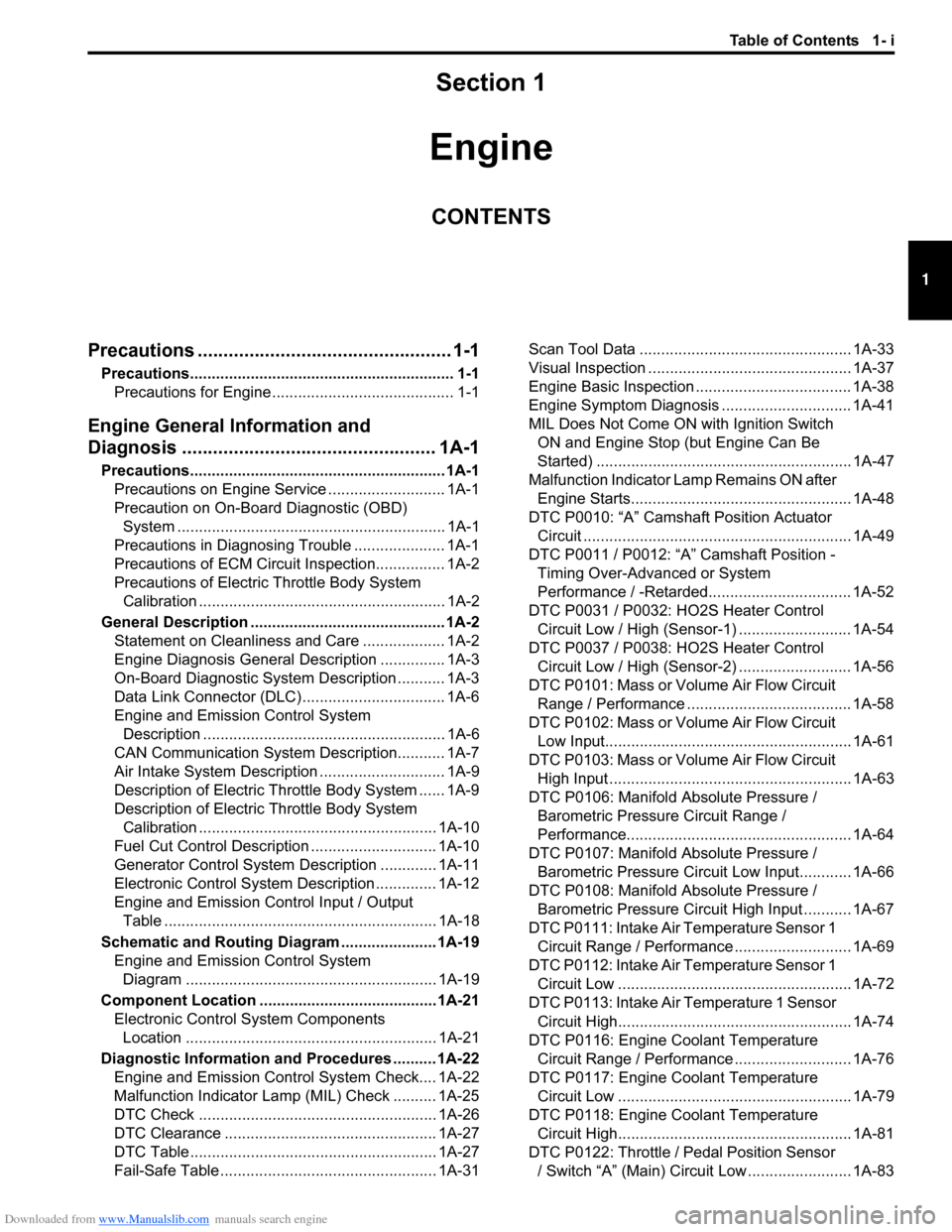
Downloaded from www.Manualslib.com manuals search engine Table of Contents 1- i
1
Section 1
CONTENTS
Engine
Precautions ................................................. 1-1
Precautions............................................................. 1-1
Precautions for Engine .......................................... 1-1
Engine General Information and
Diagnosis ............. .................................... 1A-1
Precautions........................................................... 1A-1
Precautions on Engine Service ........................... 1A-1
Precaution on On-Board Diagnostic (OBD) System .............................................................. 1A-1
Precautions in Diagnosing Trouble ..................... 1A-1
Precautions of ECM Circuit Inspection................ 1A-2
Precautions of Electric Throttle Body System
Calibration ......................................................... 1A-2
General Description ............................................. 1A-2 Statement on Cleanliness and Care ................... 1A-2
Engine Diagnosis General Description ............... 1A-3
On-Board Diagnostic System Description ........... 1A-3
Data Link Connector (DLC) ................................. 1A-6
Engine and Emission Control System Description ........................................................ 1A-6
CAN Communication System Description........... 1A-7
Air Intake System Description ............................. 1A-9
Description of Electric Throttle Body System ...... 1A-9
Description of Electric Throttle Body System Calibration ....................................................... 1A-10
Fuel Cut Control Description ............................. 1A-10
Generator Control System Description ............. 1A-11
Electronic Control System Description .............. 1A-12
Engine and Emission Control Input / Output Table ............................................................... 1A-18
Schematic and Routing Diagram ...................... 1A-19 Engine and Emission Control System Diagram .......................................................... 1A-19
Component Locatio n ......................................... 1A-21
Electronic Control System Components Location .......................................................... 1A-21
Diagnostic Information and Procedures .......... 1A-22 Engine and Emission Control System Check.... 1A-22
Malfunction Indicator Lamp (MIL) Check .......... 1A-25
DTC Check ....................................................... 1A-26
DTC Clearance ................................................. 1A-27
DTC Table ......................................................... 1A-27
Fail-Safe Table ................ .................................. 1A-31 Scan Tool Data ................................................. 1A-33
Visual Inspection ............................................... 1A-37
Engine Basic Inspection .................................... 1A-38
Engine Symptom Diagnosis .............................. 1A-41
MIL Does Not Come ON with Ignition Switch
ON and Engine Stop (but Engine Can Be
Started) ........................................................... 1A-47
Malfunction Indicator Lamp Remains ON after Engine Starts................................................... 1A-48
DTC P0010: “A” Camshaft Position Actuator Circuit .............................................................. 1A-49
DTC P0011 / P0012: “A” Camshaft Position - Timing Over-Advanced or System
Performance / -Retarded................................. 1A-52
DTC P0031 / P0032: HO2S Heater Control Circuit Low / High (Sensor-1) .......................... 1A-54
DTC P0037 / P0038: HO2S Heater Control Circuit Low / High (Sensor-2) .......................... 1A-56
DTC P0101: Mass or Volume Air Flow Circuit Range / Performance ...................................... 1A-58
DTC P0102: Mass or Volume Air Flow Circuit Low Input......................................................... 1A-61
DTC P0103: Mass or Volume Air Flow Circuit High Input ........................................................ 1A-63
DTC P0106: Manifold Absolute Pressure /
Barometric Pressure Circuit Range /
Performance.................................................... 1A-64
DTC P0107: Manifold Absolute Pressure /
Barometric Pressure Circ uit Low Input............ 1A-66
DTC P0108: Manifold Absolute Pressure /
Barometric Pressure Circ uit High Input ........... 1A-67
DTC P0111: Intake Air Temperature Sensor 1 Circuit Range / Performance ........................... 1A-69
DTC P0112: Intake Air Temperature Sensor 1 Circuit Low ...................................................... 1A-72
DTC P0113: Intake Air Temperature 1 Sensor Circuit High...................................................... 1A-74
DTC P0116: Engine Coolant Temperature Circuit Range / Performance ........................... 1A-76
DTC P0117: Engine Coolant Temperature Circuit Low ...................................................... 1A-79
DTC P0118: Engine Coolant Temperature Circuit High...................................................... 1A-81
DTC P0122: Throttle / Pedal Position Sensor / Switch “A” (Main) Circuit Low ........................ 1A-83
Page 66 of 1496
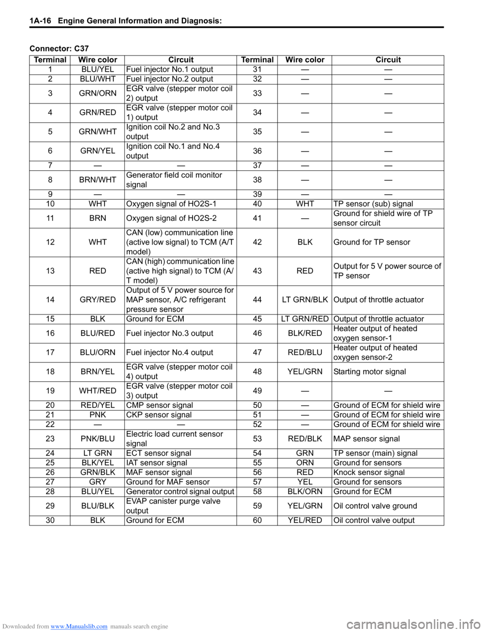
Downloaded from www.Manualslib.com manuals search engine 1A-16 Engine General Information and Diagnosis:
Connector: C37Terminal Wire color Circuit Terminal Wire color Circuit 1 BLU/YEL Fuel injector No.1 output 31 — —
2 BLU/WHT Fuel injector No.2 output 32 — —
3GRN/ORN EGR valve (stepper motor coil
2) output 33 — —
4 GRN/RED EGR valve (stepper motor coil
1) output 34 — —
5 GRN/WHT Ignition coil No.2 and No.3
output 35 — —
6 GRN/YEL Ignition coil No.1 and No.4
output 36 — —
7— — 37— —
8 BRN/WHT Generator field coil monitor
signal 38 — —
9— — 39— —
10 WHT Oxygen signal of HO2S-1 40 WHT TP sensor (sub) signal
11 BRN Oxygen signal of HO2S-2 41 — Ground for shield wire of TP
sensor circuit
12 WHT CAN (low) communication line
(active low signal) to TCM (A/T
model) 42 BLK Ground for TP sensor
13 RED CAN (high) communication line
(active high signal) to TCM (A/
T model) 43 RED
Output for 5 V power source of
TP sensor
14 GRY/RED Output of 5 V power source for
MAP sensor, A/C refrigerant
pressure sensor 44 LT GRN/BLK Output of throttle actuator
15 BLK Ground for ECM 45 LT GRN/RE D Output of throttle actuator
16 BLU/RED Fuel injector No.3 output 46 BLK/RED Heater output of heated
oxygen sensor-1
17 BLU/ORN Fuel injector No.4 output 47 RED/BLU Heater output of heated
oxygen sensor-2
18 BRN/YEL EGR valve (stepper motor coil
4) output 48 YEL/GRN Starting motor signal
19 WHT/RED EGR valve (stepper motor coil
3) output 49 — —
20 RED/YEL CMP sensor signal 50 — G round of ECM for shield wire
21 PNK CKP sensor signal 51 — Ground of ECM for shield wire
22 — — 52 — Ground of ECM for shield wire
23 PNK/BLU Electric load current sensor
signal 53 RED/BLK MAP sensor signal
24 LT GRN ECT sensor signal 54 GRN TP sensor (main) signal
25 BLK/YEL IAT sensor signal 55 ORN Ground for sensors
26 GRN/BLK MAF sensor signal 56 RED Knock sensor signal
27 GRY Ground for MAF sensor 57 YEL Ground for sensors
28 BLU/YEL Generator control signal output 58 BLK/ORN Ground for ECM
29 BLU/BLK EVAP canister purge valve
output 59 YEL/GRN Oil control valve ground
30 BLK Ground for ECM 60 YEL/RED Oil control valve output
Page 78 of 1496
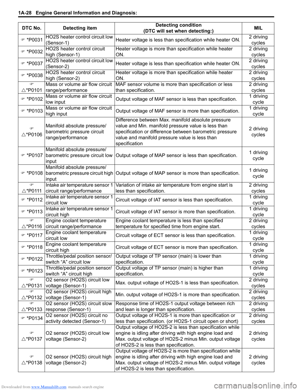
Downloaded from www.Manualslib.com manuals search engine 1A-28 Engine General Information and Diagnosis:
�) *P0031 HO2S heater control circuit low
(Sensor-1) Heater voltage is less than specification while heater ON. 2 driving
cycles
�) *P0032 HO2S heater control circuit
high (Sensor-1) Heater voltage is more than
specification while heater
ON. 2 driving
cycles
�) *P0037 HO2S heater control circuit low
(Sensor-2) Heater voltage is less than specification while heater ON. 2 driving
cycles
�) *P0038 HO2S heater control circuit
high (Sensor-2) Heater voltage is more than
specification while heater
ON. 2 driving
cycles
�)
�U *P0101 Mass or volume air flow circuit
range/performance MAF sensor volume is more
than specification or less
than specification. 2 driving
cycles
�) *P0102 Mass or volume air flow circuit
low input Output voltage of MAF sensor is less than specification. 1 driving
cycle
�) *P0103 Mass or volume air flow circuit
high input Output voltage of MAF sensor is more than specification. 1 driving
cycle
�)
�U *P0106 Manifold absolute pressure/
barometric pressure circuit
range/performance Difference between Max. manifold absolute pressure
value and Min. manifold pressure value is less than
specification or difference between barometric pressure
value and manifold pressure value is less than
specification
2 driving
cycles
�) *P0107 Manifold absolute pressure/
barometric pressure circuit low
input Output voltage of MAP sensor
is less than specification.1 driving
cycle
�) *P0108 Manifold absolute pressure/
barometric pressure circuit high
input Output voltage of MAP sensor is more than specification.
1 driving
cycle
�)
�U *P0111 Intake air temperature sensor 1
circuit range/performance Variation of intake air temperature from engine start is
less than specification. 2 driving
cycles
�) *P0112 Intake air temperature sensor 1
circuit low Circuit voltage of IAT sensor is less than specification. 1 driving
cycle
�) *P0113 Intake air temperature sensor 1
circuit hig
h Circuit voltage of IAT sensor
is more than specification. 1 driving
cycle
�)
�U *P0116 Engine coolant temperature
circuit range/performance Engine coolant temperature is less than specified
temperature for specified time from engine start. 2 driving
cycles
�) *P0117 Engine coolant temperature
circuit low Circuit voltage of ECT sensor
is less than specification. 1 driving
cycle
�) *P0118 Engine coolant temperature
circuit high Circuit voltage of ECT sensor
is more than specification. 1 driving
cycle
�) *P0122 Throttle/pedal position sensor/
switch “A” circuit low Output voltage of TP sensor (main) is lower than
specification. 1 driving
cycle
�) *P0123 Throttle/pedal position sensor/
switch “A” circuit high Output voltage of TP sensor (main) is higher than
specification. 1 driving
cycle
�)
�U *P0131 O2 sensor (HO2S) circuit low
voltage (Sensor-1)
Max. output voltage of HO2S-1
is less than specification.2 driving
cycles
�)
�U *P0132 O2 sensor (HO2S) circuit high
voltage (Sensor-1)
Min. output voltage of HO2S-1
is more than specification. 2 driving
cycles
�)
�U *P0133 O2 sensor (HO2S) circuit slow
response (Sensor-1) Response time of HO2S-1 output voltage between rich
and lean is longer than specification. 2 driving
cycles
�) *P0134 O2 sensor (HO2S) circuit no
activity detected (Sensor-1) Output voltage of HO2S-1 is
more than specification or
less than specification. (or HO2S-1 circuit open or short) 2 driving
cycles
�)
�U *P0137 O2 sensor (HO2S) circuit low
voltage (Sensor-2) Output voltage of HO2S-2 is
less than specification while
engine is idling after driving with high engine load and
Max. output voltage of HO2S-2 minus Min. output voltage
of HO2S-2 is less than specification. 2 driving
cycles
�)
�U *P013
8 O2 sensor (HO2S) circuit high
voltage (Sensor-2) Output voltage of HO2S-2 is
more than specification while
engine is idling after driving with high engine load and
Max. output voltage of HO2S-2 minus Min. output voltage
of HO2S-2 is less than specification. 2 driving
cycles
DTC No. Detecting item
Detecting condition
(DTC will set when detecting:) MIL
Page 79 of 1496
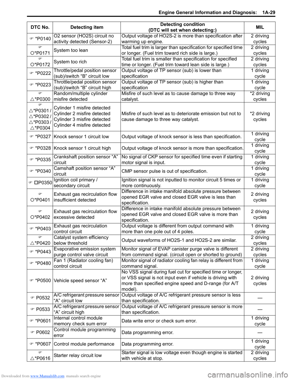
Downloaded from www.Manualslib.com manuals search engine Engine General Information and Diagnosis: 1A-29
�) *P0140 O2 sensor (HO2S) circuit no
activity detected (Sensor-2) Output voltage of HO2S-2 is more than specification after
warming up engine. 2 driving
cycles
�)
�{ *P0171 System too lean Total fuel trim is larger than
specification for specified time
or longer. (Fuel trim towa rd rich side is large.) 2 driving
cycles
�)
�{ *P0172 System too rich Total fuel trim is smaller th
an specification for specified
time or longer. (Fue l trim toward lean side is large.) 2 driving
cycles
�) *P0222 Throttle/pedal position sensor
(sub)/switch “B” circuit low Output voltage of TP sensor (sub) is lower than
specification 1 driving
cycle
�) *P0223 Throttle/pedal position sensor
(sub)/switch “B” circuit high Output voltage of TP sensor (sub) is higher than
specification 1 driving
cycle
�)
�U *P0300 Random/multiple cylinder
misfire detected Misfire of such level as to cause damage to three way
catalyst. *2 driving
cycles
�)
�U *P0301 /
�U *P0302 /
�U *P0303 /
�U *P0304 Cylinder 1 misfire detected
Cylinder 2 misfire detected
Cylinder 3 misfire detected
Cylinder 4 misfire detected
Misfire of such level as to deteriorate emission but not to
cause damage to three way catalyst.
*2 driving
cycles
�) *P0327 Knock sensor 1 circuit low Output voltage of knock sensor is less than specification.1 driving
cycle
�) *P0328 Knock sensor 1 circuit high Output volta ge of knock sensor is more than specification.1 driving
cycle
�) *P0335 Crankshaft position sensor “A”
circuit No signal of CKP sensor for sp
ecified time even if starting
motor signal is input. 1 driving
cycle
�) *P0340 Camshaft position sensor “A”
circuit CMP sensor pulse is out of specification. 1 driving
cycle
�) �† P0350 Ignition c
oil primary /
secondary circuit Ignition signal is not inputted to monitor circuit 5 times or
more continuously. 1 driving
cycle
�)
�{ *P0401 Exhaust gas recirculation flow
insufficient detected Difference in intake manifold absolute pressure between
opened EGR valve and closed EGR valve is less than
specification. 2 driving
cycles
�)
�{ *P0402 Exhaust gas recirculation flow
excessive detected Difference in intake manifold absolute pressure between
opened EGR valve and closed EGR valve is more than
specification. 2 driving
cycles
�) *P0403 Exhaust gas recirculation
control circuit Output voltage is different from output command with
more than one pole out of 4 poles. 1 driving
cycle
�)
�U *P0420 Catalyst system efficiency
below threshold
Output waveforms of HO2S-1 and HO2S-2 are similar. 2 driving
cycles
�) *P0443 Evaporative emission system
purge control valve circuit Monitor signal of EVAP canister purge valve is different
from command signal. (circuit open or shorted to ground) 2 driving
cycles
�) *P0480 Fan 1 (Radiator cooling fan)
control circuit Monitor signal of radiator cooling fan relay is different from
command signal. 1 driving
cycle
�) *P0500 Vehicle speed sensor “A” No VSS signal during fuel cut fo
r specified time or longer,
or VSS signal is not input even if vehicle is driving with
more than specified engine speed and D-range (for A/T
model). 2 driving
cycles
�) P0532 A/C refrigerant pressure sensor
“A” circuit low Output voltage of A/C refrigerant pressure sensor is less
than specification.
—
�) P0533 A/C refrigerant pressure sensor
“A” circuit high Output voltage of A/C refrigerant pressure sensor is more
than specification.
—
�) *P0601 Internal control module
memory check sum error Data write error or check sum error. 1 driving
cycle
�) P0602 Control module programming
error Data programming error.
—
�) *P0607 Control module performance Data programming error. 1 driving
cycle
�)
�U *P061
6Starter relay circuit low Starter signal is low voltage even though engine is started
with vehicle at stop. 2 driving
cycles
DTC No. Detecting item
Detecting condition
(DTC will set when detecting:) MIL
Page 86 of 1496
Downloaded from www.Manualslib.com manuals search engine 1A-36 Engine General Information and Diagnosis:
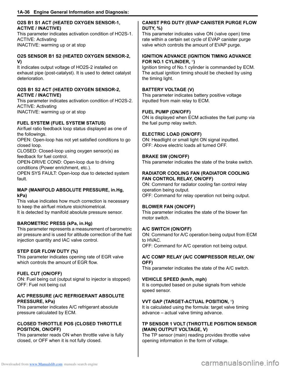
O2S B1 S1 ACT (HEATED OXYGEN SENSOR-1,
ACTIVE / INACTIVE)
This parameter indicates activation condition of HO2S-1.
ACTIVE: Activating
INACTIVE: warming up or at stop
O2S SENSOR B1 S2 (HEATED OXYGEN SENSOR-2,
V)
It indicates output voltage of HO2S-2 installed on
exhaust pipe (post-catalyst). It is used to detect catalyst
deterioration.
O2S B1 S2 ACT (HEATED OXYGEN SENSOR-2,
ACTIVE / INACTIVE)
This parameter indicates acti vation condition of HO2S-2.
ACTIVE: Activating
INACTIVE: warming up or at stop
FUEL SYSTEM (FUEL SYSTEM STATUS)
Air/fuel ratio feedback loop status displayed as one of
the followings.
OPEN: Open-loop has not yet satisfied conditions to go
closed loop.
CLOSED: Closed-loop using oxygen sensor(s) as
feedback for fuel control.
OPEN-DRIVE COND: Open-loop due to driving
conditions (Power enrichment, etc.).
OPEN SYS FAULT: Open-loop due to detected system
fault.
MAP (MANIFOLD ABSOLUTE PRESSURE, in.Hg,
kPa)
This value indicates how much correction is necessary
to keep the air/fuel mixture stoichiometrical.
It is detected by manifold absolute pressure sensor.
BAROMETRIC PRESS (kPa, in.Hg)
This parameter represents a measurement of barometric
air pressure and is used for al titude correction of the fuel
injection quantity and IAC valve control.
STEP EGR FLOW DUTY (%)
This parameter indicates opening rate of EGR valve
which controls the amount of EGR flow.
FUEL CUT (ON/OFF)
ON: Fuel being cut (output signal to injector is stopped)
OFF: Fuel not being cut
A/C PRESSURE (A/C REFRIGERANT ABSOLUTE
PRESSURE, kPa)
This parameter indicates A/C refrigerant absolute
pressure calculated by ECM.
CLOSED THROTTLE PO S (CLOSED THROTTLE
POSITION, ON/OFF)
This parameter reads ON wh en throttle valve is fully
closed, or OFF when it is not fully closed. CANIST PRG DUTY (EVAP CANISTER PURGE FLOW
DUTY, %)
This parameter indicates valve ON (valve open) time
rate within a certain set cycle of EVAP canister purge
valve which controls the amount of EVAP purge.
IGNITION ADVANCE (IGNITION TIMING ADVANCE
FOR NO.1 CYLINDER,
°)
Ignition timing of No.1 cylinder is commanded by ECM.
The actual ignition timing should be checked by using
the timing light.
BATTERY VOLTAGE (V)
This parameter indicates battery positive voltage
inputted from main relay to ECM.
FUEL PUMP (ON/OFF)
ON is displayed when ECM activates the fuel pump via
the fuel pump relay switch.
ELECTRIC LOAD (ON/OFF)
ON: Headlight or small light ON signal inputted.
OFF: Above electric loads all turned OFF.
BRAKE SW (ON/OFF)
This parameter indicates the state of the brake switch.
RADIATOR COOLING FAN (RADIATOR COOLING
FAN CONTROL RELAY, ON/OFF)
ON: Command for radiator cooling fan control relay
operation being output.
OFF: Command for relay operation not being output.
BLOWER FAN (ON/OFF)
This parameter indicates the state of the blower fan
motor switch.
A/C SWITCH (ON/OFF)
ON: Command for A/C operatio n being output from ECM
to HVAC.
OFF: Command for A/C oper ation not being output.
A/C COMP RELAY (A/C COMPRESSOR RELAY, ON/
OFF)
This parameter indicates the state of the A/C switch.
VEHICLE SPEED (km/h, mph)
It is computed based on pulse signals from vehicle
speed sensor.
VVT GAP (TARGET-ACTUAL POSITION, °)
It is calculated using the formula: target valve timing
advance – actual valve timing advance.
TP SENSOR 1 VOLT (THROTTLE POSITION SENSOR
(MAIN) OUTPUT VOLTAGE, V)
The TP sensor (main) reading provides throttle valve
opening information in the form of voltage.
Page 106 of 1496
Downloaded from www.Manualslib.com manuals search engine 1A-56 Engine General Information and Diagnosis:
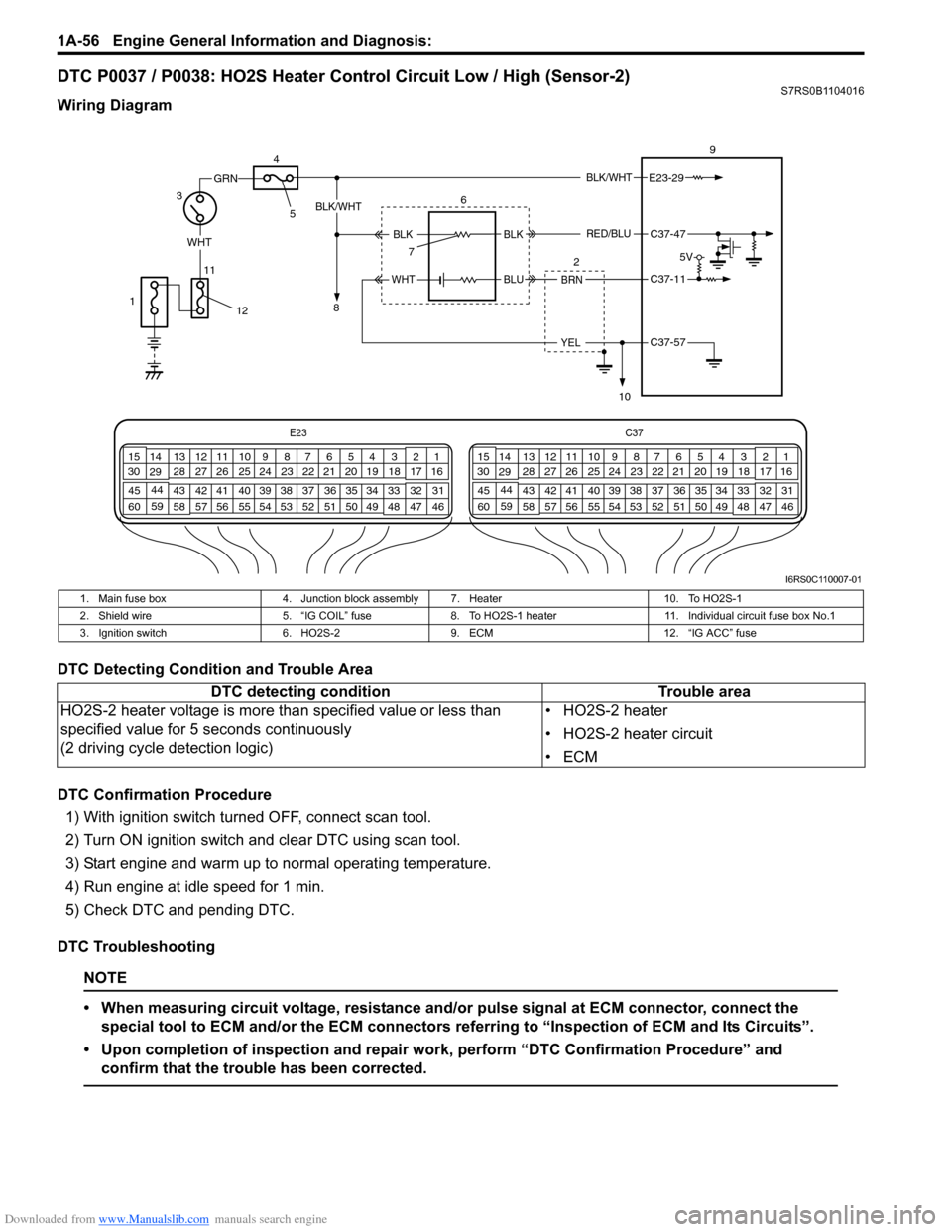
DTC P0037 / P0038: HO2S Heater Control Circuit Low / High (Sensor-2)S7RS0B1104016
Wiring Diagram
DTC Detecting Condition and Trouble Area
DTC Confirmation Procedure1) With ignition switch turned OFF, connect scan tool.
2) Turn ON ignition switch and clear DTC using scan tool.
3) Start engine and warm up to normal operating temperature.
4) Run engine at idle speed for 1 min.
5) Check DTC and pending DTC.
DTC Troubleshooting
NOTE
• When measuring circuit voltage, resistance and/ or pulse signal at ECM connector, connect the
special tool to ECM and/or the ECM connectors re ferring to “Inspection of ECM and Its Circuits”.
• Upon completion of inspection and repair work, perform “DTC Confirmation Procedure” and confirm that the trouble has been corrected.
E23 C37
34
1819
567
1011
17
20
47 46
495051
2122
52 16
25 9
24
14
29
55
57 54 53
59
60 58 2
262728
15
30
56 4832 31
34353637
40
42 39 38
44
45 43 41 331
1213
238
34
1819
567
1011
17
20
47 46
495051
2122
52 16
25 9
24
14
29
55
57 54 53
59
60 58 2
262728
15
30
56 4832 31
34353637
40
42 39 38
44
45 43 41 331
1213
238
BLK/WHT
WHT
11
GRN
3 9
E23-29
BRN
YEL
BLK/WHT
BLKC37-47
C37-11
C37-57
6
2
7
10
BLK
BLUWHT
RED/BLU
1
4
5
8
12
5V
I6RS0C110007-01
1. Main fuse box 4. Junction block assembly 7. Heater 10. To HO2S-1
2. Shield wire 5. “IG COIL” fuse8. To HO2S-1 heater 11. Individual circuit fuse box No.1
3. Ignition switch 6. HO2S-29. ECM 12. “IG ACC” fuse
DTC detecting condition Trouble area
HO2S-2 heater voltage is more than specified value or less than
specified value for 5 seconds continuously
(2 driving cycle detection logic) • HO2S-2 heater
• HO2S-2 heater circuit
•ECM
Page 144 of 1496

Downloaded from www.Manualslib.com manuals search engine 1A-94 Engine General Information and Diagnosis:
DTC P0137 / P0138: O2 Sensor (HO2S) Circuit Low Voltage / High Voltage (Sensor-2)S7RS0B1104034
Wiring Diagram
DTC Detecting Condition and Trouble Area
E23C37
34
1819
567
1011
17
20
47 46
495051
2122
52 16
25 9
24
14
29
55
57 54 53
59
60 58 2
262728
15
30
56 4832 31
34353637
40
42 39 38
44
45 43 41 331
1213
238
34
1819
567
1011
17
20
47 46
495051
2122
52 16
25 9
24
14
29
55
57 54 53
59
60 58 2
262728
15
30
56 4832 31
34353637
40
42 39 38
44
45 43 41 331
1213
238
BLK/WHT
WHT
11
GRN
3 9
E23-29
BRN
YEL
BLK/WHT
BLKC37-47
C37-11
C37-57
6
2
7
10
BLK
BLUWHT
RED/BLU
1
4
5
8
12
5V
I6RS0C110007-01
1. Main fuse box 4. Junction block assembly 7. Heater 10. To HO2S-1
2. Shield wire 5. “IG COIL” fuse8. To HO2S-1 heater 11. Individual circuit fuse box No.1
3. Ignition switch 6. HO2S-29. ECM 12. “IG ACC” fuse
DTC detecting condition Trouble area
DTC P0137:
HO2S-2 voltage is lower th an 0.4 V while engine is idling after driving with
high engine load (high speed) for specified time. And HO2S-2 max. voltage
minus HO2S-2 min. voltage is less than 0.1 V for 40 sec continuously.
(2 driving cycle detection logic)
DTC P0138:
HO2S-2 voltage is higher than 0.95 V while engine is idling after driving
with high engine load (high speed) for specified time. And HO2S-2 max.
voltage minus HO2S-2 min. voltage is less than 0.1 V for 40 sec
continuously.
(2 driving cycle detection logic) •HO2S-2
• HO2S-2 circuit
• Fuel system
•ECM
• Fuel shortage
• Exhaust system
• Air intake system
Page 146 of 1496
Downloaded from www.Manualslib.com manuals search engine 1A-96 Engine General Information and Diagnosis:
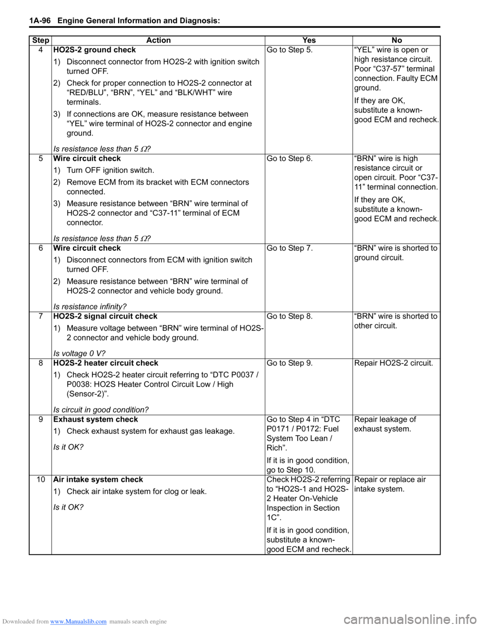
4HO2S-2 ground check
1) Disconnect connector from HO 2S-2 with ignition switch
turned OFF.
2) Check for proper connection to HO2S-2 connector at “RED/BLU”, “BRN”, “YEL” and “BLK/WHT” wire
terminals.
3) If connections are OK, m easure resistance between
“YEL” wire terminal of HO2S-2 connector and engine
ground.
Is resistance less than 5
Ω? Go to Step 5. “YEL” wire is open or
high resistance circuit.
Poor “C37-57” terminal
connection. Faulty ECM
ground.
If they are OK,
substitute a known-
good ECM and recheck.
5 Wire circuit check
1) Turn OFF ignition switch.
2) Remove ECM from its br acket with ECM connectors
connected.
3) Measure resistance between “BRN” wire terminal of HO2S-2 connector and “C37-11” terminal of ECM
connector.
Is resistance less than 5
Ω? Go to Step 6. “BRN” wire is high
resistance circuit or
open circuit. Poor “C37-
11” terminal connection.
If they are OK,
substitute a known-
good ECM and recheck.
6 Wire circuit check
1) Disconnect connectors from ECM with ignition switch
turned OFF.
2) Measure resistance between “BRN” wire terminal of HO2S-2 connector and vehicle body ground.
Is resistance infinity? Go to Step 7. “BRN” wire is shorted to
ground circuit.
7 HO2S-2 signal circuit check
1) Measure voltage between “BRN” wire terminal of HO2S-
2 connector and vehicle body ground.
Is voltage 0 V? Go to Step 8. “BRN” wire is shorted to
other circuit.
8 HO2S-2 heater circuit check
1) Check HO2S-2 heater circuit referring to “DTC P0037 /
P0038: HO2S Heater Control Circuit Low / High
(Sensor-2)”.
Is circuit in good condition? Go to Step 9. Repair HO2S-2 circuit.
9 Exhaust system check
1) Check exhaust system for exhaust gas leakage.
Is it OK? Go to Step 4 in “DTC
P0171 / P0172: Fuel
System Too Lean /
Rich”.
If it is in good condition,
go to Step 10.Repair leakage of
exhaust system.
10 Air intake system check
1) Check air intake system for clog or leak.
Is it OK? Check HO2S-2 referring
to “HO2S-1 and HO2S-
2 Heater On-Vehicle
Inspection in Section
1C”.
If it is in good condition,
substitute a known-
good ECM and recheck.Repair or replace air
intake system.
Step Action Yes No