2007 SUZUKI SWIFT Oil pan and oil strainer
[x] Cancel search: Oil pan and oil strainerPage 48 of 1496

Downloaded from www.Manualslib.com manuals search engine 1-iv Table of Contents
Engine Lubrication System.....................1E-1
General Description ............................................. 1E-1
Engine Lubrication Description ........................... 1E-1
Diagnostic Information and Procedures ............ 1E-2 Oil Pressure Check ............................................. 1E-2
Repair Instructions ........... ................................... 1E-3
Heat Exchanger Components ............................. 1E-3
Heat Exchanger On-Vehicle Inspection .............. 1E-4
Heat Exchanger Removal and Installation .......... 1E-4
Oil Pan and Oil Pump Strainer Components....... 1E-5
Oil Pan and Oil Pump Strainer Removal and
Installation ......................................................... 1E-5
Oil Pan and Oil Pump Stra iner Cleaning ............. 1E-7
Oil Pump Components ........................................ 1E-8
Oil Pump Removal and Installation ..................... 1E-8
Oil Pump Disassembly and Reassembly ............ 1E-8
Oil Pump Inspection ............................................ 1E-9
Specifications .... ................................................. 1E-11
Tightening Torque Specifications ...................... 1E-11
Special Tools and Equipmen t ........................... 1E-11
Recommended Service Material ....................... 1E-11
Special Tool ...................................................... 1E-11
Engine Cooling System ..... ...................... 1F-1
General Description .......... ................................... 1F-1
Cooling System Descriptio n ................................ 1F-1
Coolant Description ............................................. 1F-1
Schematic and Routing Diagram ........................ 1F-2 Coolant Circulation .............................................. 1F-2
Diagnostic Information and Procedures ............ 1F-4 Engine Cooling Symptom Diagnosis ................... 1F-4
Repair Instructions ........... ................................... 1F-5
Cooling System Components.............................. 1F-5
Coolant Level Check ........................................... 1F-6
Engine Cooling System Inspection and Cleaning ............................................................ 1F-6
Cooling System Draining.. ................................... 1F-6
Cooling System Flush and Refill ......................... 1F-7
Cooling Water Pipes or Hoses Removal and Installation ......................................................... 1F-7
Thermostat Removal and In stallation.................. 1F-8
Thermostat Inspection......................................... 1F-8
Radiator Cooling Fan Motor On-Vehicle Inspection .......................................................... 1F-9
Radiator Cooling Fan Rela y Inspection............... 1F-9
Radiator Cooling Fan Removal and Installation ....................................................... 1F-10
Radiator On-Vehicle Inspection and Cleaning .. 1F-10
Radiator Removal and Inst allation .................... 1F-10
Water Pump Removal and In stallation .............. 1F-11
Water Pump Inspection ..................................... 1F-11
Specifications .... ................................................. 1F-12
Tightening Torque Specifications ...................... 1F-12
Special Tools and Equipmen t ........................... 1F-12
Recommended Service Material ....................... 1F-12
Fuel System ................... .......................... 1G-1
Precautions.......................................................... 1G-1 Precautions on Fuel System Service ................. 1G-1
General Description ............................................ 1G-1 Fuel System Description .................................... 1G-1
Fuel Delivery System Description ...................... 1G-1
Fuel Pump Description ....................................... 1G-2
Schematic and Routing Diagram ....................... 1G-2 Fuel Delivery System Diag ram........................... 1G-2
Diagnostic Information and Procedures ........... 1G-2 Fuel Pressure Inspection ................................... 1G-2
Fuel Cut Operation Inspection ........................... 1G-3
Repair Instructions ............ ................................. 1G-4
Fuel System Components .................................. 1G-4
Fuel Hose Disconnecting and Reconnecting ..... 1G-5
Fuel Pressure Relief Procedure ......................... 1G-7
Fuel Leakage Check Procedure......................... 1G-7
Fuel Lines On-Vehicle Inspection ...................... 1G-7
Fuel Pipe Removal and Installation.................... 1G-7
Fuel Injector On-Vehicle Inspection ................... 1G-8
Fuel Injector Removal and Installation ............... 1G-8
Fuel Injector Inspection ...................................... 1G-9
Fuel Filler Cap Inspection . ............................... 1G-10
Fuel Tank Inlet Valve Removal and Installation ...................................................... 1G-11
Fuel Tank Inlet Valve Inspection ...................... 1G-12
Fuel Tank Removal and Installation ................. 1G-12
Fuel Tank Inspection ........................................ 1G-13
Fuel Tank Purging Procedure .......................... 1G-14
Fuel Pump On-Vehicle Inspection.................... 1G-14
Fuel Pump Assembly Removal and Installation ...................................................... 1G-14
Main Fuel Level Sensor Removal and Installation ...................................................... 1G-15
Fuel Pump Inspection ...................................... 1G-16
Specifications ..................... ............................... 1G-16
Tightening Torque Specifications ..................... 1G-16
Special Tools and Equipmen t .......................... 1G-17
Special Tool ..................................................... 1G-17
Ignition System .............. .......................... 1H-1
General Description .............................................1H-1
Ignition System Construction ..............................1H-1
Schematic and Routing Diagram ........................1H-2 Ignition System Wiring Circuit Diagram...............1H-2
Component Location ............ ...............................1H-3
Ignition System Components Location................1H-3
Diagnostic Information and Procedures ............1H-4 Ignition System Symptom Diagnosis...................1H-4
Reference Waveform of Ignition System.............1H-4
Ignition System Check ........................................1H-4
Ignition Spark Test ..............................................1H-6
Repair Instructions ............ ..................................1H-6
High-Tension Cord Removal and Installation......1H-6
High-Tension Cord Inspection.............................1H-7
Spark Plug Removal and Installation ..................1H-7
Spark Plug Inspection .........................................1H-7
Ignition Coil Assembly (Including ignitor)
Removal and Installation ...................................1H-8
Ignition Coil Assembly (Including ignitor)
Inspection ..........................................................1H-8
Page 51 of 1496

Downloaded from www.Manualslib.com manuals search engine Engine General Information and Diagnosis: 1A-1
Engine
Engine General Information and Diagnosis
Precautions
Precautions on Engine ServiceS7RS0B1100001
CAUTION!
The following information on engine service
should be noted carefully, as it is important in
preventing damage, and in contributing to
reliable engine performance.
• When raising or supporting engine for any reason, do
not use a jack under oil pan. Due to small clearance
between oil pan and oil pump strainer, jacking against
oil pan may cause it to be bent against strainer,
resulting in damaged oil pick-up unit.
• It should be kept in mind , while working on engine,
that 12-volt electrical syste m is capable of violent and
damaging short circuits.
When performing any work where electrical terminals
can be grounded, ground cable of the battery should
be disconnected at battery.
• Any time the air cleaner, throttle body or intake manifold is removed, the intake opening should be
covered. This will protect against accidental entrance
of foreign material which could follow intake passage
into cylinder and cause extensive damage when
engine is started.
Precaution on On-Board Diagnostic (OBD)
System
S7RS0B1100005
There are two types of On -Board Diagnostic (OBD)
system, Euro OBD system and non-Euro-OBD system,
depending on the vehicle specification.
As the diagnosis function is different between these two
types, be sure to fully understand the OBD system
referring to “On-Board Diagnostic System Description”.
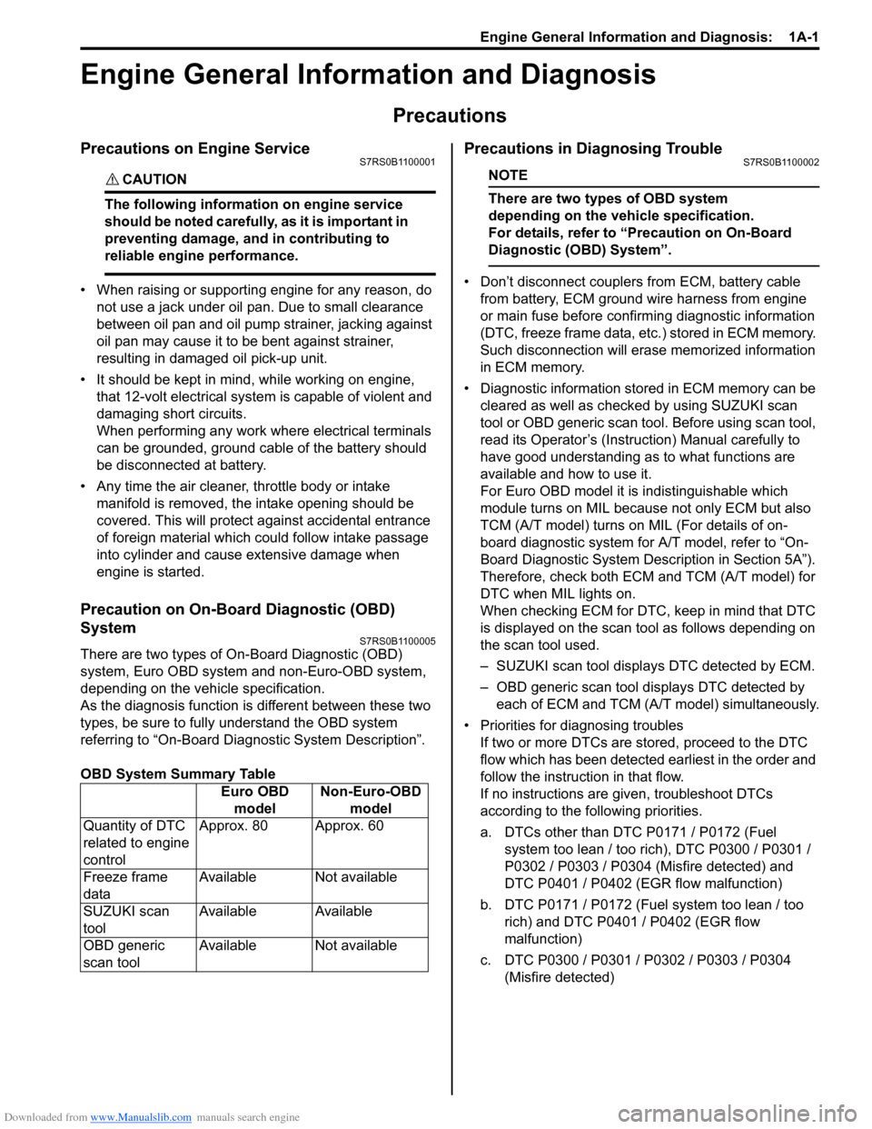
OBD System Summary Table
Precautions in Diagnosing TroubleS7RS0B1100002
NOTE
There are two types of OBD system
depending on the vehicle specification.
For details, refer to “Precaution on On-Board
Diagnostic (OBD) System”.
• Don’t disconnect couplers from ECM, battery cable
from battery, ECM ground wire harness from engine
or main fuse before confirming diagnostic information
(DTC, freeze frame data, etc.) stored in ECM memory.
Such disconnection will erase memorized information
in ECM memory.
• Diagnostic information stored in ECM memory can be cleared as well as checke d by using SUZUKI scan
tool or OBD generic scan tool. Before using scan tool,
read its Operator’s (Instruction) Manual carefully to
have good understanding as to what functions are
available and how to use it.
For Euro OBD model it is indistinguishable which
module turns on MIL because not only ECM but also
TCM (A/T model) turns on MIL (For details of on-
board diagnostic system for A/T model, refer to “On-
Board Diagnostic System Description in Section 5A”).
Therefore, check both ECM and TCM (A/T model) for
DTC when MIL lights on.
When checking ECM for DTC, keep in mind that DTC
is displayed on the scan tool as follows depending on
the scan tool used.
– SUZUKI scan tool displays DTC detected by ECM.
– OBD generic scan tool displays DTC detected by each of ECM and TCM (A/T model) simultaneously.
• Priorities for diagnosing troubles If two or more DTCs are stored, proceed to the DTC
flow which has been detected earliest in the order and
follow the instructi on in that flow.
If no instructions are given, troubleshoot DTCs
according to the following priorities.
a. DTCs other than DTC P0171 / P0172 (Fuel system too lean / too rich), DTC P0300 / P0301 /
P0302 / P0303 / P0304 (Misfire detected) and
DTC P0401 / P0402 (EGR flow malfunction)
b. DTC P0171 / P0172 (Fuel system too lean / too rich) and DTC P0401 / P0402 (EGR flow
malfunction)
c. DTC P0300 / P0301 / P0302 / P0303 / P0304 (Misfire detected)
Euro OBD
model Non-Euro-OBD
model
Quantity of DTC
related to engine
control Approx. 80 Approx. 60
Freeze frame
data Available Not available
SUZUKI scan
tool Available Available
OBD generic
scan tool Available Not available
Page 91 of 1496

Downloaded from www.Manualslib.com manuals search engine Engine General Information and Diagnosis: 1A-41
Engine Symptom DiagnosisS7RS0B1104010
Perform troubleshooting referring to the followings when ECM has detected no DTC and no abnormality has been
found in “Visual Inspection” and “Engine Basic Inspection”.
Condition Possible cause Correction / Reference Item
Hard starting (Engine
cranks OK) Faulty spark plug
“Spark Plug Inspection in Section 1H”
Leaky high-tension cord “High-Tension Cord Inspection in Section 1H”
Loose connection or disconnection of
high-tension cord(s) or lead wire(s) “High-Tension Cord Removal and Installation
in Section 1H”
Faulty ignition coil “Ignition Coil Assembly (Including ignitor)
Inspection in Section 1H”
Dirty or clogged fuel hose or pipe “Fuel Pressure Check”
Malfunctioning fuel pump “Fuel Pressure Check”
Air drawn in through intake manifold
gasket or throttle body gasket
Faulty electric throttle body assembly “Electric Throttle Body Assembly On-Vehicle
Inspection in Section 1C”
Faulty APP sensor assembly “APP Sensor Assembly Inspection in Section
1C”
Faulty ECT sensor or MAF sensor “ECT Sensor Inspection in Section 1C” or
“MAF and IAT Sensor Inspection in Section
1C”
Faulty ECM
Low compression “Compression Check in Section 1D”
Poor spark plug tightening or faulty
gasket “Spark Plug Removal and Installation in
Section 1H”
Compression leak from valve seat “Valves and Valve Guides Inspection in
Section 1D”
Sticky valve stem “Valves and Valve Guides Inspection in
Section 1D”
Weak or damaged valve springs “Valve Spring Inspection in Section 1D”
Compression leak at cylinder head
gasket “Cylinder Head Inspection in Section 1D”
Sticking or damaged piston ring “Cylinders, Pistons and Piston Rings
Inspection in Section 1D”
Worn piston, ring or cylinder “Cylinders, Pistons and Piston Rings
Inspection in Section 1D”
Malfunctioning PCV valve “PCV Valve Inspection in Section 1B”
Camshaft position control (VVT) system
out of order “Oil Control Valve Inspection in Section 1D”
Faulty EGR system “EGR System Inspection in Section 1B”
Low oil pressure Improper oil viscosity “Engine Oil and Filter Change in Section 0B”
Malfunctioning oil pressure switch “Oil Pressure Switch Inspection in Section 9C”
Clogged oil strainer “Oil Pan and Oil Pump Strainer Cleaning in
Section 1E”
Functional deterioration of oil pump “Oil Pump Inspection in Section 1E”
Worn oil pump relief valve “Oil Pump Inspection in Section 1E”
Excessive clearance in various sliding
parts
Engine noise – Valve
noise
NOTE
Before checking
mechanical noise, make
sure that:
• Specified spark plug is used.
• Specified fuel is used.
Improper valve lash “Camshaft, Tappet and Shim Inspection in
Section 1D”
Worn valve stem and guide “Valves and Valve Guides Inspection in
Section 1D”
Weak or broken valve spring “Valve Spring Inspection in Section 1D”
Warped or bent valve “Valves and Valve Guides Inspection in
Section 1D”
Page 306 of 1496

Downloaded from www.Manualslib.com manuals search engine 1D-21 Engine Mechanical:
Timing Chain Cover Removal and InstallationS7RS0B1406013
CAUTION!
• Keep working table, tools and hands clean while overhauling.
• Use special care to handle aluminum parts so as not to damage them.
• Do not expose removed parts to dust. Keep them always clean.
Removal
1) Remove engine assembly from vehicle referring to “Engine Assembly Removal and Installation”.
2) Remove water pump / generator drive belt referring to “Water Pump / Generator Drive Belt Removal and
Installation in Section 1J”.
3) Remove crankshaft pulley bolt. To lock crankshaft pulley (1), use special tool with it
as shown in figure.
Special tool
(A): 09917–68221
4) Remove crankshaft pulley (1). If it is hard to remove, use special tools as shown in
figure.
Special tool
(A): 09944–36011
(B): 09926–58010 5) Remove cylinder head cove
r referring to “Cylinder
Head Cover Removal and Installation”.
6) Remove oil pan referring to “Oil Pan and Oil Pump
Strainer Removal and Inst allation in Section 1E”.
7) Remove water pump pulley.
8) Remove A/C bracket from cylinder block.
9) Remove oil gallery pipe s No.2 (1) and No.3 (2).
10) Remove cap (1) from timing chain cover (2). 11) Remove timing chain cover (2).
12) Remove oil control valve from timing chain cover referring to “Oil Cont rol Valve Removal and
Installation”.
10. Copper washer :30 N⋅m (3.0 kgf-m, 22.0 lb-ft)
11. Oil gallery pipe No.1 bolt : 150 N⋅m (15.0 kgf-m, 108.5 lb-ft)
12. Oil gallery pipe No.2 : Do not reuse.
I2RH0B140051-01
I2RH0B140052-01
1
2
I3RH0B140021-01
1 2
I3RH0B140022-01
Page 308 of 1496

Downloaded from www.Manualslib.com manuals search engine 1D-23 Engine Mechanical:
8) Install new O-ring (1) to oil gallery pipes No.2 (2) and
No.3 (3).
9) Install oil gallery pipes No.2 and No.3 to cylinder
head (4) and timing chain cover (5).
Tighten bolts to specified torque.
Tightening torque
Oil gallery pipe No.2 and No.3 bolt (a): 11 N·m (
1.1 kgf-m, 8.0 lb-ft)
10) Install water pump pulley. 11) Install cylinder head cover referring to “Cylinder Head Cover Removal and Installation”.
12) Install oil pan referring to “Oil Pan and Oil Pump
Strainer Removal and Installation in Section 1E”.
13) Install crankshaft pulley (1). Tighten bolt (2) to specified torque. To lock crankshaft pulley, use
special tool with it as shown in figure.
Special tool
(A): 09917–68221
Tightening torque
Crankshaft pulley bolt (a): 150 N·m (15.0 kgf-m,
108.5 lb-ft)
14) Install engine assembly to vehicle referring to “Engine Assembly Removal and Installation”.
Timing Chain Cover InspectionS7RS0B1406014
Oil Seal
Check oil seal lip for fault or other damage. Replace as
necessary. Timing Chain Cover
Inspect strainer (1) of oil passage for driving intake cam
timing sprocket assembly (VVT actuator).
If clog or foreign matter exists, clean strainer.
Oil Control Valve Removal and InstallationS7RS0B1406015
Removal
Remove oil gallery pipe No.1
(1) and oil control valve (2)
from timing chain cover (3).
Installation
1) Install new O-ring (4) to oil control valve.
2) Install oil control valve to timing chain cover. Tighten nuts to specification.
Tightening torque
Oil control valve mounting nut (a): 11 N·m (1.1
kgf-m, 8.0 lb-ft)
3) Install oil gallery pipe No .1 with new copper washers
(5) to timing chain cover.
Tighten bolts to specification.
Tightening torque
Oil gallery pipe No.1 bolt (b): 30 N·m (3.0 kgf-m,
21.5 lb-ft)
(a)
(a) 1
2
3
4
5
I3RH0B140027-01
I2RH0B140056-01
1
I3RH0B140028-01
1
5
(b) 3
(a)
2 4
5
I3RM0A140027-01
Page 320 of 1496

Downloaded from www.Manualslib.com manuals search engine 1D-35 Engine Mechanical:
Valves and Cylinder Head Removal and
Installation
S7RS0B1406024
Removal1) Remove engine assembly from vehicle referring to “Engine Assembly Removal and Installation”.
2) Remove oil pan referring to “Oil Pan and Oil Pump
Strainer Removal and Installation in Section 1E”.
3) Remove cylinder head cover referring to “Cylinder Head Cover Removal and Installation”.
4) Remove timing chain cover referring to Steps 2) to 11) of “Removal” in “Tim ing Chain Cover Removal
and Installation”.
5) Remove timing chain referring to Steps 2) to 6) of “Removal” in “Timing Chain and Chain Tensioner
Removal and Installation”.
6) Remove intake and exhaust camshafts referring to Steps 3) to 8) of “Removal” in “Camshaft, Tappet and
Shim Removal and Installation”.
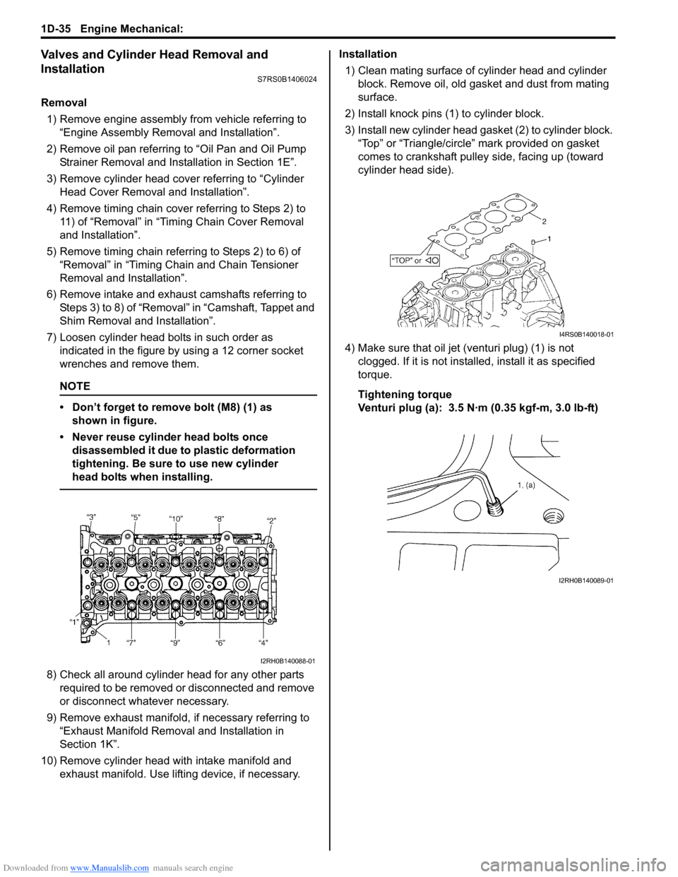
7) Loosen cylinder head bolts in such order as indicated in the figure by using a 12 corner socket
wrenches and remove them.
NOTE
• Don’t forget to remove bolt (M8) (1) as shown in figure.
• Never reuse cylinder head bolts once disassembled it due to plastic deformation
tightening. Be sure to use new cylinder
head bolts when installing.
8) Check all around cylinder head for any other parts required to be removed or disconnected and remove
or disconnect whatever necessary.
9) Remove exhaust manifold, if necessary referring to
“Exhaust Manifold Removal and Installation in
Section 1K”.
10) Remove cylinder head wi th intake manifold and
exhaust manifold. Use lifting device, if necessary. Installation
1) Clean mating surface of cylinder head and cylinder block. Remove oil, old gasket and dust from mating
surface.
2) Install knock pins (1) to cylinder block.
3) Install new cylinder head gasket (2) to cylinder block. “Top” or “Triangle/circle” mark provided on gasket
comes to crankshaft pulley side, facing up (toward
cylinder head side).
4) Make sure that oil jet (venturi plug) (1) is not clogged. If it is not install ed, install it as specified
torque.
Tightening torque
Venturi plug (a): 3.5 N·m (0.35 kgf-m, 3.0 lb-ft)
I2RH0B140088-01
I4RS0B140018-01
I2RH0B140089-01
Page 321 of 1496

Downloaded from www.Manualslib.com manuals search engine Engine Mechanical: 1D-36
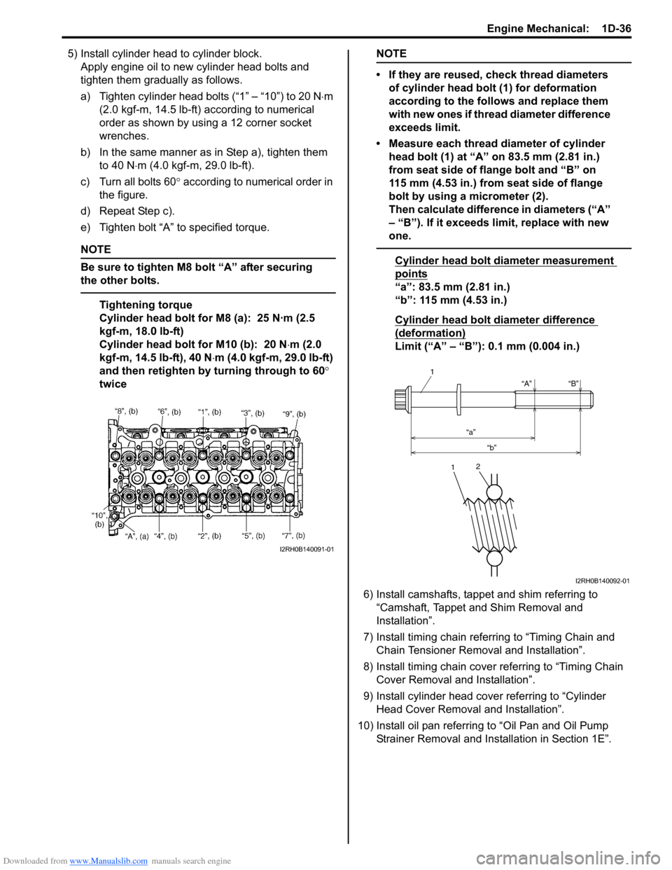
5) Install cylinder head to cylinder block.Apply engine oil to new cylinder head bolts and
tighten them gradually as follows.
a) Tighten cylinder head bolts (“1” – “10”) to 20 N ⋅m
(2.0 kgf-m, 14.5 lb-ft) according to numerical
order as shown by using a 12 corner socket
wrenches.
b) In the same manner as in Step a), tighten them to 40 N ⋅m (4.0 kgf-m, 29.0 lb-ft).
c) Turn all bolts 60 ° according to numerical order in
the figure.
d) Repeat Step c).
e) Tighten bolt “A” to specified torque.
NOTE
Be sure to tighten M8 bolt “A” after securing
the other bolts.
Tightening torque
Cylinder head bolt for M8 (a): 25 N·m (2.5
kgf-m, 18.0 lb-ft)
Cylinder head bolt for M10 (b): 20 N ⋅m (2.0
kgf-m, 14.5 lb-ft), 40 N ⋅m (4.0 kgf-m, 29.0 lb-ft)
and then retighten by turning through to 60 °
twice
NOTE
• If they are reused, check thread diameters of cylinder head bolt (1) for deformation
according to the follows and replace them
with new ones if thread diameter difference
exceeds limit.
• Measure each thread diameter of cylinder head bolt (1) at “A” on 83.5 mm (2.81 in.)
from seat side of flange bolt and “B” on
115 mm (4.53 in.) from seat side of flange
bolt by using a micrometer (2).
Then calculate difference in diameters (“A”
– “B”). If it exceeds limit, replace with new
one.
Cylinder head bolt diameter measurement
points
“a”: 83.5 mm (2.81 in.)
“b”: 115 mm (4.53 in.)
Cylinder head bolt diameter difference
(deformation)
Limit (“A” – “B”): 0.1 mm (0.004 in.)
6) Install camshafts, tappet and shim referring to “Camshaft, Tappet and Shim Removal and
Installation”.
7) Install timing chain referring to “Timing Chain and Chain Tensioner Remova l and Installation”.
8) Install timing chain cover referring to “Timing Chain Cover Removal and Installation”.
9) Install cylinder head cover referring to “Cylinder Head Cover Removal and Installation”.
10) Install oil pan referring to “Oil Pan and Oil Pump
Strainer Removal and Inst allation in Section 1E”.
I2RH0B140091-01
“A”
“a” “b” “B”
1
1
2
I2RH0B140092-01
Page 342 of 1496

Downloaded from www.Manualslib.com manuals search engine 1D-57 Engine Mechanical:
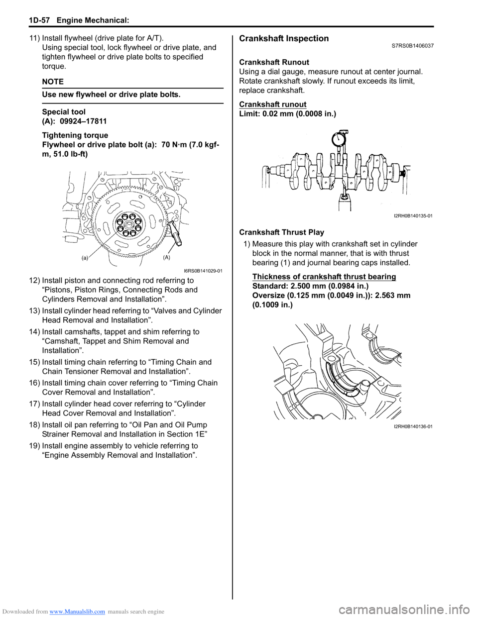
11) Install flywheel (drive plate for A/T).Using special tool, lock flyw heel or drive plate, and
tighten flywheel or drive plate bolts to specified
torque.
NOTE
Use new flywheel or drive plate bolts.
Special tool
(A): 09924–17811
Tightening torque
Flywheel or drive plate bolt (a): 70 N·m (7.0 kgf-
m, 51.0 lb-ft)
12) Install piston and connecting rod referring to “Pistons, Piston Rings, Connecting Rods and
Cylinders Removal and Installation”.
13) Install cylinder head referring to “Valves and Cylinder Head Removal and Installation”.
14) Install camshafts, tappet and shim referring to “Camshaft, Tappet and Shim Removal and
Installation”.
15) Install timing chain referring to “Timing Chain and Chain Tensioner Removal and Installation”.
16) Install timing chain cover referring to “Timing Chain Cover Removal and Installation”.
17) Install cylinder head cover referring to “Cylinder Head Cover Removal and Installation”.
18) Install oil pan referring to “Oil Pan and Oil Pump
Strainer Removal and Installation in Section 1E”
19) Install engine assembly to vehicle referring to “Engine Assembly Removal and Installation”.
Crankshaft InspectionS7RS0B1406037
Crankshaft Runout
Using a dial gauge, measure runout at center journal.
Rotate crankshaft slowly. If runout exceeds its limit,
replace crankshaft.
Crankshaft runout
Limit: 0.02 mm (0.0008 in.)
Crankshaft Thrust Play
1) Measure this play with crankshaft set in cylinder block in the normal manner, that is with thrust
bearing (1) and journal bearing caps installed.
Thickness of crankshaft thrust bearing
Standard: 2.500 mm (0.0984 in.)
Oversize (0.125 mm (0.0049 in.)): 2.563 mm
(0.1009 in.)
I6RS0B141029-01
I2RH0B140135-01
I2RH0B140136-01