2007 SUZUKI GRAND VITARA ECU
[x] Cancel search: ECUPage 57 of 211

Downloaded from www.Manualslib.com manuals search engine 2-43 BEFORE DRIVING
66J21-03E
bag will not deploy and the seat belt pre-
tensioner will not operate.
If you have secured a child in the front pas-
senger seat in a forward-facing child
restraint system or booster seat and the
“PASS AIR BAG OFF” indicator light is not
on, turn the vehicle off, remove the child
restraint or booster seat from the vehicle
and reinstall it following the child restraint
or booster seat manufacturer’s directions.
Also refer to “Seat Belts and Child
Restraint Systems” in this section. If, after
reinstalling the child restraint and restart-
ing the vehicle, the “PASS AIR BAG OFF”
indicator is still not lit, check to make sure
that the vehicle’s seatback is not pressing
the child restraint into the seat cushion. If
this happens, slightly recline the vehicle’s
seatback and adjust the seat cushion if
possible. Also make sure the child restraint
is not trapped under the vehicle head
restraint. If this happens, adjust the head
restraint. If the “PASS AIR BAG OFF” indi-
cator is still not on, secure the child in the
child restraint or booster seat in a rear seat
position in the vehicle and check with your
dealer.
65D607
According to accident statistics, children
are safer when properly restrained in rear
seating positions than in front seating posi-
tions. Whenever possible, SUZUKI recom-
mends you install child restraints in the
rear seat.
The front passenger sensing system is
designed to enable the front passenger’sfront air bag when the system senses a
properly-seated adult in the front passen-
ger’s seat. When the passenger sensing
system has allowed the air bag to be
enabled, the “PASS AIR BAG OFF” indica-
tor will remain off to remind you that the air
bag is active.
If a person of adult size is sitting in the
front passenger’s seat and the “PASS AIR
BAG OFF” indicator comes on, it could be
because that person isn’t sitting properly in
the seat. If this happens, unfasten the seat
belts, sit upright in the center of the seat
with the seatback nearly vertical and your
legs outstretched, and refasten the seat
belt.
52D258
When seated as shown in the above illus-
tration, the front passenger sensing sys-
tem senses a properly-seated occupant
and enables the air bag.
WARNING
Do not install a rear-facing child
restraint in the front passenger’s
seat. If the passenger’s front air bag
inflates, a child in a rear-facing child
restraint could be seriously injured.
The back of a rear-facing child
restraint would be too close to the
inflating air bag.
Supplemental Restraint System (air bags): 3, 9, 12
Page 79 of 211
Downloaded from www.Manualslib.com manuals search engine 4-17 INSTRUMENT PANEL
66J21-03E
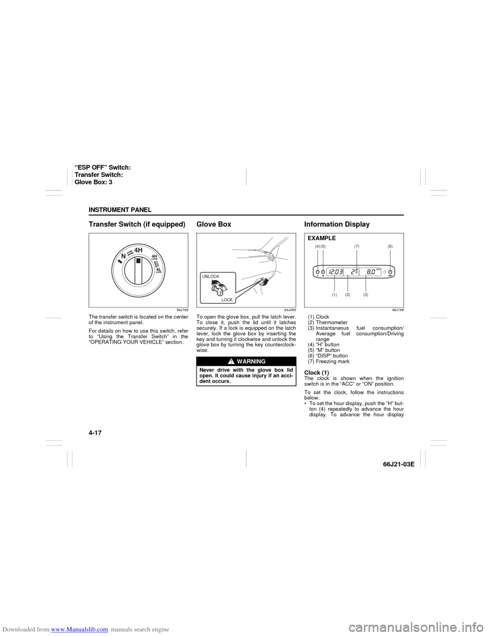
Transfer Switch (if equipped)
66J168
The transfer switch is located on the center
of the instrument panel.
For details on how to use this switch, refer
to “Using the Transfer Switch” in the
“OPERATING YOUR VEHICLE” section.
Glove Box
64J065
To open the glove box, pull the latch lever.
To close it, push the lid until it latches
securely. If a lock is equipped on the latch
lever, lock the glove box by inserting the
key and turning it clockwise and unlock the
glove box by turning the key counterclock-
wise.
Information Display
66J198
(1) Clock
(2) Thermometer
(3) Instantaneous fuel consumption/
Average fuel consumption/Driving
range
(4) “H” button
(5) “M” button
(6) “DISP” button
(7) Freezing markClock (1)The clock is shown when the ignition
switch is in the “ACC” or “ON” position.
To set the clock, follow the instructions
below.
To set the hour display, push the “H” but-
ton (4) repeatedly to advance the hour
display. To advance the hour display
WARNING
Never drive with the glove box lid
open. It could cause injury if an acci-
dent occurs.UNLOCK
LOCK
(4)
(2)
(1)
(3)
(5)
(6)
(7)
EXAMPLE
“ESP OFF” Switch:
Transfer Switch:
Glove Box: 3
Page 82 of 211
Downloaded from www.Manualslib.com manuals search engine 4-20 INSTRUMENT PANEL
66J21-03E
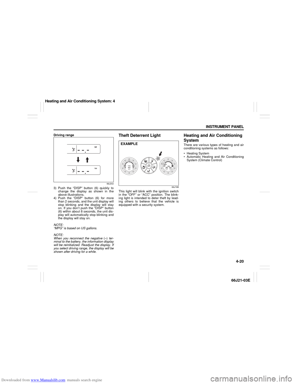
Driving range
66J202
3) Push the “DISP” button (6) quickly to
change the display as shown in the
above illustrations.
4) Push the “DISP” button (6) for more
than 2 seconds, and the unit display will
stop blinking and the display will stay
on. If you don’t push the “DISP” button
(6) within about 8 seconds, the unit dis-
play will automatically stop blinking and
the display will stay on.
NOTE:
“MPG” is based on US gallons.
NOTE:
When you reconnect the negative (–) ter-
minal to the battery, the information display
will be reinitialized. Readjust the display. If
you select driving range, the display will be
shown after driving for a while.
Theft Deterrent Light
66J188
This light will blink with the ignition switch
in the “OFF” or “ACC” position. The blink-
ing light is intended to deter theft by lead-
ing others to believe that the vehicle is
equipped with a security system.
Heating and Air Conditioning
SystemThere are various types of heating and air
conditioning systems as follows:
Heating System
Automatic Heating and Air Conditioning
System (Climate Control)
EXAMPLE
Heating and Air Conditioning System: 4
Page 127 of 211
Downloaded from www.Manualslib.com manuals search engine 8-1 VEHICLE LOADING AND TOWING
66J21-03E
Vehicle Loading
54G307
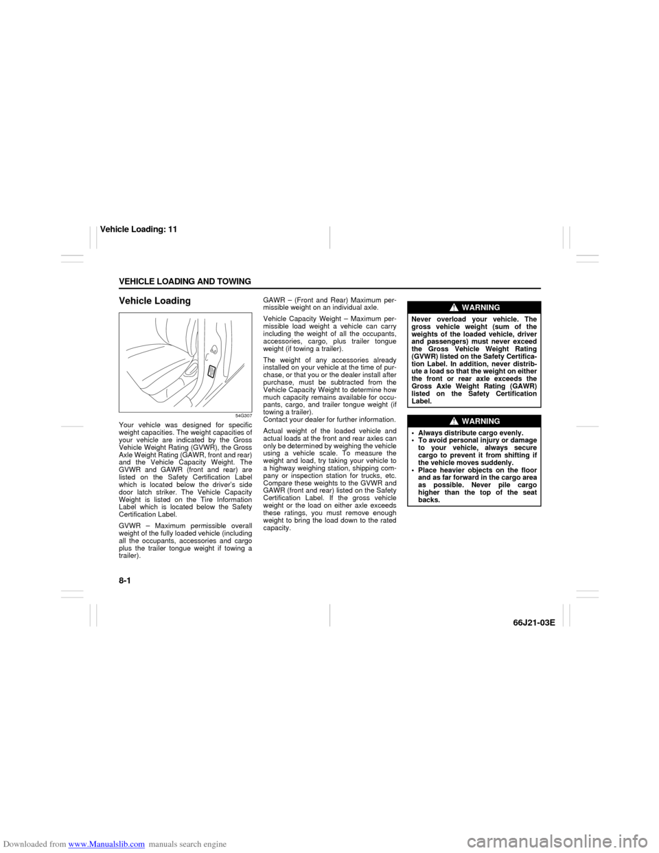
Your vehicle was designed for specific
weight capacities. The weight capacities of
your vehicle are indicated by the Gross
Vehicle Weight Rating (GVWR), the Gross
Axle Weight Rating (GAWR, front and rear)
and the Vehicle Capacity Weight. The
GVWR and GAWR (front and rear) are
listed on the Safety Certification Label
which is located below the driver’s side
door latch striker. The Vehicle Capacity
Weight is listed on the Tire Information
Label which is located below the Safety
Certification Label.
GVWR – Maximum permissible overall
weight of the fully loaded vehicle (including
all the occupants, accessories and cargo
plus the trailer tongue weight if towing a
trailer).GAWR – (Front and Rear) Maximum per-
missible weight on an individual axle.
Vehicle Capacity Weight – Maximum per-
missible load weight a vehicle can carry
including the weight of all the occupants,
accessories, cargo, plus trailer tongue
weight (if towing a trailer).
The weight of any accessories already
installed on your vehicle at the time of pur-
chase, or that you or the dealer install after
purchase, must be subtracted from the
Vehicle Capacity Weight to determine how
much capacity remains available for occu-
pants, cargo, and trailer tongue weight (if
towing a trailer).
Contact your dealer for further information.
Actual weight of the loaded vehicle and
actual loads at the front and rear axles can
only be determined by weighing the vehicle
using a vehicle scale. To measure the
weight and load, try taking your vehicle to
a highway weighing station, shipping com-
pany or inspection station for trucks, etc.
Compare these weights to the GVWR and
GAWR (front and rear) listed on the Safety
Certification Label. If the gross vehicle
weight or the load on either axle exceeds
these ratings, you must remove enough
weight to bring the load down to the rated
capacity.
WARNING
Never overload your vehicle. The
gross vehicle weight (sum of the
weights of the loaded vehicle, driver
and passengers) must never exceed
the Gross Vehicle Weight Rating
(GVWR) listed on the Safety Certifica-
tion Label. In addition, never distrib-
ute a load so that the weight on either
the front or rear axle exceeds the
Gross Axle Weight Rating (GAWR)
listed on the Safety Certification
Label.
WARNING
Always distribute cargo evenly.
To avoid personal injury or damage
to your vehicle, always secure
cargo to prevent it from shifting if
the vehicle moves suddenly.
Place heavier objects on the floor
and as far forward in the cargo area
as possible. Never pile cargo
higher than the top of the seat
backs.
Vehicle Loading: 11
Page 128 of 211

Downloaded from www.Manualslib.com manuals search engine 8-2 VEHICLE LOADING AND TOWING
66J21-03E
Trailer TowingYou can use your SUZUKI to tow a trailer,
but you should always observe the require-
ments and recommendations in this sec-
tion. If you intend to tow a trailer, it is
essential to select a trailer and trailer tow-
ing equipment which are compatible. A
reputable trailer dealer can help you.
For Automatic transmission vehicles, shift
into “3” (Low 2) or “L” (Low 1) (if necessary)
and frequently monitor the coolant temper-
ature gauge when towing up a steep hill. If
the gauge indicates overheating, park the
vehicle in a safe place and let the enginecool down. Refer to “If the Engine Over-
heats” section for details on how to deal
with overheating.
HitchesUse only a trailer hitch bracket that is
designed to bolt to the frame of your vehi-
cle, and a hitch that is designed to bolt to
this bracket. We recommend that you use
a genuine SUZUKI trailer hitch bracket and
trailer hitch (available as options), or equiv-
alent.Safety ChainsAlways attach safety chains between your
vehicle and trailer. Cross safety chains
under the tongue of the trailer so that the
tongue will not drop to the road if the trailer
becomes separated from the hitch. Follow
the manufacturer’s recommendation for
attaching safety chains. Always leave just
enough slack to permit full turning. Never
allow safety chains to drag on the road.
Trailer LightsMake sure your trailer is equipped with
lights which meet federal, state and local
requirements. Always check for the proper
operation of all trailer lights before you
start to tow.Brakes CAUTION
Trailer towing puts additional stress
on the engine, drive train and brakes
of your vehicle. Never tow a trailer
during the first 960 km (600 miles) of
vehicle operation.
CAUTION
Because towing a trailer puts addi-
tional stress on your vehicle, more
frequent maintenance will be
required than under normal driving
conditions. Follow the schedule for
Maintenance Recommended Under
Severe Driving Conditions or perform
more frequent maintenance as nec-
essary.
CAUTION
Towing in “D” range up a steep hill
can cause coolant overheating which
may result in engine/automatic trans-
mission damage.
WARNING
Never use a bumper hitch or a hitch
which attaches to the axle of your
vehicle.
WARNING
Never attach safety chains to the
bumper of your vehicle. Secure con-
nections so that they can’t come
loose.
WARNING
Never splice trailer lights directly into
your vehicle’s electrical system, or
electrical system damage may occur.
WARNING
If trailer brakes are used, you should
follow all instructions provided by the
manufacturer. Never tap into the
brake system of your vehicle.
Trailer Towing: 5, 11, 13
Page 136 of 211
Downloaded from www.Manualslib.com manuals search engine 8-10 VEHICLE LOADING AND TOWING
66J21-03E
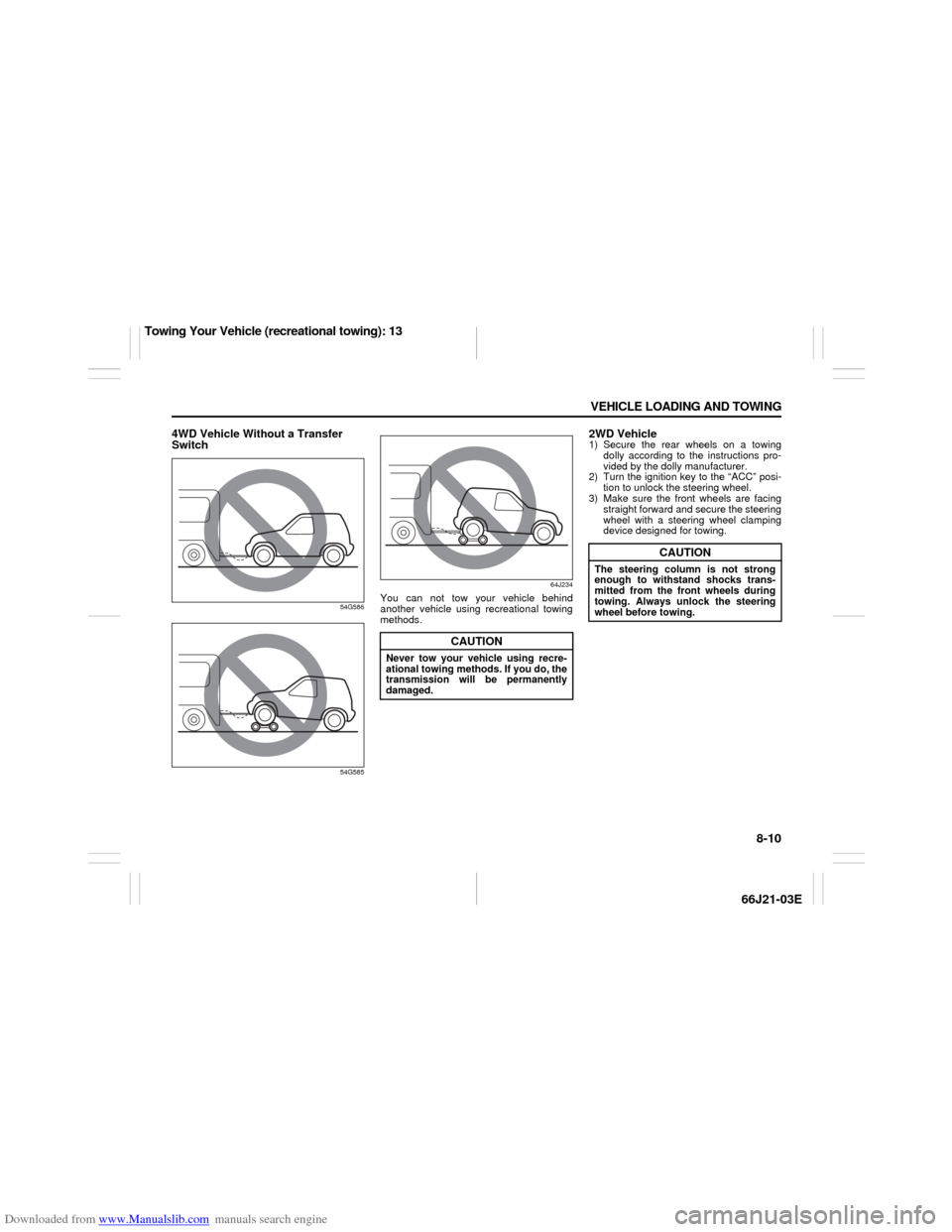
4WD Vehicle Without a Transfer
Switch
54G586
54G58564J234
You can not tow your vehicle behind
another vehicle using recreational towing
methods.
2WD Vehicle1) Secure the rear wheels on a towing
dolly according to the instructions pro-
vided by the dolly manufacturer.
2) Turn the ignition key to the “ACC” posi-
tion to unlock the steering wheel.
3) Make sure the front wheels are facing
straight forward and secure the steering
wheel with a steering wheel clamping
device designed for towing.
CAUTION
Never tow your vehicle using recre-
ational towing methods. If you do, the
transmission will be permanently
damaged.
CAUTION
The steering column is not strong
enough to withstand shocks trans-
mitted from the front wheels during
towing. Always unlock the steering
wheel before towing.
Towing Your Vehicle (recreational towing): 13
Page 154 of 211
Downloaded from www.Manualslib.com manuals search engine 9-16 INSPECTION AND MAINTENANCE
66J21-03E
NOTE:
Do not check the fluid level if you have just
driven the vehicle for a long time at high
speed, if you have driven in city traffic in
hot weather, or if the vehicle has been pull-
ing a trailer. Wait until the fluid cools down
(about 30 minutes), or the fluid level indica-
tion will not be correct.
3) Park your vehicle on level ground.
4) Apply the parking brake and then start
the engine in “P” (Park). Let it idle for
two minutes and keep it running during
the fluid level check.
5) With your foot on the brake pedal, move
the gearshift lever through each gear,
pausing for about three seconds in
each range. Then move it back to the
“P” (Park) position.
52D032
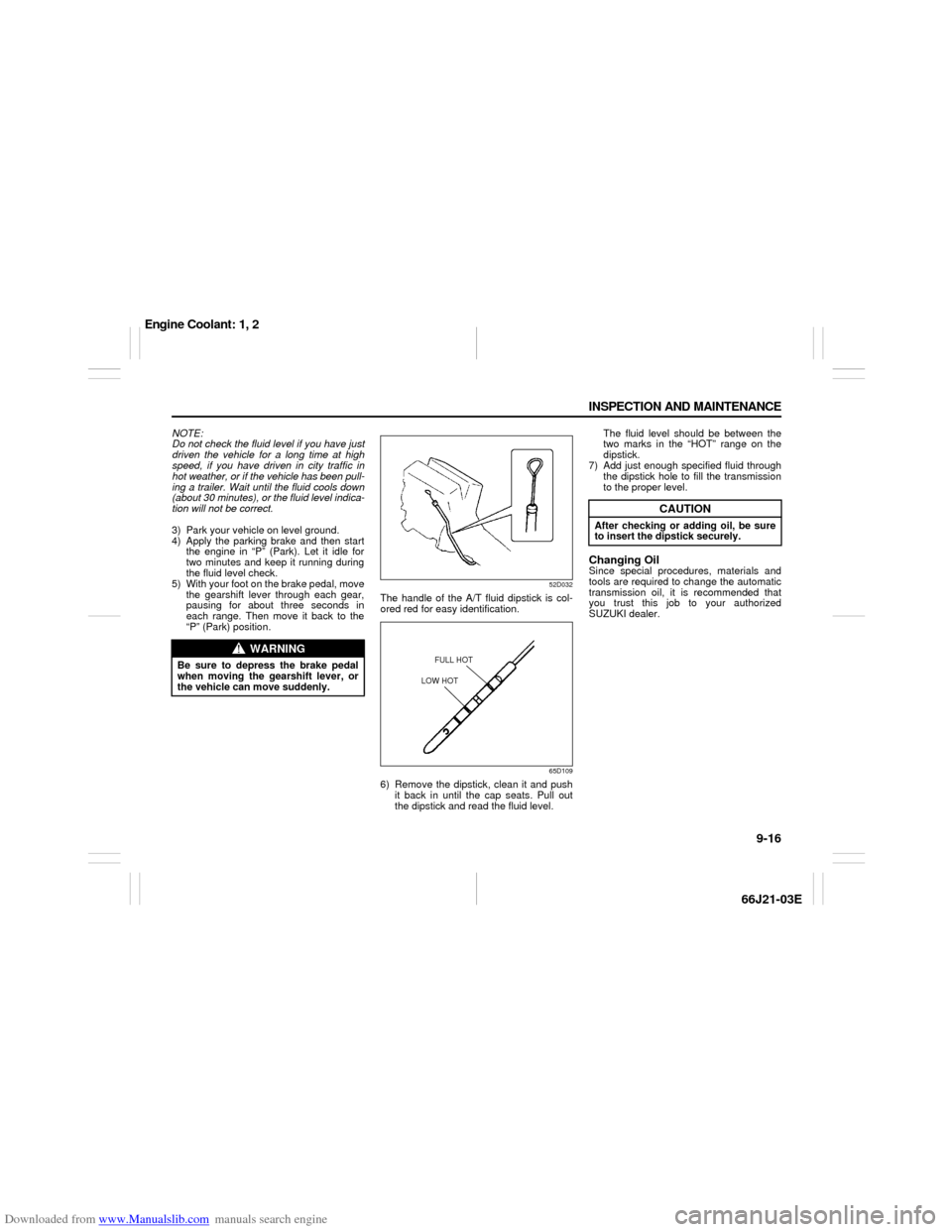
The handle of the A/T fluid dipstick is col-
ored red for easy identification.
65D109
6) Remove the dipstick, clean it and push
it back in until the cap seats. Pull out
the dipstick and read the fluid level. The fluid level should be between the
two marks in the “HOT” range on the
dipstick.
7) Add just enough specified fluid through
the dipstick hole to fill the transmission
to the proper level.
Changing OilSince special procedures, materials and
tools are required to change the automatic
transmission oil, it is recommended that
you trust this job to your authorized
SUZUKI dealer.
WARNING
Be sure to depress the brake pedal
when moving the gearshift lever, or
the vehicle can move suddenly.
FULL HOT
LOW HOT
CAUTION
After checking or adding oil, be sure
to insert the dipstick securely.
Engine Coolant: 1, 2
Page 161 of 211

Downloaded from www.Manualslib.com manuals search engine 9-23 INSPECTION AND MAINTENANCE
66J21-03E
60G104
Parking Brake Lever
60A226
Check the parking brake for proper adjust-
ment by counting the number of clicks
made by the ratchet teeth as you slowly
pull up on the parking brake lever to the
point of full engagement. The parking
brake lever should stop between the speci-
fied ratchet teeth and the rear wheels
should be securely locked. If the parking
brake is not properly adjusted or the
brakes drag after the lever has been fully
released, have the parking brake inspected
and/or adjusted by your SUZUKI dealer.
Steering Wheel
54G110
Check the play of the steering wheel by
gently turning it from left to right and mea-
suring the distance that it moves before
you feel slight resistance. The play should
be between the specified values. Check
that the steering wheel turns easily and
smoothly without rattling by turning it all the
way to the right and to the left while driving
very slowly in an open area. If the amount
of free play is outside the specification or
you find anything else to be wrong, an
inspection must be performed by your
SUZUKI dealer.
WARNING
If you experience any of the following
problems with your vehicle’s brake
system, have the vehicle inspected
immediately by your SUZUKI dealer.
Poor braking performance
Uneven braking (Brakes not work-
ing uniformly on all wheels.)
Excessive pedal travel
Brake dragging
Excessive noise
(Except ABS equipped vehicle)
Pedal pulsation (Pedal pulsates
when pressed for braking.)
Ratchet tooth specification “b”
5th – 7th
200 N (44 lbs, 20 kg)
“b”
EXAMPLE
Steering wheel play “c”
0 – 30 mm (0.0 – 1.2 in.)EXAMPLE
Tires: 6