Page 185 of 232

Downloaded from www.Manualslib.com manuals search engine 9-32 INSPECTION AND MAINTENANCE
54G27-03E
GLOSSARY OF TIRE TERMINOL-
OGYAccessory Weight – the combined weight
(in excess of those standard items which
may be replaced) of automatic transaxle,
power steering, power brakes, power win-
dows, power seats, radio, and heater, to
the extent that these items are available as
factory-installed equipment (whether
installed or not).
Cold Tire Inflation Pressure – the pressure
in a tire that has been driven less than 1
mile or has been standing for three hours
or more.
Curb Weight – the weight of a motor vehi-
cle with standard equipment including the
maximum capacity of fuel, oil, and coolant,
and, if so equipped, air conditioning and
additional weight optional engine.
Intended Outboard Sidewall – (1) the side-
wall that contains a whitewall, bears white
lettering or bears manufacturer, brand,
and/or model name molding that is higher
or deeper than the same molding on the
other sidewall of the tire, or (2) the outward
facing sidewall of an asymmetrical tire that
has a particular side that must always face
outward when mounted on a vehicle.
Maximum Inflation Pressure – the maxi-
mum cold inflation pressure a tire is
designed to support in normal service.
Maximum Loaded Vehicle Weight – the
sum of curb weight, accessory weight,vehicle capacity weight (total load capac-
ity), and production options weight.
Normal Occupant Weight – 68 kilograms
times the number of occupants specified in
the second column of Table 1 (shown
below).
Occupant distribution – distribution of
occupants in a vehicle as specified in the
third column of Table 1 (shown below).
Production Options Weight – the combined
weight of those installed regular production
options weighing over 2.3 kilograms in
excess of those standard items which they
replace, not previously considered in curb
weight or accessory weight, including
heavy duty brakes, ride levelers, roof rack,
heavy duty battery, and special trim.
Recommended Inflation Pressure – the
cold tire inflation pressure recommended
by a manufacturer.
Rim – metal support for a tire or tire and
tube assembly upon which the tire beads
are seated.
Vehicle Capacity Weight – the rated cargo
and luggage load plus 68 kilograms (150
lbs) times the vehicle’s designated seating
capacity.
Vehicle Maximum Load on the Tire – the
load on an individual tire that is determined
by distributing to each axle its share of the
maximum loaded vehicle weight and divid-
ing by two.Vehicle Normal Load on the Tire – the load
on an individual tire that is determined by
distributing to each axle its share of the
curb weight, accessory weight, and normal
occupant weight (distributed in accordance
with Table 1 shown below) and dividing by
2.
TABLE 1 – Occupant Loading and Dis-
tribution For Vehicle Normal Load For
Various Designated Seating Capacities
Vehicle LoadingYour vehicle was designed for specific
load capacities. The load capacities of
your vehicle are indicated by the Gross
Vehicle Weight Rating (GVWR), the Gross
Axle Weight Rating (GAWR, front and
rear), and the total load capacity, the seat-
ing capacity, and the cargo load capacity.
The GVWR and GAWR (front and rear) are
listed on the Safety Certification Label
which is located below the driver’s side
door latch striker. The total load capacity
and seating capacity are listed on the Tire
and Loading Information Label which is
located below the Safety CertificationDesignated
seating capac-
ity, number of
occupantsVehicle normal
load, number
of occupantsOccupant
distribution in
a normally
loaded vehicle
2 through 4 2 2 in front
5 through 10 32 in front, 1 in
second seat
Fuses: 7
Page 186 of 232

Downloaded from www.Manualslib.com manuals search engine 9-33 INSPECTION AND MAINTENANCE
54G27-03E
Label. The cargo load capacity can be
determined as described below.
Cargo Load Capacity – Maximum weight
of cargo and luggage that the vehicle can
safely carry. Cargo load capacity is the dif-
ference between the total load capacity of
the vehicle and the total combined weight
of all vehicle occupants. Refer to “Steps for
Determining Correct Load Limit” for details
on how to determine cargo load capacity.
GVWR – Maximum permissible overall
weight of the fully loaded vehicle (including
all the occupants, accessories and cargo
plus the trailer tongue weight if towing a
trailer).
GAWR – (Front and Rear) Maximum per-
missible weight on an individual axle.
Seating Capacity – Maximum number of
occupants the vehicle is designed to carry.
NOTE:
Even though the number of occupants is
within the seating capacity, you still must
make sure that you do not exceed the total
load capacity of the vehicle.
Total Load Capacity – Maximum permissi-
ble weight a vehicle can carry including the
weight of all the occupants, accessories,
cargo, plus trailer tongue weight (if towing
a trailer).
The weight of any accessories already
installed on your vehicle at the time of pur-chase, or that you or the dealer install after
purchase, must be subtracted from the
total load capacity to determine how much
capacity remains available for occupants,
cargo, and trailer tongue weight (if towing
a trailer). Contact your dealer for further
information.
Actual weight of the loaded vehicle and
actual loads at the front and rear axles can
only be determined by weighing the vehi-
cle using a vehicle scale. To measure the
weight and load, try making your vehicle to
a highway weighing station, shipping com-
pany or inspection station for trucks, etc.
Compare these weights to the GVWR and
GAWR (front and rear) listed on the Safety
Certification Label. If the gross vehicle
weight or the load on either axle exceeds
these ratings, you must remove enough
weight to bring the load down to the rated
capacity.
WARNING
Never overload your vehicle. Over-
loading your vehicle can cause dam-
age to your tires and lead to poor
steering and braking which can result
in an accident. The gross vehicle
weight (sum of the weights of the
loaded vehicle, driver and passen-
gers) must never exceed the Gross
Vehicle Weight Rating (GVWR) listed
on the Safety Certification Label. In
addition, never distribute a load so
that the weight on either the front or
rear axle exceeds the Gross Axle
Weight Rating (GAWR) listed on the
Safety Certification Label.
WARNING
Always distribute cargo evenly.
To avoid personal injury or damage
to your vehicle, always secure
cargo to prevent it from shifting if
the vehicle moves suddenly.
Place heavier objects on the floor
and as far forward in the cargo area
as possible. Never pile cargo
higher than the top of the seat-
backs.
Fuses: 7
Page 187 of 232
 Locate the statement “The combined
weight of occupants")
Downloaded from www.Manualslib.com manuals search engine 9-34 INSPECTION AND MAINTENANCE
54G27-03E
Steps for Determining Correct Load
Limit
1) Locate the statement “The combined
weight of occupants and cargo should
never exceed XXX kg or XXX lbs” on
your vehicle’s placard.
2) Determine the combined weight of the
driver and passengers that will be riding
in your vehicle.
3) Subtract the combined weight of the
driver and passengers from XXX kg or
XXX lbs.
4) The resulting figure equals the avail-
able amount of cargo and luggage load
capacity. For example, if the “XXX”
amount equals 1400 lbs and there will
be five 150 lb passengers in your vehi-
cle, the amount of available cargo and
luggage load capacity is 650 lbs (1400
– 750 (5 x 150) = 650 lbs).
5) Determine the combined weight of lug-
gage and cargo being loaded on the
vehicle. That weight may not safely
exceed the available cargo and lug-
gage load capacity calculated in Step 4.
6) If your vehicle will be towing a trailer,
load from your trailer will be transferred
to your vehicle. Consult this manual to
determine how this reduces the avail-
able cargo and luggage load capacity
of your vehicle.
Vehicle Loading Example
As an example, suppose that the Tire and
Loading Information label on your vehicle
indicates that your vehicle’s total loadcapacity is 950 lbs. If you were to drive
your vehicle with one passenger, and the
total combined weight of you and your pas-
senger was 350 lbs, then the cargo and
luggage capacity of your vehicle would be
600 lbs (950 – 350 = 600 lbs).
If you later added 2 more passengers, hav-
ing a combined weight of 325 lbs, the
cargo and luggage capacity of your vehicle
would be reduced from 600 lbs to 275 lbs
(600 – 325 = 275 lbs). As you can see, as
the number and combined weight of vehi-
cle occupants increase, the vehicle’s cargo
and luggage capacity decreases.
Suppose again, that you were to take a trip
in your vehicle with the same three pas-
sengers described above, and you
decided to tow a trailer having a trailer
tongue weight of 75 lbs. The cargo and
luggage capacity would be reduced again,
to 200 lbs (275 – 75 = 200 lbs).
Determining Compatibility of Tire and
Vehicle Load Limits
The tires on your vehicle, when they are
inflated to the recommended tire inflation
pressure, have a load-carrying capacity
that is greater than the load that will be on
the tires when the vehicle is at its GVWR
or GAWR limit. Never use replacement
tires that have a load-carrying capacity
less than the original tires on your vehicle.
Tire load-carrying capacity information is
molded into the tire sidewall typically
shown as “Max. Load”. Use of replacement
tires with a lower load-carrying capacitythan the original tires, or failure to keep the
tires inflated to recommended tire pres-
sure, may reduce the GVWR or GAWR
limit of your vehicle.
NOTE:
Use of replacement tires with a higher
load-carrying capacity than the original
tires, or using a tire inflation pressure
higher than the recommended tire inflation
pressure, will not increase the GVWR or
GAWR limit of your vehicle.
Headlight Aiming:
Bulb Replacement: 7
Page 188 of 232

Downloaded from www.Manualslib.com manuals search engine 9-35 INSPECTION AND MAINTENANCE
54G27-03E
Battery
60A269
Your vehicle is equipped with a battery that
requires infrequent maintenance. You will
never have to add water. You should, how-
ever, periodically check the battery, battery
terminals and battery hold-down bracket
for corrosion. Remove corrosion using a
stiff brush and ammonia mixed with water,
or baking soda mixed with water. After
removing corrosion, rinse with clean water.
The test indicator on the top of the battery
provides information on the condition of
the battery.
If your vehicle is not going to be driven for
a month or longer, disconnect the cable
from the negative terminal of the battery to
help prevent discharge.
FusesYour vehicle has three types of fuses, as
described below:
Main Fuse – The main fuse takes current
directly from the battery.
Primary Fuses – These fuses are between
the main fuse and individual fuses, and are
for electrical load groups.
Individual Fuses – These fuses are for
individual electrical circuits.
For details on protected circuits, refer to
the “Fuses and Protected Circuits” section
in this manual.
WARNING
Batteries produce flammable hydro-
gen gas. Keep flames and sparks
away from the battery or an explo-
sion may occur. Never smoke when
working near the battery.
WARNING
When checking or servicing the bat-
tery, disconnect the negative cable.
Be careful not to cause a short circuit
by allowing metal objects to contact
the battery posts and the vehicle at
the same time.EXAMPLE
WARNING
To avoid harm to yourself or damage
to your vehicle or battery, follow the
jump starting instructions in the
“EMERGENCY SERVICE” section of
this manual if it is necessary to jump
start your vehicle.
WARNING
Battery posts, terminals and related
accessories contain lead and lead
compounds. Wash hands after han-
dling.
Bulb Replacement: 7
Page 189 of 232
 Main fuse
(2) Heater fuse
(3) ABS fuse (if equipped)
(4) P")
Downloaded from www.Manualslib.com manuals search engine 9-36 INSPECTION AND MAINTENANCE
54G27-03E
Fuses in the Engine Compartment
54G119
(1) Main fuse
(2) Heater fuse
(3) ABS fuse (if equipped)
(4) Primary fuse
(5) Primary fuse
(6) Brake light fuse
(7) Fuel injection system fuse
(8) A/C fuse (if equipped)
(9) Radiator fan motor fuse
(10) Head light fuse (L)
(11) Head light fuse (R)
The main fuse, primary fuses and some of
the individual fuses are located in the
engine compartment. If the main fuse
blows, no electrical component will func-
tion. If a primary fuse or an individual fuse
blows, no electrical component in the cor-
responding load group will function. When
replacing the main fuse, a primary fuse oran individual fuse, use a genuine SUZUKI
replacement.
60A243
Fuses under the Dash Board
54G120
15A
15A
60A 60A
60A
30A
80A 30A
20A
15A
15A
(2) (6)
(7)(8)(9)(10)(11)
(1) (3)(4)
(5)
30A
15A
15A
USE THE DESIGNATED FUSES AND
RELAYS ONLY.
WARNING
If the main fuse or a primary fuse
blows, be sure to have your vehicle
inspected by an authorized SUZUKI
dealer. Always use a genuine SUZUKI
replacement. Never use a substitute
such as a wire even for a temporary
fix, or extensive electrical damage
and a fire can result.
BLOWNOK
30A
For power window
Bulb Replacement: 7
Page 190 of 232
Downloaded from www.Manualslib.com manuals search engine 9-37 INSPECTION AND MAINTENANCE
54G27-03E
54G256
(1) Fuse puller
The fuses are also located under the
driver’s side of the dashboard. Remove the
fuse box lid by pulling it off. To remove a
fuse, use the fuse puller provided in the
fuse box.
The fuse information is detailed in “FUSES
AND PROTECTED CIRCUITS” section.
65D046
NOTE:
Make sure that the fuse box always carries
spare fuses.
Headlight AimingSince special procedures are required, we
recommend you take your vehicle to your
SUZUKI dealer for headlight alignment.
WARNING
Always be sure to replace a blown
fuse with a fuse of the correct amper-
age. Never use a substitute such as
aluminum foil or wire to replace a
blown fuse. If you replace a fuse and
the new one blows in a short period
of time, you may have a major electri-
cal problem. Have your vehicle
inspected immediately by your
SUZUKI dealer.
BLOWN OK
Bulb Replacement: 7
Page 191 of 232

Downloaded from www.Manualslib.com manuals search engine 9-38 INSPECTION AND MAINTENANCE
54G27-03E
Bulb ReplacementNOTE:
If it is difficult to replace headlight bulbs or
parking light bulbs due to under-hood com-
ponents trust this job to your dealer.
Center Interior Light (if equipped)
60G115
Pull down the lens by using a plain screw
driver covered with a soft cloth as shown.
To install it, simply push it back in.
The bulb can be removed by simply pulling
it out. When replacing the bulb, make sure
that the contact springs are holding the
bulb securely.
Headlights
65D149
54G121
Open the engine hood. Remove the cou-
pler and the rubber cover. Then unhook
the bulb holding spring and replace the
bulb.
WARNING
Light bulbs can be hot enough to
burn your finger right after being
turned off. This is true especially
for halogen headlight bulbs.
Replace the bulbs after they
become cool enough.
The headlight bulbs are filled with
pressurized halogen gas. They can
burst and injure you if they are hit
or dropped. Handle them carefully.
CAUTION
The oils from your skin may cause a
halogen bulb to overheat and burst
when the lights are on. Grasp a new
bulb with a clean cloth.
CAUTION
Frequent replacement of a bulb indi-
cates the need for an inspection of
the electrical system. This should be
carried out by your SUZUKI dealer.
Bulb Replacement: 7
Page 192 of 232
Downloaded from www.Manualslib.com manuals search engine 9-39 INSPECTION AND MAINTENANCE
54G27-03E
Other General LightsBulb holder
54G123
(1) Removal
(2) Installation
To remove a bulb holder from a light hous-
ing, turn the holder counterclockwise and
pull it out. To install the holder, push the
holder in and turn it clockwise.Bulb
54G124
(3) Removal
(4) Installation
There are two types of bulb, “Full glass
type” (1) and “Glass/metal type” (2).
To remove and install a full glass type bulb
(1), simply pull out or push in the bulb.
To remove a glass metal type bulb (2) from
a bulb holder, push in the bulb and turn it
counterclockwise. To install a new bulb,
push it in and turn it clockwise.
You can access the individual bulb or bulb
holders as follows.Front parking light (1)
Front turn signal light (2)
54G125
Rear combination light
(tail, stop, turn signal, etc.)
54G299
(1)
(1) (2)(2)
EXAMPLE
(1)
(2) (3)
(4)EXAMPLE
(1) (2)
Wiper Blades: 3
 1
1 2
2 3
3 4
4 5
5 6
6 7
7 8
8 9
9 10
10 11
11 12
12 13
13 14
14 15
15 16
16 17
17 18
18 19
19 20
20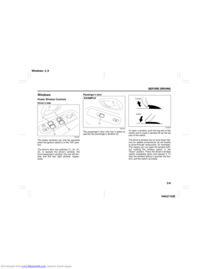 21
21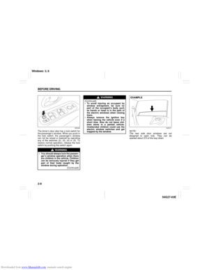 22
22 23
23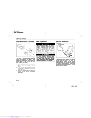 24
24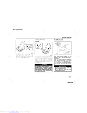 25
25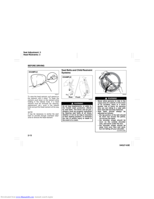 26
26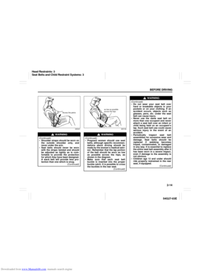 27
27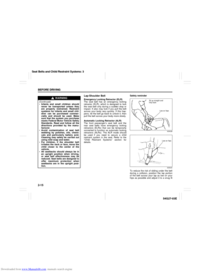 28
28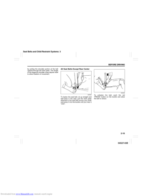 29
29 30
30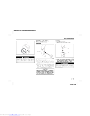 31
31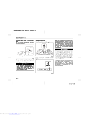 32
32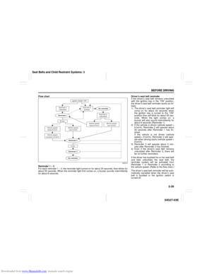 33
33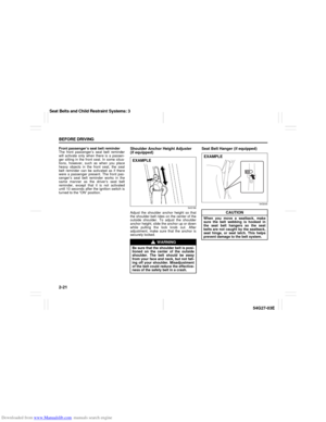 34
34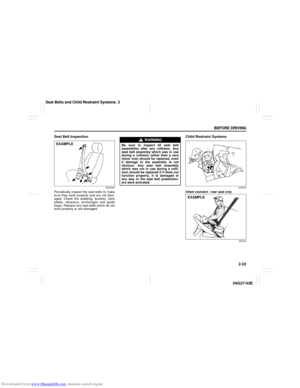 35
35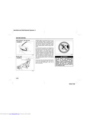 36
36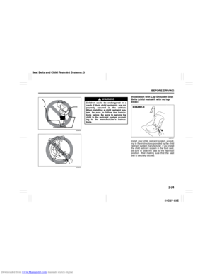 37
37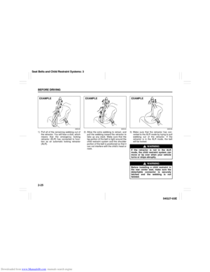 38
38 39
39 40
40 41
41 42
42 43
43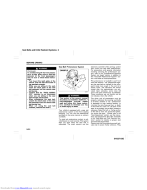 44
44 45
45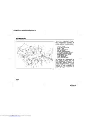 46
46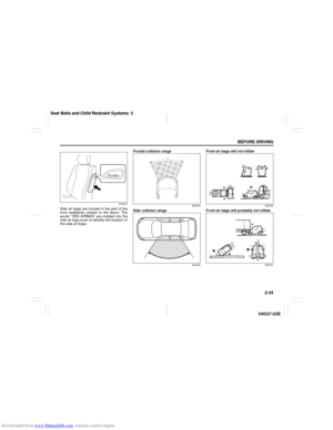 47
47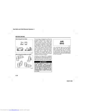 48
48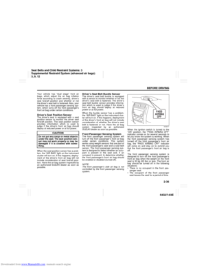 49
49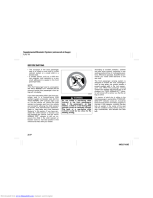 50
50 51
51 52
52 53
53 54
54 55
55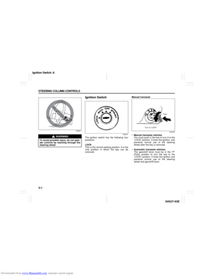 56
56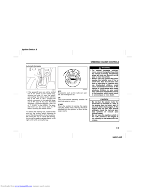 57
57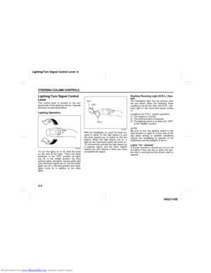 58
58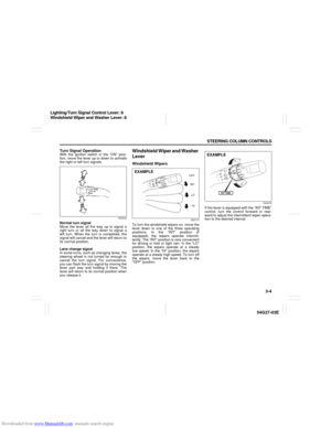 59
59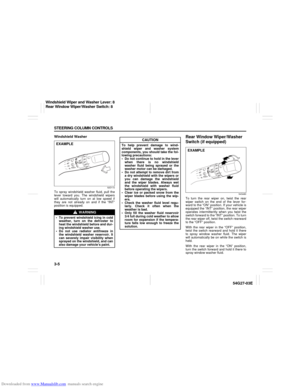 60
60 61
61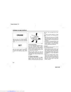 62
62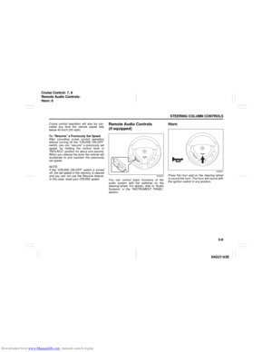 63
63 64
64 65
65 66
66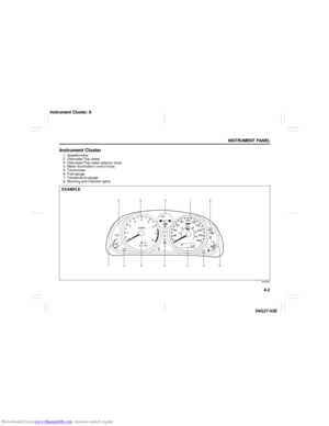 67
67 68
68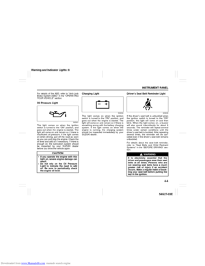 69
69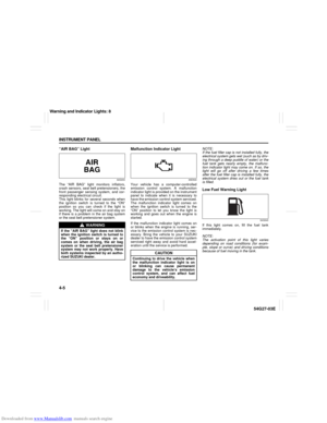 70
70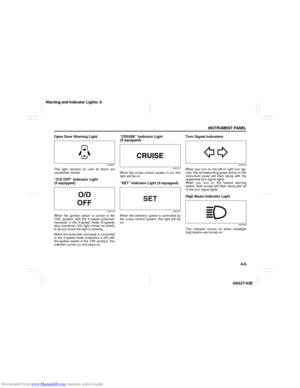 71
71 72
72 73
73 74
74 75
75 76
76 77
77 78
78 79
79 80
80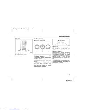 81
81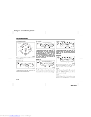 82
82 83
83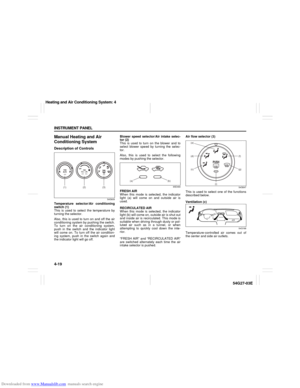 84
84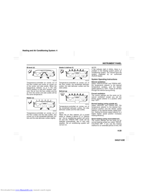 85
85 86
86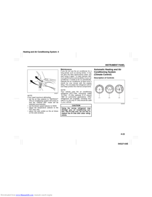 87
87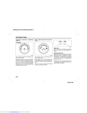 88
88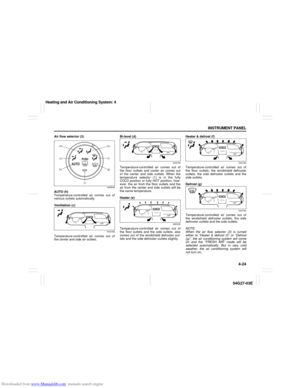 89
89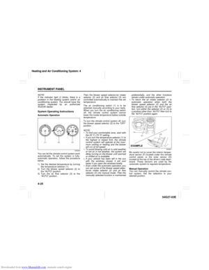 90
90 91
91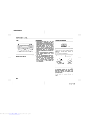 92
92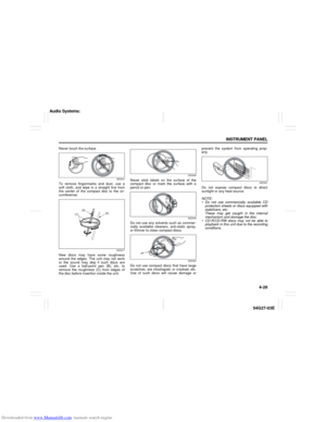 93
93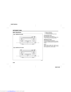 94
94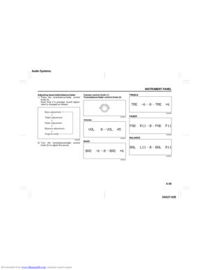 95
95 96
96 97
97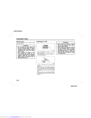 98
98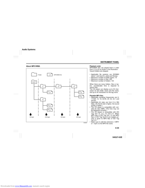 99
99 100
100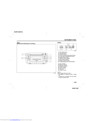 101
101 102
102 103
103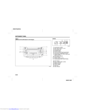 104
104 105
105 106
106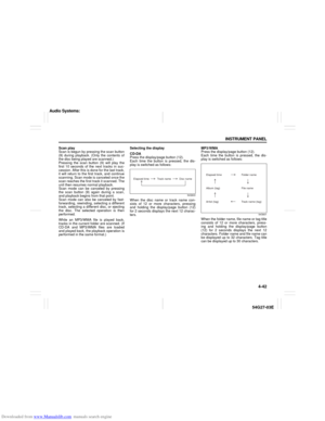 107
107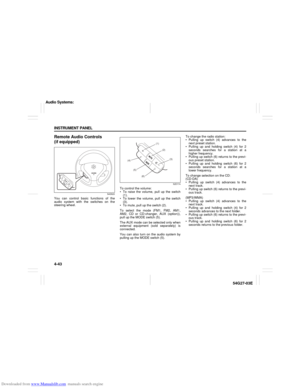 108
108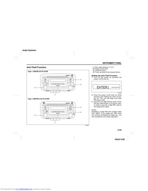 109
109 110
110 111
111 112
112 113
113 114
114 115
115 116
116 117
117 118
118 119
119 120
120 121
121 122
122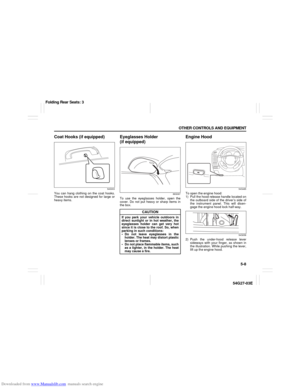 123
123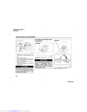 124
124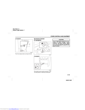 125
125 126
126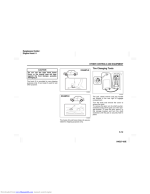 127
127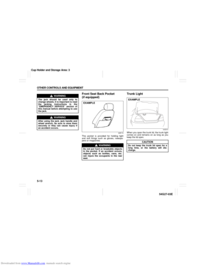 128
128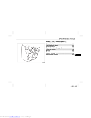 129
129 130
130 131
131 132
132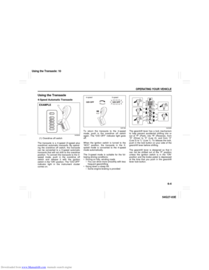 133
133 134
134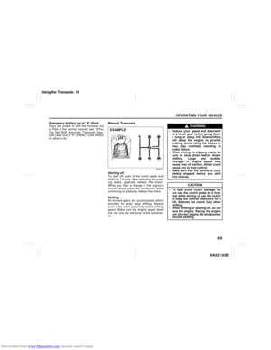 135
135 136
136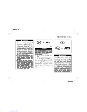 137
137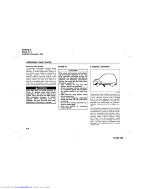 138
138 139
139 140
140 141
141 142
142 143
143 144
144 145
145 146
146 147
147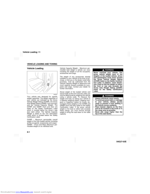 148
148 149
149 150
150 151
151 152
152 153
153 154
154 155
155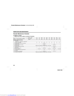 156
156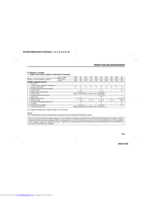 157
157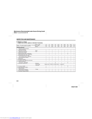 158
158 159
159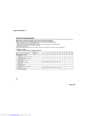 160
160 161
161 162
162 163
163 164
164 165
165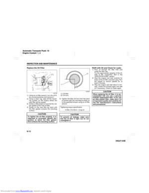 166
166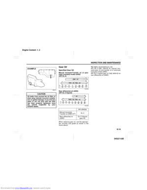 167
167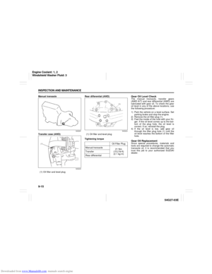 168
168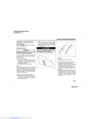 169
169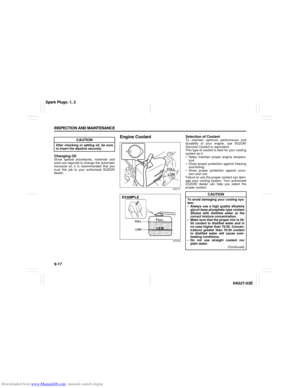 170
170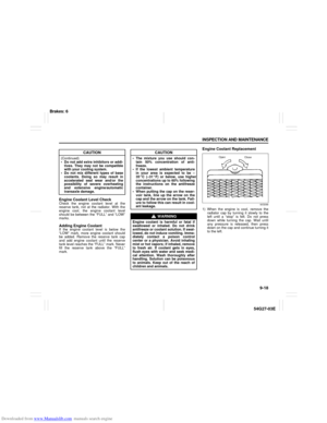 171
171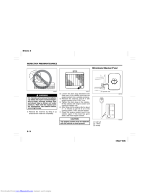 172
172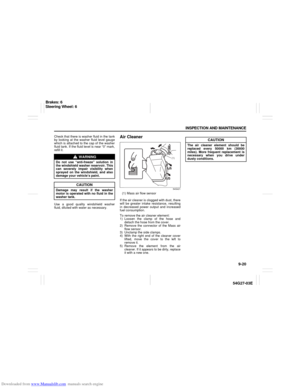 173
173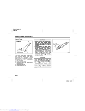 174
174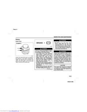 175
175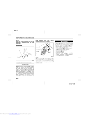 176
176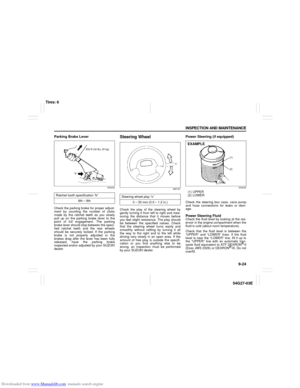 177
177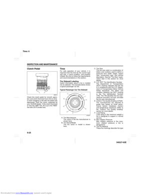 178
178 179
179 180
180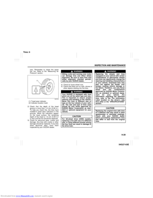 181
181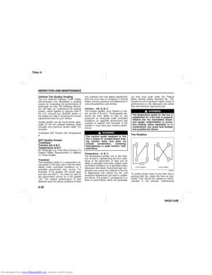 182
182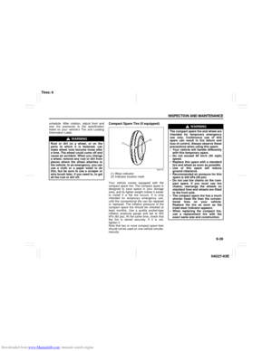 183
183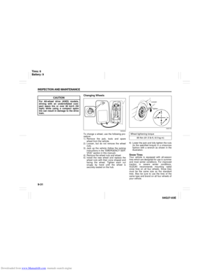 184
184 185
185 186
186 187
187 188
188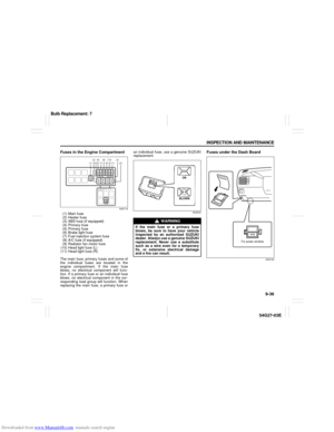 189
189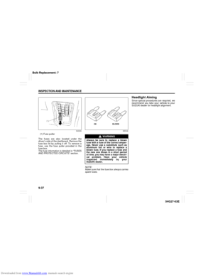 190
190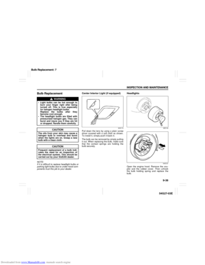 191
191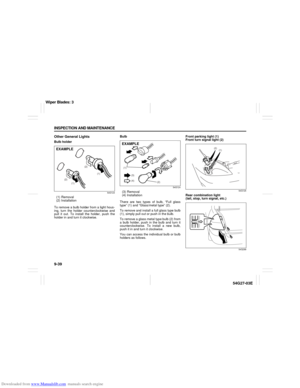 192
192 193
193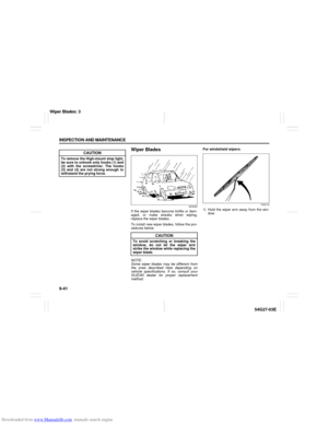 194
194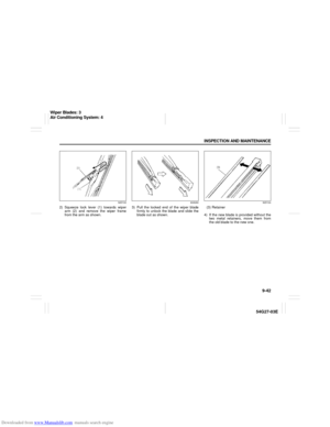 195
195 196
196 197
197 198
198 199
199 200
200 201
201 202
202 203
203 204
204 205
205 206
206 207
207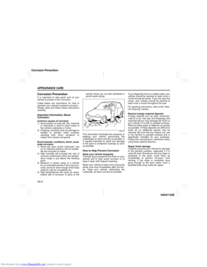 208
208 209
209 210
210 211
211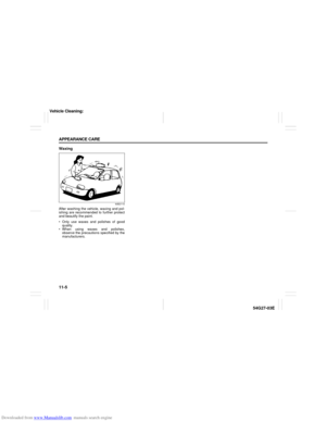 212
212 213
213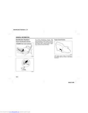 214
214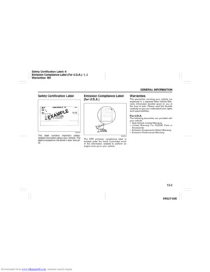 215
215 216
216 217
217 218
218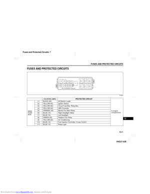 219
219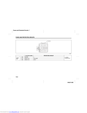 220
220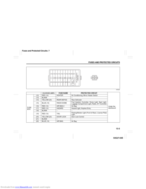 221
221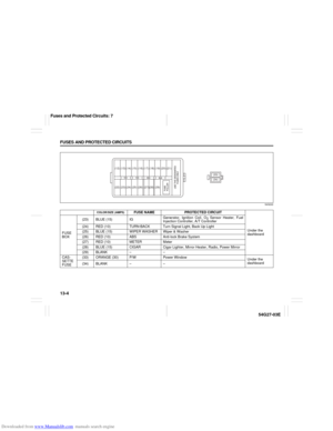 222
222 223
223 224
224 225
225 226
226 227
227 228
228 229
229 230
230 231
231 Fuse puller
The fuses are also located under the
driver’s side of the dashboard. Remove")
 Removal
(2) Installation
To remove a bulb holder from a li")