2007 SUZUKI AERIO air conditioning
[x] Cancel search: air conditioningPage 87 of 232

Downloaded from www.Manualslib.com manuals search engine 4-22 INSTRUMENT PANEL
54G27-03E
54G571
NOTE:
If you need maximum defrosting:
set the air flow selector to “DEFROST”
(the air conditioning system will come on
and the “FRESH AIR” mode will be
selected automatically),
set the blower speed selector to HIGH,
adjust the temperature selector to the
HOT end, and
adjust the side outlets so the air blows
on the side windows.
MaintenanceIf you do not use the air conditioner for a
long period, such as during winter, it may
not give the best performance when you
start using it again. To help maintain opti-
mum performance and durability of your air
conditioner, it needs to be run periodically.
Operate the air conditioner at least once a
month for one minute with the engine
idling. This circulates the refrigerant and oil
and helps protect the internal components.
NOTE:
Your vehicle uses the air conditioning
refrigerant HFC-134a, commonly called
“R-134a”. R-134a replaced R-12 around
1993 for automotive applications. Other
refrigerants are available, including recy-
cled R-12, but only R-134a should be used
in your vehicle.
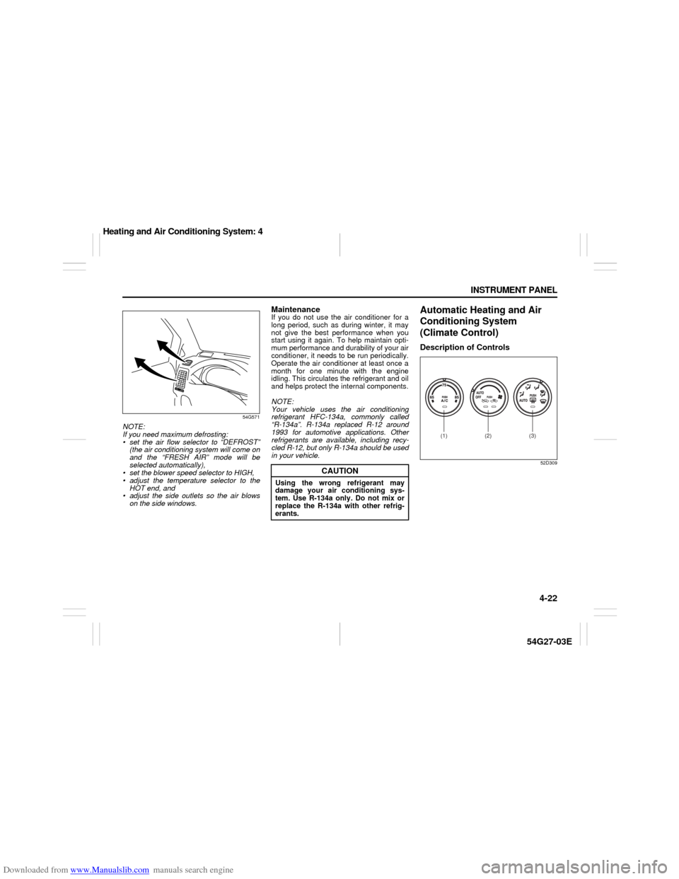
Automatic Heating and Air
Conditioning System
(Climate Control)Description of Controls
52D309
CAUTION
Using the wrong refrigerant may
damage your air conditioning sys-
tem. Use R-134a only. Do not mix or
replace the R-134a with other refrig-
erants.
(1) (2) (3)
Heating and Air Conditioning System: 4
Page 88 of 232

Downloaded from www.Manualslib.com manuals search engine 4-23 INSTRUMENT PANEL
54G27-03E
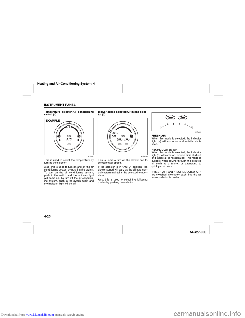
Temperature selector/Air conditioning
switch (1)
52D307
This is used to select the temperature by
turning the selector.
Also, this is used to turn on and off the air
conditioning system by pushing the switch.
To turn on the air conditioning system,
push in the switch and the indicator light
will come on. To turn off the air condition-
ing system, push in the switch again and
the indicator light will go off. Blower speed selector/Air intake selec-
tor (2)
65D498
This is used to turn on the blower and to
select blower speed.
If the selector is in “AUTO” position, the
blower speed will vary as the climate con-
trol system maintains the selected temper-
ature.
Also, this is used to select the following
modes by pushing the selector.
65D493
FRESH AIR
When this mode is selected, the indicator
light (a) will come on and outside air is
used.
RECIRCULATED AIR
When this mode is selected, the indicator
light (b) will come on, outside air is shut out
and inside air is recirculated. This mode is
suitable when driving through the polluted
air such as a tunnel, or attempting to
quickly cool down.
“FRESH AIR” and “RECIRCULATED AIR”
are switched alternately each time the air
intake selector is pushed.
EXAMPLE
(a) (b)
Heating and Air Conditioning System: 4
Page 89 of 232

Downloaded from www.Manualslib.com manuals search engine 4-24 INSTRUMENT PANEL
54G27-03E
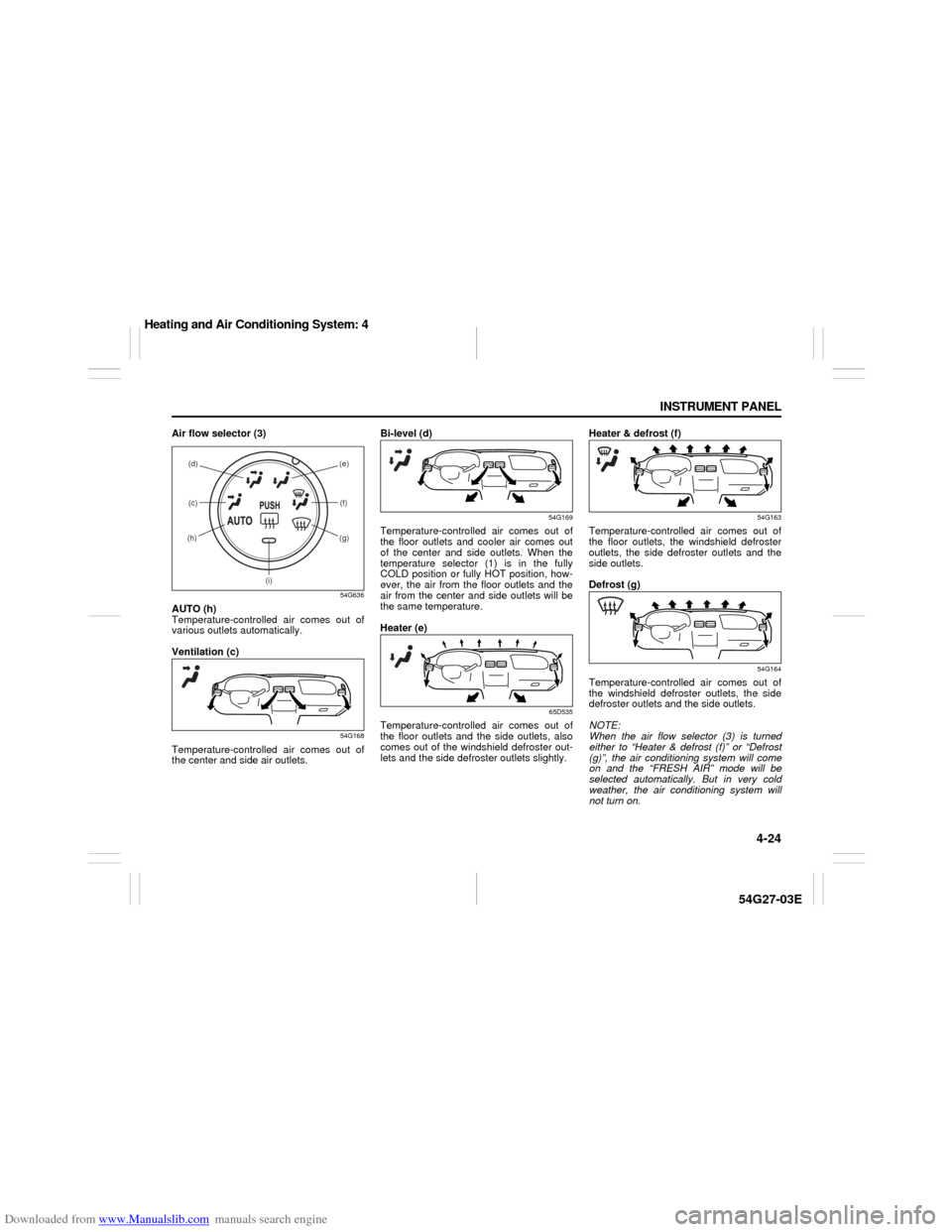
Air flow selector (3)
54G636
AUTO (h)
Temperature-controlled air comes out of
various outlets automatically.
Ventilation (c)
54G168
Temperature-controlled air comes out of
the center and side air outlets.Bi-level (d)
54G169
Temperature-controlled air comes out of
the floor outlets and cooler air comes out
of the center and side outlets. When the
temperature selector (1) is in the fully
COLD position or fully HOT position, how-
ever, the air from the floor outlets and the
air from the center and side outlets will be
the same temperature.
Heater (e)
65D535
Temperature-controlled air comes out of
the floor outlets and the side outlets, also
comes out of the windshield defroster out-
lets and the side defroster outlets slightly.Heater & defrost (f)
54G163
Temperature-controlled air comes out of
the floor outlets, the windshield defroster
outlets, the side defroster outlets and the
side outlets.
Defrost (g)
54G164
Temperature-controlled air comes out of
the windshield defroster outlets, the side
defroster outlets and the side outlets.
NOTE:
When the air flow selector (3) is turned
either to “Heater & defrost (f)” or “Defrost
(g)”, the air conditioning system will come
on and the “FRESH AIR” mode will be
selected automatically. But in very cold
weather, the air conditioning system will
not turn on.
(c) (d) (e)
(f)
(g)(h)
(i)
Heating and Air Conditioning System: 4
Page 90 of 232

Downloaded from www.Manualslib.com manuals search engine 4-25 INSTRUMENT PANEL
54G27-03E
NOTE:
If the indicator light (i) blinks, there is a
problem in the heating system and/or air
conditioning system. You should have the
system inspected by an authorized
SUZUKI dealer.System Operating InstructionsAutomatic Operation
52D308
You can let the climate control system work
automatically. To set the system in fully-
automatic operation, follow the procedure
below.
1) Set the desired temperature by turning
the temperature selector (1).
2) Turn the blower speed selector (2) to
the “AUTO” position.
3) Turn the air flow selector (3) to the
“AUTO” position.Then the blower speed selector/air intake
selector (2) and air flow selector (3) are
controlled automatically to maintain the set
temperature.
The air conditioning switch (1) is to be
selected manually according to your taste.
When you turn the air conditioning switch
off, the climate control system cannot
lower the inside temperature below outside
temperature.
To turn the climate control system off, turn
the blower speed selector (2) to the “OFF”
position
NOTE:
To find your comfortable zone, start with
the 25°C (75°F) setting.
If you turn the temperature selector (1) to
the highest or lowest limit, the climate
control system will operate at the maxi-
mum cooling or heating and the blower
will run at full speed.
To avoid blowing cold air in cold weather
or hot air in hot weather, the system will
delay turning on the blower until warmed
or chilled air is available.
If your vehicle has been left in the sun
with the windows closed, it will cool
faster if you open the windows briefly.
Even under the automatic operation, you
can set some of the blower speed selec-
tor/air intake selector (2) and air flow
selector (3) into manual mode. Then the
manually selected function is maintainedpreferentially, and the other functions
remain under automatic operation.
To return the air intake selector (2) to
automatic operation when both the
blower speed selector (2) and the air
flow selector (3) are in the “AUTO” posi-
tion, turn either the selector (2) or (3) to
a position other than “AUTO” then turn to
the “AUTO” position again.
54G507
Be careful not to cover the interior temper-
ature sensor (F) located under the climate
control panel, or the solar sensor (G)
located at the top of the driver’s side dash-
board. These sensors are used by the
automatic system to regulate temperature.
Manual Operation
You can manually control the climate con-
trol system. Set the selectors to your
desired position.
(1) (2) (3)
(F)
(G)
EXAMPLE
Heating and Air Conditioning System: 4
Page 91 of 232

Downloaded from www.Manualslib.com manuals search engine 4-26 INSTRUMENT PANEL
54G27-03E
54G571
NOTE:
If you need maximum defrosting:
set the air flow selector to “DEFROST”
(the air conditioning system will come on
and the “FRESH AIR” mode will be
selected automatically),
set the blower speed selector to HIGH,
adjust the temperature selector to the
HOT end, and
adjust the side outlets so the air blows
on the side windows.
MaintenanceIf you do not use the air conditioner for a
long period, such as during winter, it may
not give the best performance when you
start using it again. To help maintain opti-
mum performance and durability of your air
conditioner, it needs to be run periodically.
Operate the air conditioner at least once a
month for one minute with the engine
idling. This circulates the refrigerant and oil
and helps protect the internal components.
NOTE:
Your vehicle uses the air conditioning
refrigerant HFC-134a, commonly called
“R-134a”. R-134a replaced R-12 around
1993 for automotive applications. Other
refrigerants are available, including recy-
cled R-12, but only R-134a should be used
in your vehicle.
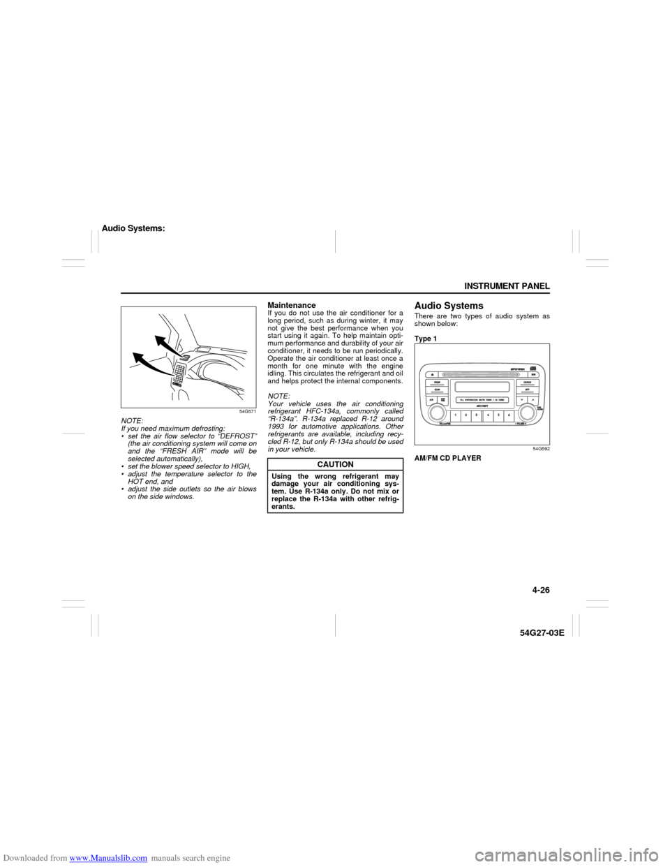
Audio SystemsThere are two types of audio system as
shown below:
Type 1
54G592
AM/FM CD PLAYER
CAUTION
Using the wrong refrigerant may
damage your air conditioning sys-
tem. Use R-134a only. Do not mix or
replace the R-134a with other refrig-
erants.
Audio Systems:
Page 130 of 232

Downloaded from www.Manualslib.com manuals search engine 6-1 OPERATING YOUR VEHICLE
54G27-03E
Exhaust Gas Warning
52D334
Daily Inspection ChecklistBefore Driving1) Make sure that windows, mirrors, lights
and reflectors are clean and unob-
structed.
2) Visually check the tires for the following
points:
– the depth of the tread groove
– abnormal wear, cracks and damage
– loose wheel nuts
– existence of foreign material such as
nails, stones, etc.
Refer to “Tires” in “INSPECTION AND
MAINTENANCE” section for details.
3) Look for fluid, oil leaks.
NOTE:
It is normal for water to drip from the air
conditioning system after use.
4) Make sure the hood is fully closed and
latched.
5) Check the headlights, turn signal lights,
brake lights and horn for proper opera-
tion.
6) Lock all doors.
7) Adjust the seat and adjustable head
restraints (if equipped).
8) Check the brake pedal.
9) Adjust the mirrors.
10)Make sure that you and all passengers
have properly fastened your seat belts.
11)Make sure that all warning lights come
on as the key is turned to the “ON” or
“START” position.
WARNING
Avoid breathing exhaust gases.
Exhaust gases contain carbon mon-
oxide, a potentially lethal gas that is
colorless and odorless. Since carbon
monoxide is difficult to detect by
itself, be sure to take the following
precautions to help prevent carbon
monoxide from entering your vehicle.
Do not leave the engine running in
garages or other confined areas.
(Continued)
WARNING
(Continued)
Do not park with the engine run-
ning for a long period of time, even
in an open area. If it is necessary to
sit for a short time in a parked vehi-
cle with the engine running, make
sure the air intake selector is set to
“FRESH AIR” and the blower is at
high speed.
Avoid operating the vehicle with
the trunk open. If it is necessary to
operate the vehicle with the trunk
open, make sure the sunroof (if
equipped) and all windows are
closed, and the blower is at high
speed with the air intake selector
set to “FRESH AIR”.
To allow proper operation of your
vehicle’s ventilation system, keep
the air inlet grille in front of the
windshield clear of snow, leaves or
other obstructions at all times.
Keep the exhaust tailpipe area clear
of snow and other material to help
reduce the buildup of exhaust
gases under the vehicle. This is
particularly important when parked
in blizzard conditions.
Have the exhaust system inspected
periodically for damage and leaks.
Any damage or leaks should be
repaired immediately.
Exhaust Gas Warning: NO
Daily Inspection Checklist: NO
Page 153 of 232

Downloaded from www.Manualslib.com manuals search engine INSPECTION AND MAINTENANCE
9
54G27-03E
60G410
INSPECTION AND MAINTENANCEMaintenance Schedule ....................................................... 9-2
Periodic Maintenance Schedule ........................................ 9-3
Maintenance Recommended under Severe Driving
Conditions ........................................................................... 9-7
Engine Oil and Filter ........................................................... 9-11
Gear Oil ................................................................................ 9-14
Automatic Transaxle Fluid ................................................. 9-16
Engine Coolant .................................................................... 9-17
Windshield Washer Fluid ................................................... 9-19
Air Cleaner ........................................................................... 9-20
Spark Plugs ......................................................................... 9-21
Brakes .................................................................................. 9-22
Steering Wheel .................................................................... 9-24
Clutch Pedal ........................................................................ 9-25
Tires ...................................................................................... 9-25
Battery .................................................................................. 9-35
Fuses .................................................................................... 9-35
Headlight Aiming ................................................................. 9-37
Bulb Replacement ............................................................... 9-38
Wiper Blades ....................................................................... 9-41
Air Conditioning System .................................................... 9-43
Page 185 of 232

Downloaded from www.Manualslib.com manuals search engine 9-32 INSPECTION AND MAINTENANCE
54G27-03E
GLOSSARY OF TIRE TERMINOL-
OGYAccessory Weight – the combined weight
(in excess of those standard items which
may be replaced) of automatic transaxle,
power steering, power brakes, power win-
dows, power seats, radio, and heater, to
the extent that these items are available as
factory-installed equipment (whether
installed or not).
Cold Tire Inflation Pressure – the pressure
in a tire that has been driven less than 1
mile or has been standing for three hours
or more.
Curb Weight – the weight of a motor vehi-
cle with standard equipment including the
maximum capacity of fuel, oil, and coolant,
and, if so equipped, air conditioning and
additional weight optional engine.
Intended Outboard Sidewall – (1) the side-
wall that contains a whitewall, bears white
lettering or bears manufacturer, brand,
and/or model name molding that is higher
or deeper than the same molding on the
other sidewall of the tire, or (2) the outward
facing sidewall of an asymmetrical tire that
has a particular side that must always face
outward when mounted on a vehicle.
Maximum Inflation Pressure – the maxi-
mum cold inflation pressure a tire is
designed to support in normal service.
Maximum Loaded Vehicle Weight – the
sum of curb weight, accessory weight,vehicle capacity weight (total load capac-
ity), and production options weight.
Normal Occupant Weight – 68 kilograms
times the number of occupants specified in
the second column of Table 1 (shown
below).
Occupant distribution – distribution of
occupants in a vehicle as specified in the
third column of Table 1 (shown below).
Production Options Weight – the combined
weight of those installed regular production
options weighing over 2.3 kilograms in
excess of those standard items which they
replace, not previously considered in curb
weight or accessory weight, including
heavy duty brakes, ride levelers, roof rack,
heavy duty battery, and special trim.
Recommended Inflation Pressure – the
cold tire inflation pressure recommended
by a manufacturer.
Rim – metal support for a tire or tire and
tube assembly upon which the tire beads
are seated.
Vehicle Capacity Weight – the rated cargo
and luggage load plus 68 kilograms (150
lbs) times the vehicle’s designated seating
capacity.
Vehicle Maximum Load on the Tire – the
load on an individual tire that is determined
by distributing to each axle its share of the
maximum loaded vehicle weight and divid-
ing by two.Vehicle Normal Load on the Tire – the load
on an individual tire that is determined by
distributing to each axle its share of the
curb weight, accessory weight, and normal
occupant weight (distributed in accordance
with Table 1 shown below) and dividing by
2.
TABLE 1 – Occupant Loading and Dis-
tribution For Vehicle Normal Load For
Various Designated Seating Capacities
Vehicle LoadingYour vehicle was designed for specific
load capacities. The load capacities of
your vehicle are indicated by the Gross
Vehicle Weight Rating (GVWR), the Gross
Axle Weight Rating (GAWR, front and
rear), and the total load capacity, the seat-
ing capacity, and the cargo load capacity.
The GVWR and GAWR (front and rear) are
listed on the Safety Certification Label
which is located below the driver’s side
door latch striker. The total load capacity
and seating capacity are listed on the Tire
and Loading Information Label which is
located below the Safety CertificationDesignated
seating capac-
ity, number of
occupantsVehicle normal
load, number
of occupantsOccupant
distribution in
a normally
loaded vehicle
2 through 4 2 2 in front
5 through 10 32 in front, 1 in
second seat
Fuses: 7