2007 SUBARU OUTBACK low oil pressure
[x] Cancel search: low oil pressurePage 24 of 442

&Warning and indicator light
Mark Name Page
Seatbelt warning light 3-22
Front passenger ’s seat-
belt warning light 3-22
SRS airbag system warn-
ing light3-24
CHECK ENGINE warning
light/Malfunction indicator lamp3-25
Charge warning light 3-26
Oil pressure warning light 3-26
AT OIL temperature
warning light (if equipped)
3-26
orABS warning light 3-28
orBrake system warning light
3-28
orDoor open warning light 3-29 Mark Name Page
Low fuel warning light 3-29
All-Wheel Drive warning
light (if equipped)
3-30
Vehicle Dynamics Control
operation indicator light (if
equipped)3-30
Vehicle Dynamics Control
warning light/Vehicle Dy-
namics Control OFF indi-
cator light (if equipped)3-30
Security indicator light 3-31
Turn signal indicator lights 3-33
High beam indicator light 3-33
Cruise control indicator
light (if equipped)
3-33
Cruise control set indica-
tor light (if equipped)
3-33
Light indicator light 3-33
Low tire pressure warning
light (if equipped)3-26Mark Name Page
orPassenger airbag ON in-
dicator light
3-25
orPassenger airbag OFF
indicator light
3-25
SPORT mode indicator
light (if equipped)3-32
orDaytime running lights in-
dicator light3-40
Shift up indicator (MT ve-
hicles) (if equipped)
3-32
S# PREP indicator
(if equipped) 3-721
– CONTINUED –
Page 122 of 442

Ignition switch..................................................... 3-3
LOCK .................................................................. 3-3
ACC.................................................................... 3-4
ON...................................................................... 3-4
START ................................................................ 3-4
Key reminder chime ............................................ 3-5
Ignition switch light ............................................. 3-5
Hazard warning flasher ....................................... 3-5
Meters and gauges (Turbo models) ................... 3-5
Combination meter illumination ........................... 3-5
Speedometer ....................................................... 3-6
Tachometer ......................................................... 3-6
Fuel gauge .......................................................... 3-6
Temperature gauge ............................................. 3-7
ECO gauge ......................................................... 3-8
Multi-information display (Turbo models) .......... 3-8
Odometer and trip meter ..................................... 3-9
Current and average fuel consumption ............... 3-10
Outside temperature and journey time ................ 3-11
Driving range on remaining fuel .......................... 3-13
Clock (Vehicle with Navigation System) ............... 3-14
SI-DRIVE display ................................................ 3-14
Warning messages and driver ’s
information ...................................................... 3-15
Meters and gauges (Non-turbo models) ........... 3-18
Combination meter illumination .......................... 3-18
Canceling the function for meter/gauge needle movement upon turning on the ignition switch .............................................................. 3-18
Speedometer ...................................................... 3-18
Odometer ........................................................... 3-19 Double trip meter
............................................... 3-19
Tachometer ....................................................... 3-20
Fuel gauge ........................................................ 3-20
Temperature gauge ............................................ 3-21
Warning and indicator lights ............................. 3-22
Seatbelt warning light and chime ....................... 3-22
SRS airbag system warning light ........................ 3-24
Front passenger ’s frontal airbag ON and OFF
indicators ........................................................ 3-25
CHECK ENGINE warning light/Malfunction indicator lamp ................................................. 3-25
Charge warning light .......................................... 3-26
Oil pressure warning light .................................. 3-26
AT OIL TEMPerature warning light (AT vehicles) .................................................... 3-26
Low tire pressure warning light (if equipped) .................................................... 3-26
ABS warning light .............................................. 3-28
Brake system warning light ................................ 3-28
Low fuel warning light ....................................... 3-29
Door open warning light .................................... 3-29
All-Wheel Drive warning light (AT vehicles) .................................................... 3-30
Vehicle Dynamics Control operation indicator light (if equipped). ............................................ 3-30
Vehicle Dynamics Control warning light (if equipped)/Vehicle Dynamics Control OFF
indicator light (if equipped) .............................. 3-30
Security indicator light ....................................... 3-31
SPORT mode indicator light (if equipped) ........... 3-32
Shift-up indicator light (MT vehicles) (if equipped) .................................................... 3-32
Instruments and controls
3
Page 143 of 442

3-22Instruments and controls
Warning and indicator lights
Several of the warning and indicator lights
come on momentarily and then go out
when the ignition switch is initially turned
to the“ON ”position. This permits check-
ing the operation of the bulbs.
Apply the parking brake and turn the
ignition switch to the “ON ”position. The
following lights come on:
: Seatbelt warning light
(The seatbelt warning light goes out only
when the driver fastens the seatbelt.)
: Front passenger ’s seatbelt warning
light
(The seatbelt warning light goes out only
when the front seat passenger fastens theseatbelt.)
: SRS airbag system warning light
: CHECK ENGINE warning light/Mal- function indicator lamp
: Charge warning light
: Oil pressure warning light
: AT OIL temperature warning light (ATvehicles)
/: ABS warning light
: Vehicle Dynamics Control operation indicator light (if equipped)
: Vehicle Dynamics Control warning light
(if equipped)/Vehicle Dynamics Control
OFF indicator light (if equipped)
/: Brake system warning light
: AWD warning light (AT vehicles)
: Low tire pressure warning light (if equipped)
: SPORT mode indicator light (AT vehicles)
/: Front passenger ’s frontal airbag
ON indicator light
/: Front passenger ’s frontal airbag
OFF indicator light
: Low fuel warning light
/: Door open warning light
: Cruise control indicator light (if equipped)
: Cruise control set indicator light (if
equipped)
: Shift-up indicator light (MT vehicles) (ifequipped)
: S# PREP indicator light (if equipped)
If any lights fail to come on, it indicates a burned-out bulb or a malfunction of the
corresponding system.
Consult your authorized SUBARU dealer
for repair.
& Seatbelt warning light
and chime
Your vehicle is equipped with a seatbelt
warning device at the driver ’s and front
passenger ’s seat, as required by current
safety standards.
With the ignition switch turned to the “ON ”
position, this device reminds the driver
and front passenger to fasten their seat-
belts by illuminating the warning lights in
the locations indicated in the following
illustration and sounding a chime.
Driver ’s warning light (Turbo models)
Page 147 of 442

3-26Instruments and controls
turn off immediately. It may take several
driving trips. If the light does not go out,
take your vehicle to your authorized
SUBARU dealer immediately. !If the light is blinking:
If the light is blinking while driving, an
engine misfire condition has been de-
tected which may damage the emission
control system.
To prevent serious damage to the emis-
sion control system, you should do thefollowing. . Reduce vehicle speed.
. Avoid hard acceleration.
. Avoid steep uphill grades.
. Reduce the amount of cargo, if possi-
ble.. Stop towing a trailer as soon as
possible.
The CHECK ENGINE warning light/mal-
function indicator lamp may stop blinking
and come on steadily after several driving
trips. You should have your vehicle
checked by an authorized SUBARU deal-
er immediately. & Charge warning light
If this light comes on when the engine is
running, it may indicate that the charging system is not working properly.
If the light comes on while driving or does
not go out after the engine starts, stop the
engine at the first safe opportunity and
check the alternator belt. If the belt is
loose, broken or if the belt is in good
condition but the light remains on, contact
your nearest SUBARU dealer immedi-
ately.
& Oil pressure warning light
CAUTION
Do not operate the engine with the
oil pressure warning light on. This
may cause serious engine damage.
If this light comes on when the engine is
running, it may indicate that the engine oil
pressure is low and the lubricating system
is not working properly.
If the light comes on while driving or does
not go out after the engine starts, stop the
engine at the first safe opportunity and
check the engine oil level. If the oil level is
low, add oil immediately. If the engine oil is
at the proper level but the light remains on,
contact your nearest SUBARU dealer
immediately. &
AT OIL TEMPerature
warning light (AT vehi- cles)
The AT oil temperature warning light
comes on when the ignition switch is
turned to the “ON ”position and goes out
after approximately two seconds.
If this light comes on when the engine is
running, it may indicate that the automatic
transmission fluid temperature is too hot.
If the light comes on while driving, it is
unnecessary to stop the vehicle, but avoid
driving up steep grades or in stop-and-gotraffic. ! Automatic transmission control
system warning
If the light flashes after the engine starts, it
may indicate that the automatic transmis-
sion control system is not working prop-
erly. Contact your nearest SUBARU
dealer for service immediately. & Low tire pressure
warning light (ifequipped)
When the ignition switch is turned to the “ON ”position, the low tire pressure warn-
ing light will come on for approximately 2
seconds to check that the tire pressure
monitoring system (TPMS) is functioning
Page 329 of 442

9-12In case of emergency
5. Start the engine of the vehicle with the
booster battery and run it at moderate
speed. Then start the engine of the vehicle
that has the discharged battery.
6. When finished, carefully disconnect
the cables in exactly the reverse order. Engine overheating
WARNING
Never attempt to remove the radia-
tor cap until the engine has been
shut off and has fully cooled down.
When the engine is hot, the coolant
is under pressure. Removing the
cap while the engine is still hot
could release a spray of boiling hot
coolant, which could burn you very
seriously.
If the engine overheats, pull off the road
safely and stop the vehicle in a safe place. & If steam is coming from the
engine compartment
Turn off the engine and get everyone
away from the vehicle until it cools down. & If no steam is coming from
the engine compartment
1. Keep the engine running at idling speed.
2. Open the hood to ventilate the engine compartment.
Confirm that the cooling fan is turning. If
the fan is not turning, immediately turn off the engine and contact your authorized
dealer for repair.
3. After the engine coolant temperature
has dropped, turn off the engine.
If the temperature gauge stays at the
overheated zone, turn off the engine.
4. After the engine has fully cooled down,
check the coolant level in the reservetank.
If the coolant level is below the
“MIN ”
mark, add coolant up to the “MAX ”mark.
5. If there is no coolant in the reserve
tank, add coolant to the reserve tank.
Then remove the radiator cap and fill the
radiator with coolant.
If you remove the radiator cap from a hot
radiator, first wrap a thick cloth around the
radiator cap, then turn the cap counter-
clockwise slowly without pressing down
until it stops. Release the pressure from
the radiator. After the pressure has been
fully released, remove the cap by pressing
down and turning it.
Page 356 of 442

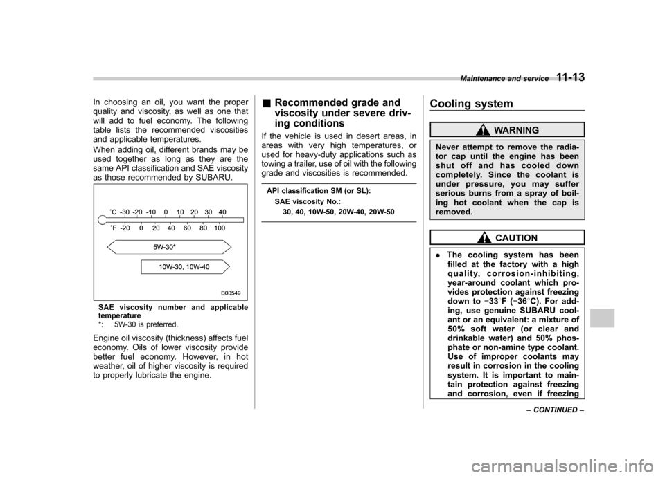
In choosing an oil, you want the proper
quality and viscosity, as well as one that
will add to fuel economy. The following
table lists the recommended viscosities
and applicable temperatures.
When adding oil, different brands may be
used together as long as they are the
same API classification and SAE viscosity
as those recommended by SUBARU.
SAE viscosity number and applicable
temperature
*: 5W-30 is preferred.
Engine oil viscosity (thickness) affects fuel
economy. Oils of lower viscosity provide
better fuel economy. However, in hot
weather, oil of higher viscosity is required
to properly lubricate the engine. &
Recommended grade and
viscosity under severe driv-
ing conditions
If the vehicle is used in desert areas, in
areas with very high temperatures, or
used for heavy-duty applications such as
towing a trailer, use of oil with the following
grade and viscosities is recommended.
API classification SM (or SL): SAE viscosity No.: 30, 40, 10W-50, 20W-40, 20W-50 Cooling system
WARNING
Never attempt to remove the radia-
tor cap until the engine has been
shut off and has cooled down
completely. Since the coolant is
under pressure, you may suffer
serious burns from a spray of boil-
ing hot coolant when the cap isremoved.
CAUTION
. The cooling system has been
filled at the factory with a high
quality, corrosion-inhibiting,
year-around coolant which pro-
vides protection against freezing
down to �33 8F( �36 8C). For add-
ing, use genuine SUBARU cool-
ant or an equivalent: a mixture of
50% soft water (or clear and
drinkable water) and 50% phos-
phate or non-amine type coolant.
Use of improper coolants may
result in corrosion in the cooling
system. It is important to main-
tain protection against freezing
and corrosion, even if freezing Maintenance and service
11-13
– CONTINUED –
Page 358 of 442

.Do not splash the engine coolant
over painted parts. The alcohol
contained in the engine coolant
may damage the paint surface.
! Changing the coolant
Always add genuine Subaru cooling sys-
tem conditioner whenever the coolant isreplaced.
Change the engine coolant and add
genuine Subaru cooling system condi-
tioner using the following procedures
according to the maintenance schedule
in the “Warranty and Maintenance Book-
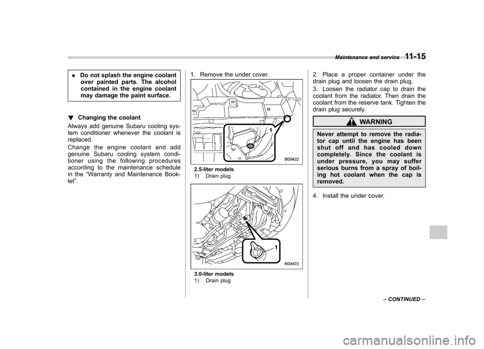
let ”. 1. Remove the under cover.
2.5-liter models
1) Drain plug
3.0-liter models
1) Drain plug 2. Place a proper container under the
drain plug and loosen the drain plug.
3. Loosen the radiator cap to drain the
coolant from the radiator. Then drain the
coolant from the reserve tank. Tighten the
drain plug securely.
WARNING
Never attempt to remove the radia-
tor cap until the engine has been
shut off and has cooled down
completely. Since the coolant is
under pressure, you may suffer
serious burns from a spray of boil-
ing hot coolant when the cap is removed.
4. Install the under cover. Maintenance and service
11-15
– CONTINUED –
Page 422 of 442

an asymmetrical tire that has a
particular side that must always
face outward when mounting on a
vehicle.
. Accessory weight
The combined weight (in excess of
those standard items which may be
replaced) of floor mats, leather seats
and cross bars to the extent that these
items are available as factory-in-
stalled equipment (whether installed
or not). . Curb weight
The weight of a motor vehicle with
standard equipment including the
maximum capacity of fuel, oil, and
coolant and air conditioning. . Maximum loaded vehicle weight
The sum of curb weight, accessory
weight, vehicle capacity weight and
production options weight. . Normal occupant weight
150 lbs (68 kg) times the number of
occupants (3 occupants). . Occupant distribution
Distribution of occupants in a vehicle,
2 in front, 1 in rear seat. . Production options weight The combined weight of those in-
stalled regular production options
weighing over 5.1 lbs (2.3 kg) in
excess of those standards items
which they replace, not previously
considered in curb weight or acces-
sory weight. .
Vehicle capacity weight
The total weight of cargo, luggage
and occupants that can be added to
the vehicle. . Vehicle maximum load on a tire
Load on an individual tire that is
determined by distributing to each
axle its share of the maximum loaded
vehicle weight and dividing by two. . Vehicle normal load on a tire
Load on an individual tire that is
determined by distributing to each
axle its share of the curb weight,
accessory weight, and normal occu-
pant weight and dividing by two. & Tire care –maintenance and
safety practices
. Check on a daily basis that the tires
are free from serious damage, nails,
and stones. At the same time, check
the tires for abnormal wear. .
Inspect the tire tread regularly and
replace the tires before their tread
wear indicators become visible. When
a tire ’s tread wear indicator becomes
visible, the tire is worn beyond the
acceptable limit and must be replaced
immediately. With a tire in this condi-
tion, driving at even low speeds in wet
weather can cause the vehicle to
hydroplane. Possible resulting loss
of vehicle control can lead to an
accident. . To maximize the life of each tire
and ensure that the tires wear uni-
formly, it is best to rotate the tires
every 7,500 miles (12,500 km). Rotat-
ing the tires involves switching the
front and rear tires on the right-hand
side of the vehicle and similarly
switching the front and rear tires on
the left-hand side of the vehicle.
(Each tire must be kept on its original
side of the vehicle.) Replace any
damaged or unevenly worn tire at
the time of rotation. After tire rotation,
adjust the tire pressures and make
sure the wheel nuts are correctly
tightened. A tightening torque specifi-
cation and a tightening sequence
Consumer information and Reporting safety defects
13-7
– CONTINUED –