2007 SUBARU IMPREZA set clock
[x] Cancel search: set clockPage 170 of 364
5-12Audio
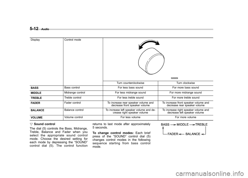
Display Control mode
Turn counterclockwise Turn clockwise
BASS Bass control For less bass sound For more bass sound
MIDDLE Midrange control For less midrange sound For more midrange sound
TREBLE Treble control For less treble sound For more treble sound
FADER Fader control To increase rear speaker volume and
decrease front speaker volume To increase front speaker volume and
decrease rear speaker volume
BALANCE Balance control To increase left speaker volume and de-
crease right speaker volume To increase right speaker volume and
decrease left speaker volume
VOLUME Volume control For less volume For more volume
! Sound control
The dial (5) controls the Bass, Midrange,
Treble, Balance and Fader when you
select the appropriate sound control
mode. Choose the desired setting for
each mode by depressing the “SOUND ”
controldial(5).Thecontrolfunction returns to last mode after approximately
5 seconds.
To change control modes:
Each brief
press of the “SOUND ”control dial (5)
changes control modes in the following
sequence starting from bass controlmode.
Page 171 of 364
!Display illumination dimness cance-
lation (BRIGHT)
The brightness of the radio display dims
when the light switch is in the “
”or
“” position. If this makes the display
difficult to read, press the volume dial for
more than 2 seconds to return the display
to original brightness. Subsequently
pressing the volume dial again for more
than 2 seconds or if you can safely do so,
turning the light switch to the OFF position
and back to the “
”or “”position
makes the radio display dim again. ! FM/AM selection button (FM/AM)
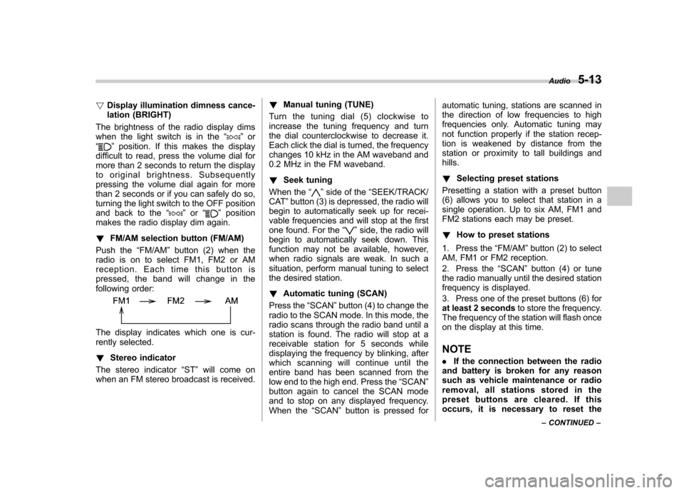
Push the “FM/AM ”button (2) when the
radio is on to select FM1, FM2 or AM
reception. Each time this button is
pressed, the band will change in the
following order:
The display indicates which one is cur-
rently selected. ! Stereo indicator
The stereo indicator “ST ”will come on
when an FM stereo broadcast is received. !
Manual tuning (TUNE)
Turn the tuning dial (5) clockwise to
increase the tuning frequency and turn
the dial counterclockwise to decrease it.
Each click the dial is turned, the frequency
changes 10 kHz in the AM waveband and
0.2 MHz in the FM waveband. ! Seek tuning
When the “
”side of the “SEEK/TRACK/
CAT ”button (3) is depressed, the radio will
begin to automatically seek up for recei-
vable frequencies and will stop at the first
one found. For the “
”side, the radio will
begin to automatically seek down. This
function may not be available, however,
when radio signals are weak. In such a
situation, perform manual tuning to select
the desired station. ! Automatic tuning (SCAN)
Press the “SCAN ”button (4) to change the
radio to the SCAN mode. In this mode, the
radio scans through the radio band until a
station is found. The radio will stop at a
receivable station for 5 seconds while
displaying the frequency by blinking, after
which scanning will continue until the
entire band has been scanned from the
low end to the high end. Press the “SCAN ”
button again to cancel the SCAN mode
and to stop on any displayed frequency.
When the “SCAN ”button is pressed for automatic tuning, stations are scanned in
the direction of low frequencies to high
frequencies only. Automatic tuning may
not function properly if the station recep-
tion is weakened by distance from the
station or proximity to tall buildings andhills. !
Selecting preset stations
Presetting a station with a preset button
(6) allows you to select that station in a
single operation. Up to six AM, FM1 and
FM2 stations each may be preset. ! How to preset stations
1. Press the “FM/AM ”button (2) to select
AM, FM1 or FM2 reception.
2. Press the “SCAN ”button (4) or tune
the radio manually until the desired station
frequency is displayed.
3. Press one of the preset buttons (6) for
at least 2 seconds to store the frequency.
The frequency of the station will flash once
on the display at this time. NOTE . If the connection between the radio
and battery is broken for any reason
such as vehicle maintenance or radio
removal, all stations stored in the
preset buttons are cleared. If this
occurs, it is necessary to reset the Audio
5-13
– CONTINUED –
Page 180 of 364
5-22Audio
! Displaying Sirius ID of tuner
When you activate Sirius, you should
have your Sirius tuner ID ready because
each tuner is identified by its unique Sirius
tuner ID.
The Sirius ID will be needed when you
activate Sirius and receive Sirius custo-
mer support.
The Sirius ID can be found on the audio
display by tuning the channel to “0 ”.
Turn the “TUNE/FOLDER/CH ”dial (23) to
select the satellite radio channel. ! Channel selection
Turn the “TUNE/FOLDER/CH ”dial (23) to
select the radio channel. Turn the tuning
dial clockwise to change the channel
upward and turn the dial counterclockwise
to change the channel downward with
each click of the dial. ! Category selection
Press the “SEEK/TRACK/CAT ”button
(18) to select the category of radio
channel. Press the “
”side of the button
(18) to change the category upward and the “
”side of the button to downward
with each press of the button. ! Channel preset
Presetting a channel with a preset button
(22) allows you to select that station in a
single operation. Up to six SR1, SR2 and SR3 channels each may be preset.
Press one of the preset buttons for
at
least 2 seconds to store the channel. The
number of the channel will flash once on
the display, and the unit produces a beep
sound at this time. ! Channel scan
Press the “SCAN ”button (19) to change
the radio to the SCAN mode. In this mode,
the radio scans through the channel until a
station is found. The radio will stop at the
station for 5 seconds while displaying the
channel number, after which scanning will
continue until the entire channel has been
scanned from the low end to the high end.
Press the “SCAN ”button (19) again to
cancel the SCAN mode and to stop on any
displayed station.
When the “SCAN ”button is pressed for
automatic tuning, stations are only
scanned in an upward direction. ! Category mode
Press the “CAT ”button (21) for at least 2
seconds to turn the category mode on. In
this mode, the radio operations (channel
selection, channel scan) are performed
only in the selected category. To cancel
the category mode, press the “CAT ”button
(21) for at least 2 seconds again. !
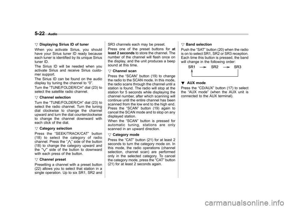
Band selection
Push the “SAT ”button (20) when the radio
is on to select SR1, SR2 or SR3 reception.
Each time this button is pressed, the band
will change in the following order:
! AUX mode
Press the “CD/AUX ”button (17) to select
the “AUX mode ”(when the AUX unit is
connected to the AUX terminal).
Page 324 of 364
11-48Maintenance and service
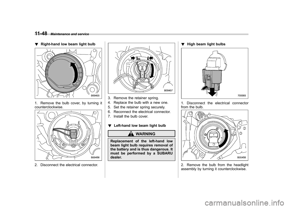
!Right-hand low beam light bulb
1. Remove the bulb cover, by turning it counterclockwise.
2. Disconnect the electrical connector.
3. Remove the retainer spring.
4. Replace the bulb with a new one.
5. Set the retainer spring securely.
6. Reconnect the electrical connector.
7. Install the bulb cover. !Left-hand low beam light bulb
WARNING
Replacement of the left-hand low
beam light bulb requires removal of
the battery and is thus dangerous. It
must be performed by a SUBARU
dealer. !
High beam light bulbs
1. Disconnect the electrical connector
from the bulb.
2. Remove the bulb from the headlight
assembly by turning it counterclockwise.
Page 325 of 364
3. Replace the bulb with a new one.
4. Reconnect the electrical connector. At
this time, use care not to touch the bulbsurface.
5. To install the bulb to the headlight
assembly, turn it clockwise until it clicks. &Front turn signal light bulbs
It may be difficult to replace the bulbs.
Have your SUBARU dealer replace the
bulbs if necessary. & Parking light
It may be difficult to replace the bulbs.
Have your SUBARU dealer replace the
bulbs if necessary. & Front fog light
It may be difficult to replace the bulbs.
Have your SUBARU dealer replace the
bulbs if necessary. &
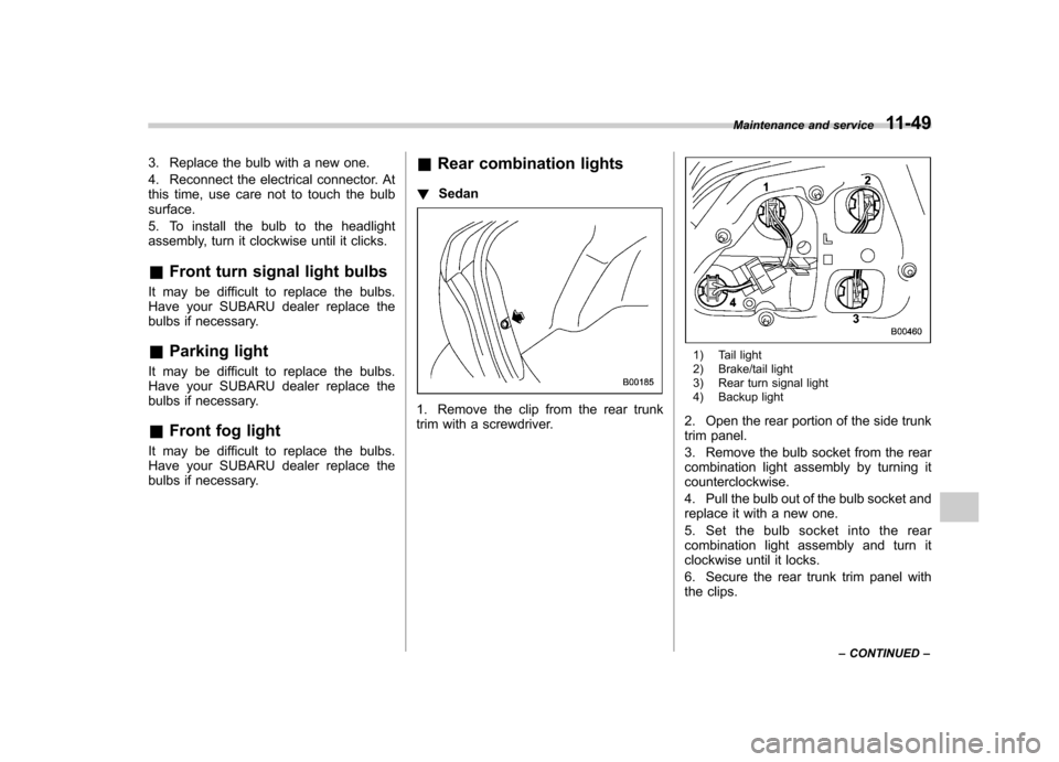
Rear combination lights
! Sedan
1. Remove the clip from the rear trunk
trim with a screwdriver.
1) Tail light
2) Brake/tail light
3) Rear turn signal light
4) Backup light
2. Open the rear portion of the side trunk
trim panel.
3. Remove the bulb socket from the rear
combination light assembly by turning itcounterclockwise.
4. Pull the bulb out of the bulb socket and
replace it with a new one.
5. Set the bulb socket into the rear
combination light assembly and turn it
clockwise until it locks.
6. Secure the rear trunk trim panel with
the clips. Maintenance and service
11-49
– CONTINUED –
Page 326 of 364
11-50Maintenance and service
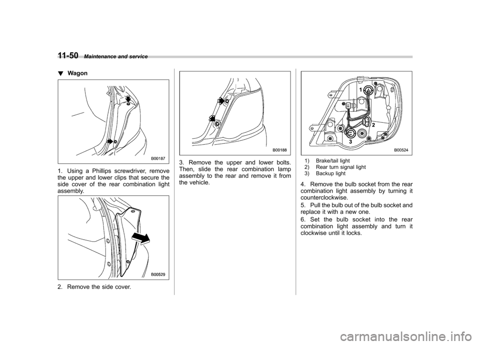
! Wagon
1. Using a Phillips screwdriver, remove
the upper and lower clips that secure the
side cover of the rear combination light
assembly.
2. Remove the side cover.
3. Remove the upper and lower bolts.
Then, slide the rear combination lamp
assembly to the rear and remove it from
the vehicle.1) Brake/tail light
2) Rear turn signal light
3) Backup light
4. Remove the bulb socket from the rear
combination light assembly by turning itcounterclockwise.
5. Pull the bulb out of the bulb socket and
replace it with a new one.
6. Set the bulb socket into the rear
combination light assembly and turn it
clockwise until it locks.
Page 356 of 364
CenterConsole .................................................................. 6-4
Ventilators ............................................................... 4-3
Center and side ventilators ............................................ 4-3
Changing Flat tire ................................................................... 9-4
Oil and oil filter ...................................................... 11-9
Charge warning light .................................................. 3-16
CHECK ENGINE warning light/Malfunction indicator lamp ...................................................................... 3-16
Checking Brake pedal free play ............................................ 11-27
Brake pedal reserve distance ................................. 11-28
Clutch function ...................................................... 11-28
Clutch pedal free play ............................................ 11-28
Engine oil level ...................................................... 11-8
Fluid level ............................... 11-20, 11-24, 11-25, 11-26
Gear oil level ........................................................ 11-22
Child restraint systems ............................................... 1-22
Installation with A/ELR seatbelt ................................ 1-25
Lower and tether anchorages .................................. 1-29
Child safety .................................................................... 5
Locks ................................................................... 2-18
Chime Key ........................................................................ 3-5 Seatbelt ........................................................ 1-11, 3-14
Cleaning
Aluminum wheels ................................................... 10-3
Interior .................................................................. 10-5
Ventilation grille ..................................................... 4-11 Climate control system
Automatic ............................................................... 4-8
Manual ................................................................... 4-3
Clock ........................................................................ 3-22
Clutch Fluid ................................................................... 11-26
Pedal .................................................................. 11-28
Coat hook. .................................................................. 6-9
Coin tray .................................................................... 6-4
Cooling system ........................................................ 11-12
Corrosion protection ............................................ 8-10, 10-4
Cruise control ............................................................ 7-26
Set indicator light .................................................... 3-20
Cruise control indicator light ......................................... 3-20
Cup holder ................................................................. 6-5
Front passenger ’s.................................................... 6-5
Rear passenger ’s .................................................... 6-6
D
Daytime running light system ....................................... 3-23
Differential gear oil
Front ................................................................... 11-21
Rear ................................................................... 11-22
Dimensions ................................................................ 12-2
Disarming the system ................................................. 2-15
Disc brake pad wear warning indicators ........................ 7-21
Dome light .................................................................. 6-2
Door
Locks ..................................................................... 2-4
Open warning light. ................................................. 3-19
Drive belts ............................................................... 11-18 Index
14-3