Page 258 of 465

0-9
PARKING AID SYSTEM
RODIUS 2006.09
8790-04
3) Cautions on parking aid system
Note that the display does not show everything in the rear area.
Always check nobody, especially animals and children, is behind the vehicle.
Normal precautions when reversing should be maintained. *
*
The parking aid system is just a supplemental device to help your parking operation.
Always keep the safety precautions.
Do not press or shock the sensors by hitting or high-pressure water gun while washing, o
r
the sensors will be damaged.
If the system is in normal operating conditions, a short beep sounds when the gear selecto
r
lever is moved into “R” position with the ignition key “ON”.
If the system is in abnormal operating conditions, a beep sounds for 3 seconds when the
gear selector lever is moved into “R” position with the ignition key “ON” or engine
running. However, it is also occurred when the obstacle is within 50 cm from the rea
r
bumper. 1.
2.
3.
4.
5.
(1) The parking aid system will not work or improperly work under
following cases:
▶Certain obstacles that sensors can not detect
- Wires, ropes, chains.
- Cotton, sponge, clothes, snow that absorb ultrasonic waves.
- Obstacles lower than the bumper.
▶Not defective but improperly working
- When the sensing portion is frozen.
- When the sensing portion is covered by rain, water drops, snow or mud.
- When receiving other ultrasonic signals
(metal sound or air braking noises from heavy commercial vehicles).
- When a high-power radio is turned on.
▶Narrowed sensing area
- When the sensing portion is partially covered by snow or mud.
<00540047007a009c009900990096009c0095008b00900095008e0047009b008c00940097008c00990088009b009c0099008c00470096008d0047009a008c0095009a0096009900470090009a0047009b009600960047008f0090008e008f0047004f008800
97009700990096009f005500470096009d008c00990047005f>0°C) or too low (approx.
below -
30°C)
▶Not defective but may occur improper working
- When driving on the rough road, gravel road, hill and grass.
- When the bumper height is changed due to the heavy load.
- When the sensing portion is frozen.
- When the sensing portion is covered by rain, water drops, snow or mud.
- When receiving other ultrasonic signals
(metal sound or air braking noises from heavy commercial vehicles).
- When a high-power radio is turned on.
- When some accessories are attached in detecting ranges
Page 321 of 465

0-7
BRAKS SYSTEM
RODIUS 2006.09
4830-01
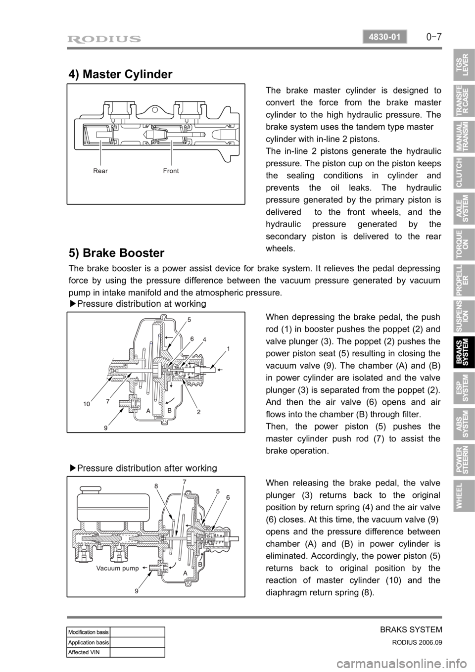
4) Master Cylinder
The brake master cylinder is designed to
convert the force from the brake maste
r
cylinder to the high hydraulic pressure. The
brake system uses the tandem type master
cylinder with in-line 2 pistons.
The in-line 2 pistons generate the hydraulic
pressure. The piston cup on the piston keeps
the sealing conditions in cylinder and
prevents the oil leaks. The hydraulic
pressure generated by the primary piston is
delivered to the front wheels, and the
hydraulic pressure generated by the
secondary piston is delivered to the rea
r
wheels.
5) Brake Booster
The brake booster is a power assist device for brake system. It relieves the pedal depressing
force by using the pressure difference between the vacuum pressure generated by vacuum
pump in intake manifold and the atmospheric pressure.
▶Pressure distribution at working
When depressing the brake pedal, the push
rod (1) in booster pushes the poppet (2) and
valve plunger (3). The poppet (2) pushes the
power piston seat (5) resulting in closing the
vacuum valve (9). The chamber (A) and (B)
in power cylinder are isolated and the valve
plunger (3) is separated from the poppet (2).
And then the air valve (6) opens and ai
r
flows into the chamber (B) through filter.
Then, the power piston (5) pushes the
master cylinder push rod (7) to assist the
brake operation.
▶Pressure distribution after working
When releasing the brake pedal, the valve
plunger (3) returns back to the original
position by return spring (4) and the air valve
(6) closes. At this time, the vacuum valve (9)
opens and the pressure difference between
chamber (A) and (B) in power cylinder is
eliminated. Accordingly, the power piston (5)
returns back to original position by the
reaction of master cylinder (10) and the
diaphragm return spring (8).
Page 375 of 465
0-3
AIR CONDITIONING SYSTEM
RODIUS 2006.09
6810-20
6910-20AIR CONDITIONING SYSTEM
1. FFH SPECIFICATION
Page 376 of 465
0-4
RODIUS 2006.09
6810-20
AIR CONDITIONING SYSTEM
2. SYSTEM LAYOUT AND COMPONENTS
Front air conditioner module assembly - inside instrument panel
Page 377 of 465
0-5
AIR CONDITIONING SYSTEM
RODIUS 2006.09
6810-20
Rear air conditioner module assembly - bottom of rear left
Page 378 of 465
0-6
RODIUS 2006.09
6810-20
AIR CONDITIONING SYSTEM
3. FFF GENERAL INFORMATION
The system is to increase the coolant temperature quickly by firing diesel fuel in the burner that
is installed in engine cooling system when in winter time the ambient temperature and engine
coolant temperature is low. (Option)
FFH System consists of independent fuel lines, fuel pump, coolant circuit, coolant ciculation
pump, electrical glow plug and exhaust system by driver’s intention because FFH system
is automatically.
Operated according to the coolant temperature and the ambient temperature.
FFH system operates up to more than 2 minutes to burn the residual fuel inside the system
when driver stop the engine during its operation. Therefore, a certain period of FFH operation
after stopping the engine is not a malfunction.
Page 379 of 465
0-7
AIR CONDITIONING SYSTEM
RODIUS 2006.09
6810-20
4. COMPONENTS AND LOCATIONS
Page 380 of 465
0-8
RODIUS 2006.09
6810-20
AIR CONDITIONING SYSTEM
1. VENTILATION SYSTEM COMPONENTS
1) Locations of Vents
Front Ventilation
▶
Rear ventilation
▶