Page 316 of 465
0-8
RODIUS 2006.09
4111-01
SUSPENSION SYSTEM
4) rear coil spring
Steel for high tensional spring is adapted.
Maintain more than 20 mm of freeplay when compressed.
Spring seat applied. ·
·
·
▶ Specification
Page 321 of 465

0-7
BRAKS SYSTEM
RODIUS 2006.09
4830-01
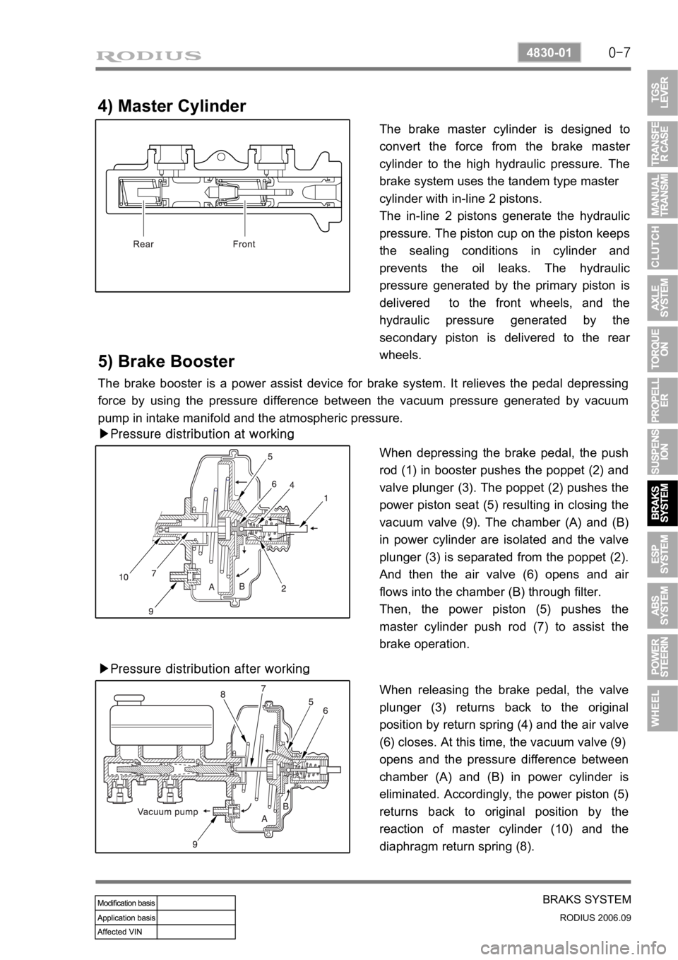
4) Master Cylinder
The brake master cylinder is designed to
convert the force from the brake maste
r
cylinder to the high hydraulic pressure. The
brake system uses the tandem type master
cylinder with in-line 2 pistons.
The in-line 2 pistons generate the hydraulic
pressure. The piston cup on the piston keeps
the sealing conditions in cylinder and
prevents the oil leaks. The hydraulic
pressure generated by the primary piston is
delivered to the front wheels, and the
hydraulic pressure generated by the
secondary piston is delivered to the rea
r
wheels.
5) Brake Booster
The brake booster is a power assist device for brake system. It relieves the pedal depressing
force by using the pressure difference between the vacuum pressure generated by vacuum
pump in intake manifold and the atmospheric pressure.
▶Pressure distribution at working
When depressing the brake pedal, the push
rod (1) in booster pushes the poppet (2) and
valve plunger (3). The poppet (2) pushes the
power piston seat (5) resulting in closing the
vacuum valve (9). The chamber (A) and (B)
in power cylinder are isolated and the valve
plunger (3) is separated from the poppet (2).
And then the air valve (6) opens and ai
r
flows into the chamber (B) through filter.
Then, the power piston (5) pushes the
master cylinder push rod (7) to assist the
brake operation.
▶Pressure distribution after working
When releasing the brake pedal, the valve
plunger (3) returns back to the original
position by return spring (4) and the air valve
(6) closes. At this time, the vacuum valve (9)
opens and the pressure difference between
chamber (A) and (B) in power cylinder is
eliminated. Accordingly, the power piston (5)
returns back to original position by the
reaction of master cylinder (10) and the
diaphragm return spring (8).
Page 322 of 465
0-8
RODIUS 2006.09
4830-01
BRAKS SYSTEM
6) Master Cylider & Booster
ABS system is basically equipped to STAVIC.
Vehicle which adapted ESP system in option has two pressure sensors under master cylinder
and these two sensor are used for BAS (Brake Assist System) system.
Do not disassemble the brake oil pressure sensors These can not be reinstalled of
disassembled.
After reinstall the reserver tank perform a air bleeding of brake system
-
-
Vehicle with ESP Vehicle with ABS
Brake fluid reservoir tank Master cylinder
Page 336 of 465
0-16
RODIUS 2006.09
4892-01
ESP SYSTEM
▶When applied ABS (decreased pressure)
The pressure decreases just before the wheel speed drops and the wheels. The inlet valve
closes and the outlet valve opens as in the ABS HECU and the oil is gathered at the low
pressure chamber while no additional oil is being supplied.
Then the pump operates to allow fast oil drainage.
Page 355 of 465

0-16
RODIUS 2006.09
4892-01
ABS SYSTEM
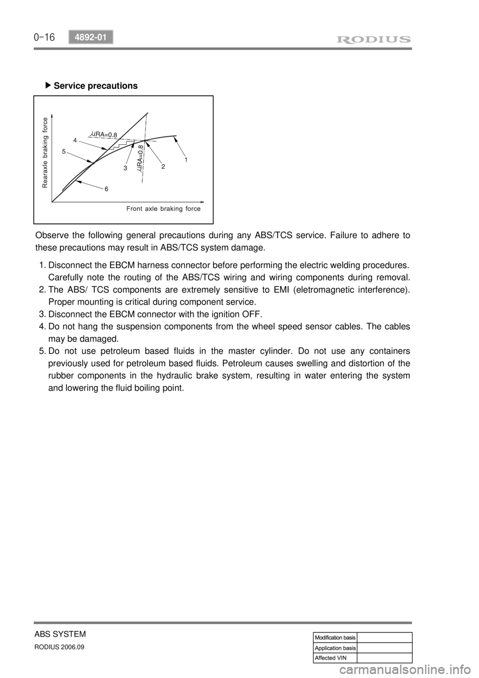
Service precautions ▶
Observe the following general precautions during any ABS/TCS service. Failure to adhere to
these precautions may result in ABS/TCS system damage.
Disconnect the EBCM harness connector before performing the electric welding procedures.
Carefully note the routing of the ABS/TCS wiring and wiring components during removal.
The ABS/ TCS components are extremely sensitive to EMI (eletromagnetic interference).
Proper mounting is critical during component service.
Disconnect the EBCM connector with the ignition OFF.
Do not hang the suspension components from the wheel speed sensor cables. The cables
may be damaged.
Do not use petroleum based fluids in the master cylinder. Do not use any containers
previously used for petroleum based fluids. Petroleum causes swelling and distortion of the
rubber components in the hydraulic brake system, resulting in water entering the system
and lowering the fluid boiling point. 1.
2.
3.
4.
5.
Page 359 of 465

0-20
RODIUS 2006.09
4892-01
ABS SYSTEM
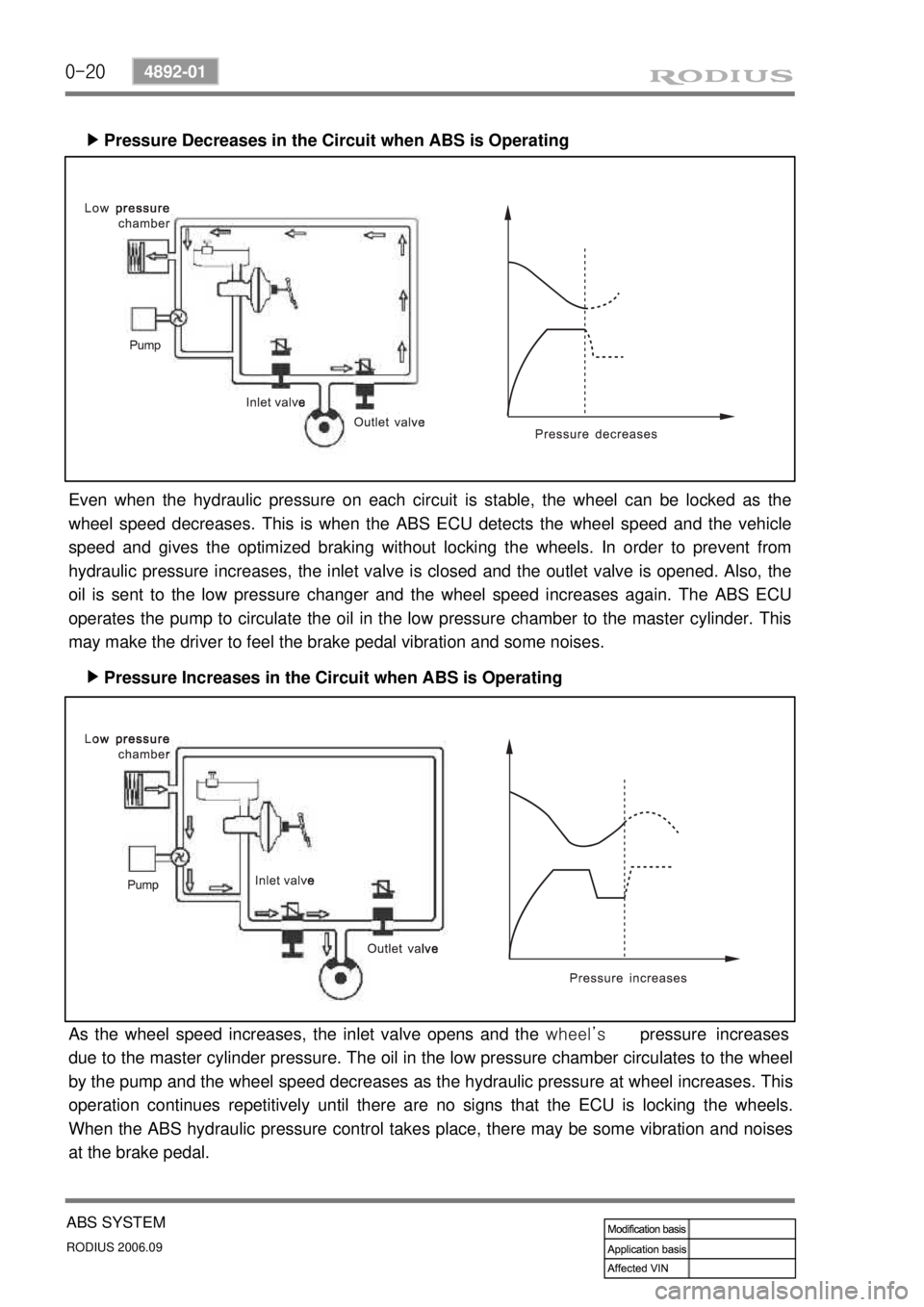
Pressure Decreases in the Circuit when ABS is Operating ▶
Pressure Increases in the Circuit when ABS is Operating ▶
Even when the hydraulic pressure on each circuit is stable, the wheel can be locked as the
wheel speed decreases. This is when the ABS ECU detects the wheel speed and the vehicle
speed and gives the optimized braking without locking the wheels. In order to prevent from
hydraulic pressure increases, the inlet valve is closed and the outlet valve is opened. Also, the
oil is sent to the low pressure changer and the wheel speed increases again. The ABS ECU
operates the pump to circulate the oil in the low pressure chamber to the master cylinder. This
may make the driver to feel the brake pedal vibration and some noises.
As the wheel speed increases, the inlet valve opens and the wheel’s pressure increases
due to the master cylinder pressure. The oil in the low pressure chamber circulates to the wheel
by the pump and the wheel speed decreases as the hydraulic pressure at wheel increases. This
operation continues repetitively until there are no signs that the ECU is locking the wheels.
When the ABS hydraulic pressure control takes place, there may be some vibration and noises
at the brake pedal.
Page 364 of 465
0-5
POWER STEERING SYSTEM
RODIUS 2006.09
4610-00
4. OVERVIEW
The power steering system consists of pump, oil reservoir, rack and pinion gear. The power
steering pump is a vane type and delivers hydraulic pressure to operate the power steering
system. The pressure relief valve in pump controls the discharging pressure.
The rotary valve in rack and pinion gear directs the oil from the power steering pump to one
side of rack piston.
The integrated rack piston converts the hydraulic pressure to linear movement.
The operating force of rack moves the wheels through tie rod, tie rod end and steering knuckle.
Even though the hydraulic pressure cannot be generated, a driver can steer the vehicle without
power assist but it needs very high steering force.
In this case, the operating force of steering wheel is conveyed to pinion, and the movement o
f
pinion moves the rack through pinion gear combined to rack gear.
5. COMPONENTS
Page 366 of 465
0-7
POWER STEERING SYSTEM
RODIUS 2006.09
4610-00
2. POWER STEERING GEAR BOX ASSEMBLY
The power steering gear consists of power cylinder and control valve.
The power cylinder has cylinder, piston and piston rod. The control valve directs the oil to one
end face of the piston to enhance the steering force.
The control valve controls the directions and operations of power cylinder.
Additionally, the safety check valve is installed so that the system can be operated manually
when the system is defective.