Page 362 of 465
0-3
POWER STEERING SYSTEM
RODIUS 2006.09
4610-00
4610-00POWER STEERING SYSTEM
1. SPECIFICATION
Page 363 of 465
0-4
RODIUS 2006.09
4610-00
POWER STEERING SYSTEM
2. TIGHTENING TORQUE
3. SPECIAL TOOLS AND EQUIPMENT
Page 364 of 465
0-5
POWER STEERING SYSTEM
RODIUS 2006.09
4610-00
4. OVERVIEW
The power steering system consists of pump, oil reservoir, rack and pinion gear. The power
steering pump is a vane type and delivers hydraulic pressure to operate the power steering
system. The pressure relief valve in pump controls the discharging pressure.
The rotary valve in rack and pinion gear directs the oil from the power steering pump to one
side of rack piston.
The integrated rack piston converts the hydraulic pressure to linear movement.
The operating force of rack moves the wheels through tie rod, tie rod end and steering knuckle.
Even though the hydraulic pressure cannot be generated, a driver can steer the vehicle without
power assist but it needs very high steering force.
In this case, the operating force of steering wheel is conveyed to pinion, and the movement o
f
pinion moves the rack through pinion gear combined to rack gear.
5. COMPONENTS
Page 365 of 465
0-6
RODIUS 2006.09
4610-00
POWER STEERING SYSTEM
1. COMPONENTS OF POWER STEERING ASSEMBLY
Page 366 of 465
0-7
POWER STEERING SYSTEM
RODIUS 2006.09
4610-00
2. POWER STEERING GEAR BOX ASSEMBLY
The power steering gear consists of power cylinder and control valve.
The power cylinder has cylinder, piston and piston rod. The control valve directs the oil to one
end face of the piston to enhance the steering force.
The control valve controls the directions and operations of power cylinder.
Additionally, the safety check valve is installed so that the system can be operated manually
when the system is defective.
Page 367 of 465
0-8
RODIUS 2006.09
4610-00
POWER STEERING SYSTEM
3. POWER STEERING PUMP
The vane type pump that is connected to engine by belt is used for the power steering system.
This pump generates and controls a proper hydraulic pressure and flows by using the flow
control valve and pressure relief valve.
The flow control valve regulates the excessive amount of discharging oil. When the steering
wheel is stationary or the oil circuit is blocked, the pressure relief valve returns the ove
r
pressurized oil to the oil reservoir.
4. OIL RESERVOIR
The oil reservoir sends the oil to the power steering pump and receives the oil from the power
steering gear.
The oil level in the reservoir depends on the steering wheel positions. therefore, measure the oil
level when the steering wheel is positioned at straight ahead direction (neutral).
Steering pump Reservoir tank
Page 372 of 465
0-7
WHEEL
RODIUS 2006.09
4710-09
2. TIRE’S ABNORMAL PHENOMENA
1) Standing Wave
2) Hydroplaning
During running the rotating tire repeats
deformation and restoring movement
generated in tread. But when the wheel
rotating speed reaches high, the next
deformation applied to tire before restoring
last deformation so the trembling wave
appears in the tread portion. The lower the
tire pressure the severe the trembling wave
appears during the high speed.
The condition of driving a vehicle fast on the
road surface covered with water can cause
tires to fail to rotate with a good contact on
the surface, so results in remaining them a
float. This is so-called hydroplaning. It
causes brake failure, lower tractive force
and losing the steering performance so it is
very vulnerable condition.
Page 373 of 465

0-8
RODIUS 2006.09
4710-09
WHEEL
3. WHEEL ALIGNMENT
The first responsibility of engineering is to design safe steering and suspension systems. Each
component must be strong enough to with stand and absorb extreme punishment.
Both the steering system and the front and the rear suspension must function geometrically
with the body mass.
The steering and suspension systems require that the front wheels self-return and that the tire
rolling effort and the road friction be held to a negligible force in order to allow the customer to
direct the vehicle with the least effort and the most comfort.
A complete wheel alignment check should include measurements of the rear toe and camber.
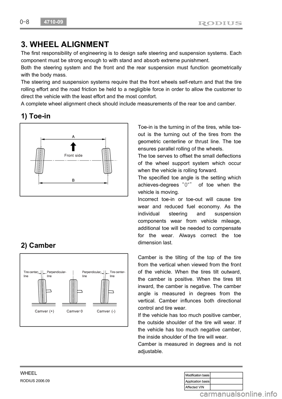
1) Toe-in
2) Camber
Toe-in is the turning in of the tires, while toe-
out is the turning out of the tires from the
geometric centerline or thrust line. The toe
ensures parallel rolling of the wheels.
The toe serves to offset the small deflections
of the wheel support system which occu
r
when the vehicle is rolling forward.
The specified toe angle is the setting which
achieves-degrees “0°” of toe when the
vehicle is moving.
Incorrect toe-in or toe-out will cause tire
wear and reduced fuel economy. As the
individual steering and suspension
components wear from vehicle mileage,
additional toe will be needed to compensate
for the wear. Always correct the toe
dimension last.
Camber is the tilting of the top of the tire
from the vertical when viewed from the front
of the vehicle. When the tires tilt outward,
the camber is positive. When the tires tilt
inward, the camber is negative. The cambe
r
angle is measured in degrees from the
vertical. Camber influnces both directional
control and tire wear.
If the vehicle has too much positive camber,
the outside shoulder of the tire will wear. I
f
the vehicle has too much negative camber,
the inside shoulder of the tire will wear.
Camber is measured in degrees and is not
adjustable.