2007 NISSAN TITAN display
[x] Cancel search: displayPage 5 of 368

Table of
ContentsIllustrated table of contents
Safety—Seats, seat belts and supplemental restraint system
Instruments and controls
Pre-driving checks and adjustments
Display screen, heater, air conditioner and audio systems
Starting and driving
In case of emergency
Appearance and care
Maintenance and do-it-yourself
Technical and consumer information
Index
0
1
2
3
4
5
6
7
8
9
10
Page 77 of 368

SUPPLEMENTAL AIR BAG
WARNING LABELS
Warning labels about the supplemental front air
bags and supplemental side-impact and rollover
air bags are placed in the vehicle as shown in the
illustration.
SUPPLEMENTAL AIR BAG
WARNING LIGHT
The supplemental air bag warning light,
displayingin the instrument panel, moni-
tors the circuits of the supplemental front air bag,
supplemental side air bag and curtain side-
impact and rollover air bag and pre-tensioner
seat belt systems. The circuits monitored by the
supplemental air bag warning light are the diag-
nosis sensor unit, crash zone sensor, satellite
sensors, rollover sensor, front air bag modules,
side air bag modules, curtain air bag modules,
pre-tensioner seat belts and all related wiring.When the ignition key is in the ON or START
position, the supplemental air bag warning light
illuminates for about 7 seconds and then turns
off. This means the system is operational.
If any of the following conditions occur, the
supplemental front air bag, supplemental side air
bag, curtain air bag and pre-tensioner seat belt
systems need servicing:
cThe supplemental air bag warning light re-
mains on after approximately 7 seconds.
cThe supplemental air bag warning light
flashes intermittently.
cThe supplemental air bag warning light does
not come on at all.
Under these conditions, the supplemental front
air bag, supplemental side air bags and curtain air
bag or pre-tensioner seat belt systems may not
operate properly. It must be checked and re-
paired. Take your vehicle to the nearest NISSAN
dealer.
LRS0100
Safety—Seats, seat belts and supplemental restraint system1-61
ZREVIEW COPYÐ2007 Titan(tzw)
Owners ManualÐUSA_English(nna)
07/09/06Ðtbrooks
X
Page 80 of 368

2 Instruments and controls
Instrument panel...................................2-2
Meters and gauges................................2-4
Speedometer and odometer.....................2-4
Tachometer....................................2-5
Engine coolant temperature gauge...............2-6
Fuel gauge....................................2-6
Engine oil pressure gauge.......................2-7
Voltmeter......................................2-8
Automatic transmission fluid temperature
gauge (if so equipped)..........................2-8
Compass and outside temperature display
(if so equipped)...................................2-9
Outside temperature display.....................2-9
Compass display..............................2-10
Warning/indicator lights and audible reminders......2-12
Checking bulbs...............................2-13
Warning lights................................2-13
Indicator lights................................2-17
Audible reminders.............................2-20
Security systems (if so equipped)..................2-20
Vehicle security system.........................2-20
NISSAN vehicle immobilizer system.............2-22
Windshield wiper and washer switch...............2-23Switch operation..............................2-23
Rear window and outside mirror defroster switch
(if so equipped)..................................2-24
Headlight and turn signal switch....................2-25
Headlight control switch........................2-25
Daytime running light system (Canada only)......2-27
Instrument brightness control...................2-28
Turn signal switch.............................2-28
Fog light switch (if so equipped)................2-28
Hazard warning flasher switch.....................2-29
Cargo lamp switch...............................2-29
Horn............................................2-30
Heated seat (if so equipped).......................2-30
Vehicle dynamic control (VDC) off switch
(if so equipped)..................................2-31
Electronic locking rear differential (E-Lock) system
switch (if so equipped)............................2-31
Rear sonar system off switch (if so equipped)........2-32
Tow mode switch.................................2-33
Power outlet.....................................2-33
Cigarette lighter..................................2-35
Storage.........................................2-35
Instrument panel storage trays..................2-35
ZREVIEW COPYÐ2007 Titan(tzw)
Owners ManualÐUSA_English(nna)
07/09/06Ðtbrooks
X
Page 84 of 368

1. Warning/indicator lights
2. Tachometer
3. Speedometer
4. Engine coolant temperature gauge
5. Fuel gauge
6. Engine oil pressure gauge7. Automatic transmission fluid tempera-
ture gauge (if so equipped)
8. Odometer/Twin trip odometer
9. Voltmeter1. Speedometer
2. Odometer/twin trip display
3. Change button
SPEEDOMETER AND ODOMETER
Speedometer
The speedometer indicates vehicle speed in
miles per hour (MPH) and kilometers per hour
(km/h) .
Odometer/Twin trip odometer
The odometer/twin trip odometer is displayed
when the ignition key is in the ON position.
LIC0540
LIC0541
METERS AND GAUGES
2-4Instruments and controls
ZREVIEW COPYÐ2007 Titan(tzw)
Owners ManualÐUSA_English(nna)
07/09/06Ðtbrooks
X
Page 85 of 368

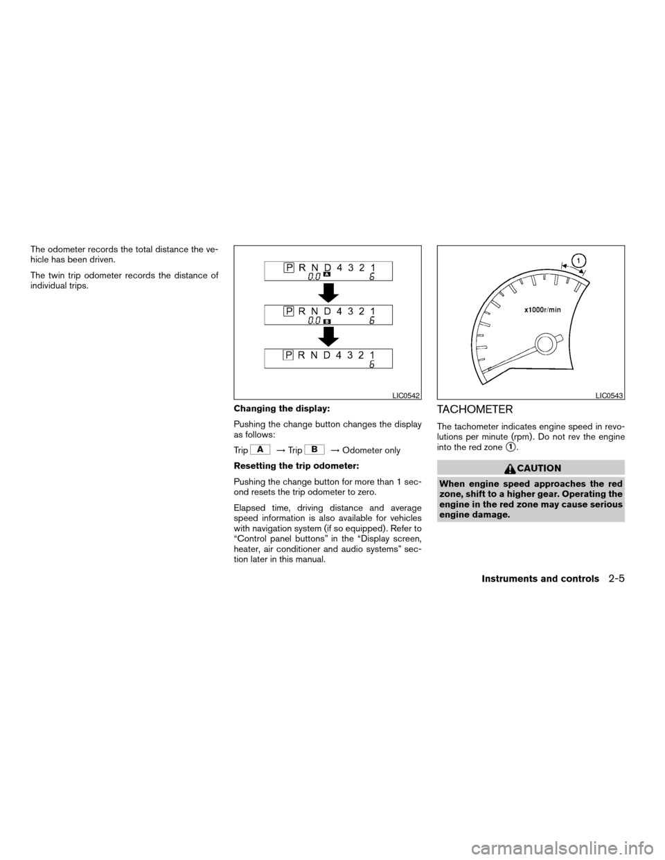
The odometer records the total distance the ve-
hicle has been driven.
The twin trip odometer records the distance of
individual trips.
Changing the display:
Pushing the change button changes the display
as follows:
Trip
!Trip!Odometer only
Resetting the trip odometer:
Pushing the change button for more than 1 sec-
ond resets the trip odometer to zero.
Elapsed time, driving distance and average
speed information is also available for vehicles
with navigation system (if so equipped) . Refer to
“Control panel buttons” in the “Display screen,
heater, air conditioner and audio systems” sec-
tion later in this manual.
TACHOMETER
The tachometer indicates engine speed in revo-
lutions per minute (rpm) . Do not rev the engine
into the red zone
s1.
CAUTION
When engine speed approaches the red
zone, shift to a higher gear. Operating the
engine in the red zone may cause serious
engine damage.
LIC0542LIC0543
Instruments and controls2-5
ZREVIEW COPYÐ2007 Titan(tzw)
Owners ManualÐUSA_English(nna)
07/09/06Ðtbrooks
X
Page 89 of 368

This unit has the following functions:
cMeasures terrestrial magnetism and indi-
cates heading direction of vehicle
cIndicates outside air temperature
cIndicates possible frozen road conditions
With the ignition switch in the ON position, press
the mode button as described in the chart below
to activate various features of the compass and
outside temperature display.
Push and hold
the mode button
for about:Feature:
(Push button again for about 1 sec-
ond to change settings)
1 secondCompass display toggles: °F!°C
!OFF!°F
5 secondsCompass zone can be changed to
correct false compass readings
10 seconds Compass enters calibration mode
OUTSIDE TEMPERATURE DISPLAY
Push the mode buttons1when the ignition key is
in the ON position to change the display as
follows: °F!°C!OFF!°F.
cIf the outside temperature drops below 37°F
(3°C) , the display indicates ICE. The display
will continue to indicate ICE until the tem-
perature reaches 41°F (5°C) .
cWhen the outside temperature is between
130°F (55°C) and 158°F (70°C) , the display
shows 130°F (55°C) .cWhen the outside temperature is between
-22°F (-30°C) and -40°F (-40°C) , the dis-
play shows -22°F (-30°C) .
cWhen the outside temperature is lower than
-40°F (-40°C) or higher than 158°F (70°C) ,
the display shows only———though it is
operating. This is not a malfunction.
cThe outside temperature sensor is located in
front of the radiator. The sensor may be
affected by road or engine heat, wind direc-
tion and other driving conditions. The display
may differ from the actual outside tempera-
ture or the temperature displayed on various
signs or billboards.
Type A
LIC0659
Type B
LIC0660
COMPASS AND OUTSIDE
TEMPERATURE DISPLAY (if so
equipped)
Instruments and controls2-9
ZREVIEW COPYÐ2007 Titan(tzw)
Owners ManualÐUSA_English(nna)
07/09/06Ðtbrooks
X
Page 90 of 368

cTemperature display will not increase unless
the vehicle is moving faster than 12 mph (20
km/h) .
cIf the ignition has been off for less than 2
hours and the outside temperature is greater
than the last detected temperature, the dis-
play will show the last detected temperature
when the ignition is turned on.
COMPASS DISPLAY
Push the mode buttons1when the ignition key is
in the ON position to turn on the compass dis-
play. The arrow
s2indicates direction.
N: North
E: East
S: South
W: West
If the compass display flashes, calibrate the com-
pass by driving the vehicle one and a half circles
at a maximum speed of 6 MPH (10 km/h) .
You can also calibrate the compass by driving
your vehicle on your everyday route. The com-
pass will be calibrated once it has tracked one
and a half circles.
WIC0355
2-10Instruments and controls
ZREVIEW COPYÐ2007 Titan(tzw)
Owners ManualÐUSA_English(nna)
07/09/06Ðtbrooks
X
Page 91 of 368

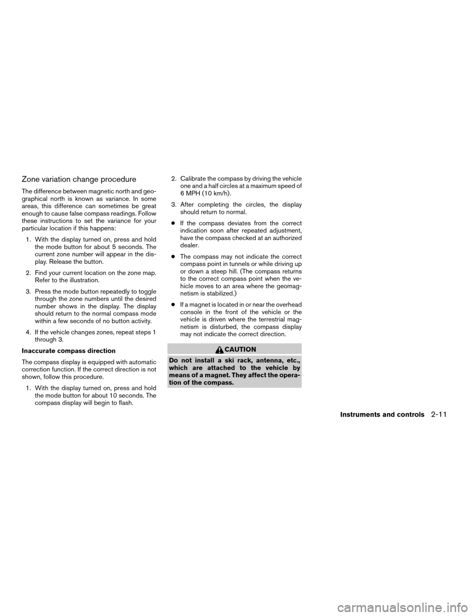
Zone variation change procedure
The difference between magnetic north and geo-
graphical north is known as variance. In some
areas, this difference can sometimes be great
enough to cause false compass readings. Follow
these instructions to set the variance for your
particular location if this happens:
1. With the display turned on, press and hold
the mode button for about 5 seconds. The
current zone number will appear in the dis-
play. Release the button.
2. Find your current location on the zone map.
Refer to the illustration.
3. Press the mode button repeatedly to toggle
through the zone numbers until the desired
number shows in the display. The display
should return to the normal compass mode
within a few seconds of no button activity.
4. If the vehicle changes zones, repeat steps 1
through 3.
Inaccurate compass direction
The compass display is equipped with automatic
correction function. If the correct direction is not
shown, follow this procedure.
1. With the display turned on, press and hold
the mode button for about 10 seconds. The
compass display will begin to flash.2. Calibrate the compass by driving the vehicle
one and a half circles at a maximum speed of
6 MPH (10 km/h) .
3. After completing the circles, the display
should return to normal.
cIf the compass deviates from the correct
indication soon after repeated adjustment,
have the compass checked at an authorized
dealer.
cThe compass may not indicate the correct
compass point in tunnels or while driving up
or down a steep hill. (The compass returns
to the correct compass point when the ve-
hicle moves to an area where the geomag-
netism is stabilized.)
cIf a magnet is located in or near the overhead
console in the front of the vehicle or the
vehicle is driven where the terrestrial mag-
netism is disturbed, the compass display
may not indicate the correct direction.
CAUTION
Do not install a ski rack, antenna, etc.,
which are attached to the vehicle by
means of a magnet. They affect the opera-
tion of the compass.
Instruments and controls2-11
ZREVIEW COPYÐ2007 Titan(tzw)
Owners ManualÐUSA_English(nna)
07/09/06Ðtbrooks
X