2007 NISSAN TIIDA EC Engine Control System
[x] Cancel search: EC Engine Control SystemPage 1355 of 5883

EC-6
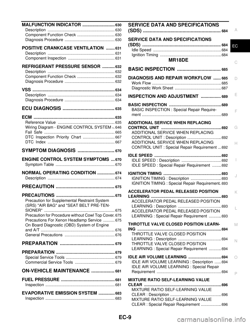
IDLE AIR VOLUME LEARNING : Special Repair
Requirement ..........................................................
390
MIXTURE RATIO SELF-LEARNING VALUE
CLEAR .....................................................................
392
MIXTURE RATIO SELF-LEARNING VALUE
CLEAR : Description ..............................................
392
MIXTURE RATIO SELF-LEARNING VALUE
CLEAR : Special Repair Requirement ...................
392
FUNCTION DIAGNOSIS ............................393
ENGINE CONTROL SYSTEM .........................393
System Diagram ...................................................393
System Description ................................................394
Component Parts Location ..................................394
Component Description .........................................399
MULTIPORT FUEL INJECTION SYSTEM ......401
System Diagram ...................................................401
System Description ................................................401
Component Parts Location ..................................404
Component Description .........................................409
ELECTRIC IGNITION SYSTEM .......................410
System Diagram ...................................................410
System Description ................................................410
Component Parts Location ..................................411
Component Description .........................................416
AIR CONDITIONING CUT CONTROL ............417
System Diagram ....................................................417
System Description ................................................417
Component Parts Location ..................................418
Component Description .........................................423
AUTOMATIC SPEED CONTROL DEVICE
(ASCD) .............................................................
424
System Diagram ....................................................424
System Description ................................................424
Component Parts Location ..................................426
Component Description ........................................431
CAN COMMUNICATION .................................432
System Description ................................................432
COOLING FAN CONTROL .............................433
System Diagram ....................................................433
System Description ................................................433
Component Parts Location ..................................435
Component Description .........................................440
EVAPORATIVE EMISSION SYSTEM .............441
System Diagram ....................................................441
System Description ................................................443
Component Parts Location ..................................444
Component Description ........................................449
INTAKE VALVE TIMING CONTROL ...............450
System Diagram ....................................................450
System Description ................................................450
Component Parts Location ..................................451
Component Description ........................................456
DIAGNOSIS SYSTEM (ECM) ...........................457
Diagnosis Description ...........................................457
CONSULT-III Function ..........................................462
COMPONENT DIAGNOSIS ......................469
TROUBLE DIAGNOSIS - SPECIFICATION
VALUE ..............................................................
469
Description ............................................................469
Component Function Check .................................469
Diagnosis Procedure .............................................470
POWER SUPPLY AND GROUND CIRCUIT ....477
Diagnosis Procedure .............................................477
U1000, U1001 CAN COMM CIRCUIT ..............481
Description ............................................................481
DTC Logic .............................................................481
Diagnosis Procedure .............................................481
U1010 CONTROL UNIT (CAN) ........................482
Description ............................................................482
DTC Logic .............................................................482
Diagnosis Procedure .............................................482
P0011 IVT CONTROL ......................................483
DTC Logic .............................................................483
Component Function Check .................................484
Diagnosis Procedure .............................................484
Component Inspection ..........................................486
P0102, P0103 MAF SENSOR ..........................487
Description ............................................................487
DTC Logic .............................................................487
Diagnosis Procedure .............................................488
Component Inspection ..........................................489
P0117, P0118 ECT SENSOR ...........................492
Description ............................................................492
DTC Logic .............................................................492
Diagnosis Procedure .............................................493
Component Inspection ..........................................493
P0122, P0123 TP SENSOR ..............................495
Description ............................................................495
DTC Logic .............................................................495
Diagnosis Procedure .............................................495
Component Inspection ..........................................497
Special Repair Requirement .................................497
P0132 HO2S1 ...................................................498
Description ............................................................498
DTC Logic .............................................................498
Diagnosis Procedure .............................................499
Component Inspection ..........................................500
P0134 HO2S1 ...................................................502
Description ............................................................502
DTC Logic .............................................................502
Page 1358 of 5883

EC-9
C
D
E
F
G
H
I
J
K
L
M
ECA
N
O
P
MALFUNCTION INDICATOR ...........................630
Description ............................................................630
Component Function Check ..................................630
Diagnosis Procedure .............................................630
POSITIVE CRANKCASE VENTILATION ........631
Description ............................................................631
Component Inspection ..........................................631
REFRIGERANT PRESSURE SENSOR ...........632
Description ............................................................632
Component Function Check ..................................632
Diagnosis Procedure .............................................632
VSS ...................................................................634
Description ............................................................634
Diagnosis Procedure .............................................634
ECU DIAGNOSIS .......................................635
ECM ..................................................................635
Reference Value ...................................................635
Wiring Diagram - ENGINE CONTROL SYSTEM - ..646
Fail Safe ...............................................................665
DTC Inspection Priority Chart .............................667
DTC Index ............................................................667
SYMPTOM DIAGNOSIS ............................670
ENGINE CONTROL SYSTEM SYMPTOMS ....670
Symptom Table .....................................................670
NORMAL OPERATING CONDITION ...............674
Description ............................................................674
PRECAUTION ............................................675
PRECAUTIONS ................................................675
Precaution for Supplemental Restraint System
(SRS) "AIR BAG" and "SEAT BELT PRE-TEN-
SIONER" ...............................................................
675
Precaution for Procedure without Cowl Top Cover ..675
Precautions For Xenon Headlamp Service ...........675
On Board Diagnostic (OBD) System of Engine
and A/T ..................................................................
676
General Precautions .............................................676
PREPARATION .........................................679
PREPARATION ................................................679
Special Service Tools ............................................679
Commercial Service Tools ....................................679
ON-VEHICLE MAINTENANCE ..................681
FUEL PRESSURE ............................................681
Inspection ..............................................................681
EVAPORATIVE EMISSION SYSTEM ..............683
Inspection ..............................................................683
SERVICE DATA AND SPECIFICATIONS
(SDS) ..........................................................
684
SERVICE DATA AND SPECIFICATIONS
(SDS) ...............................................................
684
Idle Speed .............................................................684
Ignition Timing .......................................................684
MR18DE
BASIC INSPECTION .................................
685
DIAGNOSIS AND REPAIR WORKFLOW ......685
Work Flow ..............................................................685
Diagnostic Work Sheet ..........................................687
INSPECTION AND ADJUSTMENT ................689
BASIC INSPECTION ...............................................689
BASIC INSPECTION : Special Repair Require-
ment .......................................................................
689
ADDITIONAL SERVICE WHEN REPLACING
CONTROL UNIT ......................................................
692
ADDITIONAL SERVICE WHEN REPLACING
CONTROL UNIT : Description ...............................
692
ADDITIONAL SERVICE WHEN REPLACING
CONTROL UNIT : Special Repair Requirement ....
692
IDLE SPEED ............................................................692
IDLE SPEED : Description ....................................692
IDLE SPEED : Special Repair Requirement .........692
IGNITION TIMING ....................................................693
IGNITION TIMING : Description ............................693
IGNITION TIMING : Special Repair Requirement ..693
ACCELERATOR PEDAL RELEASED POSITION
LEARNING ...............................................................
693
ACCELERATOR PEDAL RELEASED POSITION
LEARNING : Description .......................................
693
ACCELERATOR PEDAL RELEASED POSITION
LEARNING : Special Repair Requirement ............
693
THROTTLE VALVE CLOSED POSITION LEARN-
ING ...........................................................................
694
THROTTLE VALVE CLOSED POSITION
LEARNING : Description .......................................
694
THROTTLE VALVE CLOSED POSITION
LEARNING : Special Repair Requirement ............
694
IDLE AIR VOLUME LEARNING ..............................694
IDLE AIR VOLUME LEARNING : Description .......694
IDLE AIR VOLUME LEARNING : Special Repair
Requirement ..........................................................
694
MIXTURE RATIO SELF-LEARNING VALUE
CLEAR .....................................................................
696
MIXTURE RATIO SELF-LEARNING VALUE
CLEAR : Description ..............................................
696
MIXTURE RATIO SELF-LEARNING VALUE
CLEAR : Special Repair Requirement ...................
696
Page 1359 of 5883

EC-10
FUNCTION DIAGNOSIS ............................697
ENGINE CONTROL SYSTEM .........................697
System Diagram ...................................................697
System Description ................................................698
Component Parts Location ..................................698
Component Description .........................................703
MULTIPORT FUEL INJECTION SYSTEM ......705
System Diagram ...................................................705
System Description ................................................705
Component Parts Location ..................................708
Component Description .........................................713
ELECTRIC IGNITION SYSTEM .......................714
System Diagram ...................................................714
System Description ................................................714
Component Parts Location ..................................715
Component Description .........................................720
AIR CONDITIONING CUT CONTROL ............721
System Diagram ....................................................721
System Description ................................................721
Component Parts Location ..................................722
Component Description .........................................727
AUTOMATIC SPEED CONTROL DEVICE
(ASCD) .............................................................
728
System Diagram ....................................................728
System Description ................................................728
Component Parts Location ..................................730
Component Description ........................................735
CAN COMMUNICATION .................................736
System Description ................................................736
COOLING FAN CONTROL .............................737
System Diagram ....................................................737
System Description ................................................737
Component Parts Location ..................................739
Component Description .........................................744
EVAPORATIVE EMISSION SYSTEM .............745
System Diagram ....................................................745
System Description ................................................746
Component Parts Location ..................................747
Component Description ........................................752
INTAKE VALVE TIMING CONTROL ...............753
System Diagram ....................................................753
System Description ................................................753
Component Parts Location ..................................754
Component Description .........................................759
ON BOARD DIAGNOSTIC (OBD) SYSTEM ...760
Diagnosis Description ............................................760
CONSULT-III Function ..........................................772
Diagnosis Tool Function ......................................779
COMPONENT DIAGNOSIS .......................781
TROUBLE DIAGNOSIS - SPECIFICATION
VALUE ..............................................................
781
Description ............................................................781
Component Function Check .................................781
Diagnosis Procedure .............................................782
POWER SUPPLY AND GROUND CIRCUIT ....789
Diagnosis Procedure .............................................789
U1000, U1001 CAN COMM CIRCUIT ..............793
Description ............................................................793
DTC Logic .............................................................793
Diagnosis Procedure .............................................793
U1010 CONTROL UNIT (CAN) ........................794
Description ............................................................794
DTC Logic .............................................................794
Diagnosis Procedure .............................................794
P0011 IVT CONTROL ......................................795
DTC Logic .............................................................795
Diagnosis Procedure .............................................796
Component Inspection ..........................................797
P0102, P0103 MAF SENSOR ..........................799
Description ............................................................799
DTC Logic .............................................................799
Diagnosis Procedure .............................................800
Component Inspection ..........................................801
P0112, P0113 IAT SENSOR ............................804
Description ............................................................804
DTC Logic .............................................................804
Diagnosis Procedure .............................................805
Component Inspection ..........................................805
P0117, P0118 ECT SENSOR ...........................807
Description ............................................................807
DTC Logic .............................................................807
Diagnosis Procedure .............................................808
Component Inspection ..........................................808
P0122, P0123 TP SENSOR ..............................810
Description ............................................................810
DTC Logic .............................................................810
Diagnosis Procedure .............................................810
Component Inspection ..........................................812
Special Repair Requirement .................................812
P0132 HO2S1 ...................................................813
Description ............................................................813
DTC Logic .............................................................813
Diagnosis Procedure .............................................814
Component Inspection ..........................................815
P0133 HO2S1 ...................................................817
Description ............................................................817
DTC Logic .............................................................817
Diagnosis Procedure .............................................819
Component Inspection ..........................................820
Page 1362 of 5883

EC-13
C
D
E
F
G
H
I
J
K
L
M
ECA
N
O
P
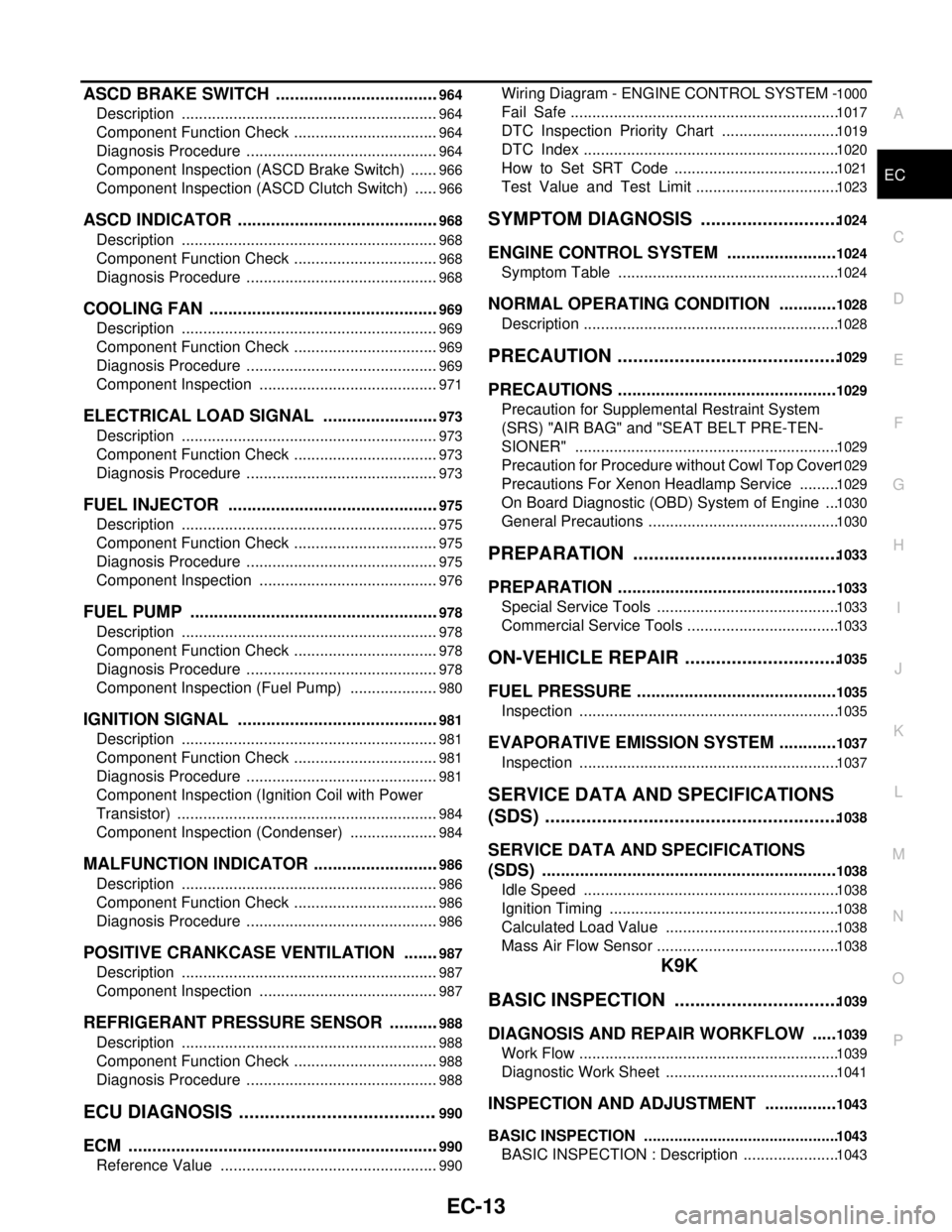
ASCD BRAKE SWITCH ...................................964
Description ............................................................964
Component Function Check ..................................964
Diagnosis Procedure .............................................964
Component Inspection (ASCD Brake Switch) .......966
Component Inspection (ASCD Clutch Switch) ......966
ASCD INDICATOR ...........................................968
Description ............................................................968
Component Function Check ..................................968
Diagnosis Procedure .............................................968
COOLING FAN .................................................969
Description ............................................................969
Component Function Check ..................................969
Diagnosis Procedure .............................................969
Component Inspection ..........................................971
ELECTRICAL LOAD SIGNAL .........................973
Description ............................................................973
Component Function Check ..................................973
Diagnosis Procedure .............................................973
FUEL INJECTOR .............................................975
Description ............................................................975
Component Function Check ..................................975
Diagnosis Procedure .............................................975
Component Inspection ..........................................976
FUEL PUMP .....................................................978
Description ............................................................978
Component Function Check ..................................978
Diagnosis Procedure .............................................978
Component Inspection (Fuel Pump) .....................980
IGNITION SIGNAL ...........................................981
Description ............................................................981
Component Function Check ..................................981
Diagnosis Procedure .............................................981
Component Inspection (Ignition Coil with Power
Transistor) .............................................................
984
Component Inspection (Condenser) .....................984
MALFUNCTION INDICATOR ...........................986
Description ............................................................986
Component Function Check ..................................986
Diagnosis Procedure .............................................986
POSITIVE CRANKCASE VENTILATION ........987
Description ............................................................987
Component Inspection ..........................................987
REFRIGERANT PRESSURE SENSOR ...........988
Description ............................................................988
Component Function Check ..................................988
Diagnosis Procedure .............................................988
ECU DIAGNOSIS .......................................990
ECM ..................................................................990
Reference Value ...................................................990
Wiring Diagram - ENGINE CONTROL SYSTEM - 1000
Fail Safe ..............................................................1017
DTC Inspection Priority Chart ...........................1019
DTC Index ...........................................................1020
How to Set SRT Code ......................................1021
Test Value and Test Limit .................................1023
SYMPTOM DIAGNOSIS ...........................1024
ENGINE CONTROL SYSTEM .......................1024
Symptom Table ...................................................1024
NORMAL OPERATING CONDITION ............1028
Description ...........................................................1028
PRECAUTION ...........................................1029
PRECAUTIONS ..............................................1029
Precaution for Supplemental Restraint System
(SRS) "AIR BAG" and "SEAT BELT PRE-TEN-
SIONER" .............................................................
1029
Precaution for Procedure without Cowl Top Cover 1029
Precautions For Xenon Headlamp Service .........1029
On Board Diagnostic (OBD) System of Engine ...1030
General Precautions ............................................1030
PREPARATION ........................................1033
PREPARATION ..............................................1033
Special Service Tools ..........................................1033
Commercial Service Tools ...................................1033
ON-VEHICLE REPAIR ..............................1035
FUEL PRESSURE ..........................................1035
Inspection ............................................................1035
EVAPORATIVE EMISSION SYSTEM ............1037
Inspection ............................................................1037
SERVICE DATA AND SPECIFICATIONS
(SDS) .........................................................
1038
SERVICE DATA AND SPECIFICATIONS
(SDS) ..............................................................
1038
Idle Speed ...........................................................1038
Ignition Timing .....................................................1038
Calculated Load Value ........................................1038
Mass Air Flow Sensor ..........................................1038
K9K
BASIC INSPECTION ................................
1039
DIAGNOSIS AND REPAIR WORKFLOW .....1039
Work Flow ............................................................1039
Diagnostic Work Sheet ........................................1041
INSPECTION AND ADJUSTMENT ...............1043
BASIC INSPECTION .............................................1043
BASIC INSPECTION : Description ......................1043
Page 1363 of 5883

EC-14
BASIC INSPECTION : Special Repair Require-
ment (TEST 1: Low Pressure Fuel Supply System
Check) .................................................................
1043
BASIC INSPECTION : Special Repair Require-
ment (TEST 2: Internal Fuel Transfer Pump
Check) .................................................................
1044
BASIC INSPECTION : Special Repair Require-
ment [TEST 3: High Pressure Supply Pump (Pres-
sure Control Valve) Check] ..................................
1044
BASIC INSPECTION : Special Repair Require-
ment [TEST 4: High Pressure Supply Pump (Vol-
umetric Control Valve) Check] .............................
1045
BASIC INSPECTION : Special Repair Require-
ment (TEST 5: Rail High Pressure Regulation
Check) .................................................................
1048
BASIC INSPECTION : Special Repair Require-
ment (TEST 6: Major Leak in Fuel Injectors/Fuel
Injectors Open) ....................................................
1052
BASIC INSPECTION : Special Repair Require-
ment (TEST 7: Incorrect Fuel Injection Quantity)
1053
ADDITIONAL SERVICE WHEN REPLACING
CONTROL UNIT .....................................................
1054
ADDITIONAL SERVICE WHEN REPLACING
CONTROL UNIT : Description .............................
1054
ADDITIONAL SERVICE WHEN REPLACING
CONTROL UNIT : Special Repair Requirement ..
1054
EGR VOLUME CONTROL VALVE CLOSED POSI-
TION LEARNING ...................................................
1055
EGR VOLUME CONTROL VALVE CLOSED PO-
SITION LEARNING : Description ........................
1055
EGR VOLUME CONTROL VALVE CLOSED PO-
SITION LEARNING : Special Repair Requirement
1055
FUNCTION DIAGNOSIS ..........................1057
ENGINE CONTROL SYSTEM ........................1057
System Diagram ..................................................1057
System Description ..............................................1058
Component Parts Location ..................................1058
Component Description .......................................1062
FUEL INJECTION CONTROL ........................1063
System Description ..............................................1063
Component Parts Location ..................................1065
TURBOCHARGER BOOST CONTROL .........1070
Vacuum Hose Drawing ........................................1070
System Description ..............................................1070
Component Parts Location ..................................1071
EGR SYSTEM .................................................1076
System Description ..............................................1076
Component Parts Location ..................................1076
IDLE SPEED CONTROL ................................1081
System Diagram ..................................................1081
System Description ..............................................1081
Component Parts Location ..................................1082
ENGINE TORQUE CONTROL .......................1087
System Description ..............................................1087
Component Parts Location ..................................1087
GLOW CONTROL ..........................................1092
System Description ..............................................1092
Component Parts Location ..................................1092
COOLING FAN CONTROL ............................1097
System Description ..............................................1097
Component Parts Location ..................................1098
CAN COMMUNICATION ................................1103
System Description ..............................................1103
ON BOARD DIAGNOSTIC (OBD) SYSTEM ..1104
Diagnosis Description ..........................................1104
COMPONENT DIAGNOSIS .....................1106
POWER SUPPLY AND GROUND CIRCUIT ..1106
Diagnosis Procedure ............................................1106
P0001 FUEL PUMP ........................................1109
DTC Logic ............................................................1109
Diagnosis Procedure ............................................1109
Component Inspection .........................................1110
P0002 FUEL PUMP ........................................1111
DTC Logic ............................................................1111
Diagnosis Procedure ............................................1111
Component Inspection .........................................1112
P0016 CKP - CMP CORRELATION ...............1113
DTC Logic ............................................................1113
Diagnosis Procedure ............................................1113
Component Inspection .........................................1114
P0045 TC BOOST CONTROL SOLENOID
VALVE ............................................................
1116
DTC Logic ............................................................1116
Diagnosis Procedure ............................................1116
Component Inspection .........................................1117
P0069 TC BOOST SENSOR, BARO SENSOR
CORRELATION ..............................................
1118
DTC Logic ............................................................1118
Diagnosis Procedure ............................................1118
Component Inspection .........................................1119
P0087 FUEL PUMP ........................................1120
DTC Logic ............................................................1120
Diagnosis Procedure ............................................1120
P0090 FUEL PUMP ........................................1122
DTC Logic ............................................................1122
Diagnosis Procedure ............................................1122
Component Inspection .........................................1123
P0100 MAF SENSOR .....................................1124
Description ...........................................................1124
DTC Logic ............................................................1124
Page 1365 of 5883

EC-16
P0606 ECM .....................................................1178
Description ...........................................................1178
DTC Logic ............................................................1178
Diagnosis Procedure ...........................................1178
P0641 SENSOR POWER SUPPLY ................1180
DTC Logic ............................................................1180
Diagnosis Procedure ...........................................1180
P0651 SENSOR POWER SUPPLY ................1182
DTC Logic ............................................................1182
Diagnosis Procedure ...........................................1182
P0685 ECM RELAY ........................................1184
DTC Logic ............................................................1184
Diagnosis Procedure ...........................................1184
P1089 FUEL PUMP ........................................1186
DTC Logic ............................................................1186
Diagnosis Procedure ...........................................1186
P2101 ELECTRIC THROTTLE CONTROL
FUNCTION ......................................................
1188
Description ...........................................................1188
DTC Logic ............................................................1188
Diagnosis Procedure ...........................................1188
Component Inspection .........................................1189
P2120 APP SENSOR .....................................1191
Description ...........................................................1191
DTC Logic ............................................................1191
Diagnosis Procedure ...........................................1191
Component Inspection .........................................1193
P2226 BARO SENSOR ..................................1194
Description ...........................................................1194
DTC Logic ............................................................1194
Diagnosis Procedure ...........................................1194
P2263 TC SYSTEM ........................................1195
DTC Logic ............................................................1195
Diagnosis Procedure ...........................................1195
P2299 ACCELERATOR/BRAKE PEDAL PO-
SITION INCONSISTENCY ..............................
1198
DTC Logic ............................................................1198
Diagnosis Procedure ...........................................1198
P2413 EGR SYSTEM .....................................1202
DTC Logic ............................................................1202
Diagnosis Procedure ...........................................1202
Component Inspection .........................................1204
P2502 BATTERY VOLTAGE ..........................1205
DTC Logic ............................................................1205
Diagnosis Procedure ...........................................1205
P2610 ENGINE SAFETY STOP .....................1206
DTC Logic ............................................................1206
Diagnosis Procedure ...........................................1206
ASCD CLUTCH SWITCH ...............................1208
Description ...........................................................1208
Component Function Check ................................1208
Diagnosis Procedure ............................................1208
Component Inspection .........................................1209
ASCD INDICATOR .........................................1210
Description ...........................................................1210
Component Function Check ................................1210
Diagnosis Procedure ............................................1210
COOLING FAN ...............................................1211
Description ...........................................................1211
Component Function Check ................................1211
Diagnosis Procedure ............................................1211
Component Inspection .........................................1212
STOP LAMP SWITCH ....................................1214
Description ...........................................................1214
Component Function Check ................................1214
Diagnosis Procedure ............................................1214
Component Inspection .........................................1215
ECU DIAGNOSIS .....................................1216
ECM ................................................................1216
Reference Value ..................................................1216
Conformity Check ................................................1223
Wiring Diagram - ENGINE CONTROL SYSTEM - 1236
DTC Index ............................................................1252
SYMPTOM DIAGNOSIS ..........................1255
ENGINE CONTROL SYSTEM SYMPTOMS ..1255
Symptom Table ....................................................1255
NOT COMMUNICATION WITH THE ECM .....1256
Description ...........................................................1256
Diagnosis Procedure ............................................1256
ENGINE DOES NOT START OR STARTS
WITH DIFFICULTY .........................................
1257
Description ...........................................................1257
Diagnosis Procedure ............................................1257
STARTING DIFFICULT WITH COLD ENGINE 1259
Description ...........................................................1259
Diagnosis Procedure ............................................1259
IMPOSSIBLE TO SHUT OFF ENGINE ..........1261
Description ...........................................................1261
Diagnosis Procedure ............................................1261
ENGINE IDLE SPEED TOO HIGH .................1262
Description ...........................................................1262
Diagnosis Procedure ............................................1262
ENGINE IDLE SPEED TOO LOW OR UNSTA-
BLE .................................................................
1263
Description ...........................................................1263
Diagnosis Procedure ............................................1263
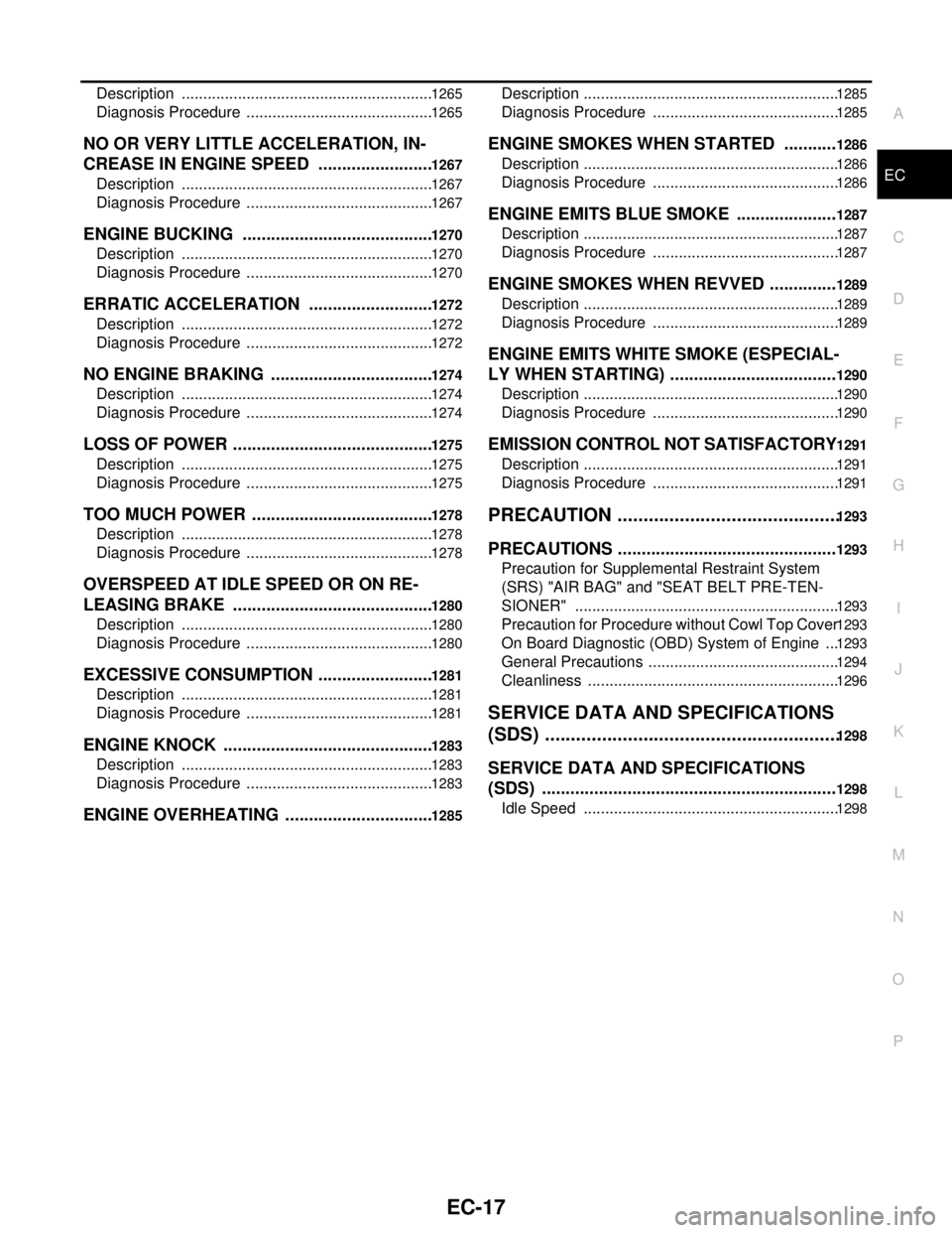
ENGINE STALLING .......................................1265
Page 1366 of 5883

EC-17
C
D
E
F
G
H
I
J
K
L
M
ECA
N
O
P Description ..........................................................
1265
Diagnosis Procedure ...........................................1265
NO OR VERY LITTLE ACCELERATION, IN-
CREASE IN ENGINE SPEED ........................
1267
Description ..........................................................1267
Diagnosis Procedure ...........................................1267
ENGINE BUCKING ........................................1270
Description ..........................................................1270
Diagnosis Procedure ...........................................1270
ERRATIC ACCELERATION ..........................1272
Description ..........................................................1272
Diagnosis Procedure ...........................................1272
NO ENGINE BRAKING ..................................1274
Description ..........................................................1274
Diagnosis Procedure ...........................................1274
LOSS OF POWER ..........................................1275
Description ..........................................................1275
Diagnosis Procedure ...........................................1275
TOO MUCH POWER ......................................1278
Description ..........................................................1278
Diagnosis Procedure ...........................................1278
OVERSPEED AT IDLE SPEED OR ON RE-
LEASING BRAKE ..........................................
1280
Description ..........................................................1280
Diagnosis Procedure ...........................................1280
EXCESSIVE CONSUMPTION ........................1281
Description ..........................................................1281
Diagnosis Procedure ...........................................1281
ENGINE KNOCK ............................................1283
Description ..........................................................1283
Diagnosis Procedure ...........................................1283
ENGINE OVERHEATING ...............................1285
Description ...........................................................1285
Diagnosis Procedure ...........................................1285
ENGINE SMOKES WHEN STARTED ...........1286
Description ...........................................................1286
Diagnosis Procedure ...........................................1286
ENGINE EMITS BLUE SMOKE .....................1287
Description ...........................................................1287
Diagnosis Procedure ...........................................1287
ENGINE SMOKES WHEN REVVED ..............1289
Description ...........................................................1289
Diagnosis Procedure ...........................................1289
ENGINE EMITS WHITE SMOKE (ESPECIAL-
LY WHEN STARTING) ...................................
1290
Description ...........................................................1290
Diagnosis Procedure ...........................................1290
EMISSION CONTROL NOT SATISFACTORY 1291
Description ...........................................................1291
Diagnosis Procedure ...........................................1291
PRECAUTION ...........................................1293
PRECAUTIONS ..............................................1293
Precaution for Supplemental Restraint System
(SRS) "AIR BAG" and "SEAT BELT PRE-TEN-
SIONER" .............................................................
1293
Precaution for Procedure without Cowl Top Cover 1293
On Board Diagnostic (OBD) System of Engine ...1293
General Precautions ............................................1294
Cleanliness ..........................................................1296
SERVICE DATA AND SPECIFICATIONS
(SDS) .........................................................
1298
SERVICE DATA AND SPECIFICATIONS
(SDS) ..............................................................
1298
Idle Speed ...........................................................1298
Page 1376 of 5883
![NISSAN TIIDA 2007 Service Repair Manual INSPECTION AND ADJUSTMENT
EC-27
< BASIC INSPECTION >[HR16DE (WITH EURO-OBD)]
C
D
E
F
G
H
I
J
K
L
MA
EC
N
P O
quirementINFOID:0000000001161131
1.START
1. Make sure that accelerator pedal is fully relea NISSAN TIIDA 2007 Service Repair Manual INSPECTION AND ADJUSTMENT
EC-27
< BASIC INSPECTION >[HR16DE (WITH EURO-OBD)]
C
D
E
F
G
H
I
J
K
L
MA
EC
N
P O
quirementINFOID:0000000001161131
1.START
1. Make sure that accelerator pedal is fully relea](/manual-img/5/57395/w960_57395-1375.png)
INSPECTION AND ADJUSTMENT
EC-27
< BASIC INSPECTION >[HR16DE (WITH EURO-OBD)]
C
D
E
F
G
H
I
J
K
L
MA
EC
N
P O
quirementINFOID:0000000001161131
1.START
1. Make sure that accelerator pedal is fully released.
2. Turn ignition switch ON and wait at least 2 seconds.
3. Turn ignition switch OFF and wait at least 10 seconds.
4. Turn ignition switch ON and wait at least 2 seconds.
5. Turn ignition switch OFF and wait at least 10 seconds.
>> END
THROTTLE VALVE CLOSED POSITION LEARNING
THROTTLE VALVE CLOSED POSITION LEARNING : DescriptionINFOID:0000000001161132
Throttle Valve Closed Position Learning is a function of ECM to learn the fully closed position of the throttle
valve by monitoring the throttle position sensor output signal. It must be performed each time harness connec-
tor of electric throttle control actuator or ECM is disconnected.
THROTTLE VALVE CLOSED POSITION LEARNING : Special Repair Requirement
INFOID:0000000001161133
1.START
1. Make sure that accelerator pedal is fully released.
2. Turn ignition switch ON.
3. Turn ignition switch OFF and wait at least 10 seconds.
Make sure that throttle valve moves during above 10 seconds by confirming the operating sound.
>> END
IDLE AIR VOLUME LEARNING
IDLE AIR VOLUME LEARNING : DescriptionINFOID:0000000001161134
Idle Air Volume Learning is a function of ECM to learn the idle air volume that keeps each engine idle speed
within the specific range. It must be performed under any of the following conditions:
Each time electric throttle control actuator or ECM is replaced.
Idle speed or ignition timing is out of specification.
IDLE AIR VOLUME LEARNING : Special Repair RequirementINFOID:0000000001161135
1.PRECONDITIONING
Make sure that all of the following conditions are satisfied.
Learning will be cancelled if any of the following conditions are missed for even a moment.
Battery voltage: More than 12.9V (At idle)
Engine coolant temperature: 70 - 100°C (158 - 212°F)
Park/neutral position switch: ON
Electric load switch: OFF
(Air conditioner, headlamp, rear window defogger)
On vehicles equipped with daytime light systems, set lighting switch to the 1st position to light only
small lamps.
Steering wheel: Neutral (Straight-ahead position)
Vehicle speed: Stopped
Transmission: Warmed-up
- For A/T models with CONSULT-III
Drive vehicle until “ATF TEMP SE 1” in “DATA MONITOR” mode of “A/T” system indicates less than 0.9V.
- For A/T models without CONSULT-III and M/T models.
Drive vehicle for 10 minutes
Do you have CONSULT-III?
YES >> GO TO 2.