2007 NISSAN TIIDA Electrical control unit
[x] Cancel search: Electrical control unitPage 3238 of 5883
GI-44
< PRECAUTION >
PRECAUTIONS
General Precaution
INFOID:0000000001606118
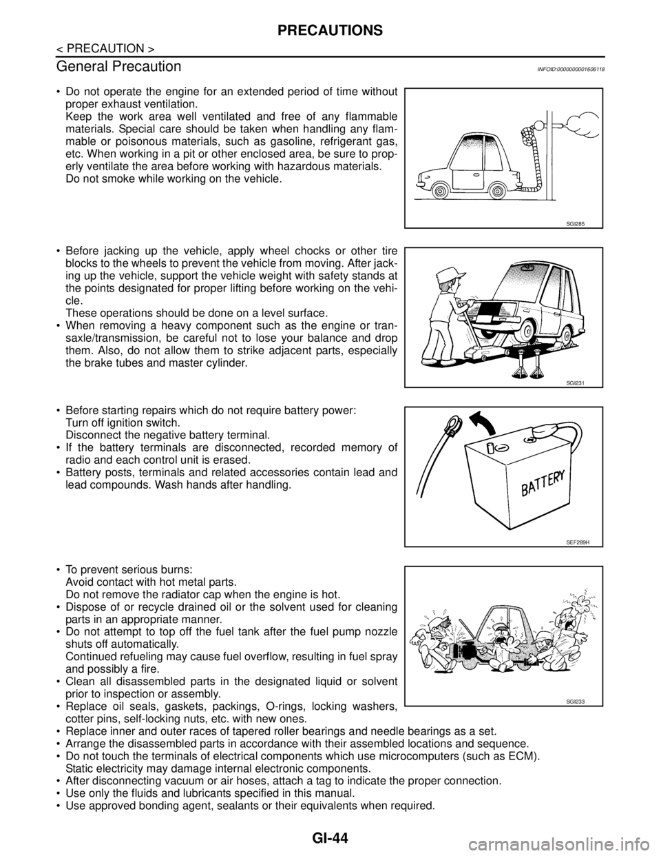
Do not operate the engine for an extended period of time without
proper exhaust ventilation.
Keep the work area well ventilated and free of any flammable
materials. Special care should be taken when handling any flam-
mable or poisonous materials, such as gasoline, refrigerant gas,
etc. When working in a pit or other enclosed area, be sure to prop-
erly ventilate the area before working with hazardous materials.
Do not smoke while working on the vehicle.
Before jacking up the vehicle, apply wheel chocks or other tire
blocks to the wheels to prevent the vehicle from moving. After jack-
ing up the vehicle, support the vehicle weight with safety stands at
the points designated for proper lifting before working on the vehi-
cle.
These operations should be done on a level surface.
When removing a heavy component such as the engine or tran-
saxle/transmission, be careful not to lose your balance and drop
them. Also, do not allow them to strike adjacent parts, especially
the brake tubes and master cylinder.
Before starting repairs which do not require battery power:
Turn off ignition switch.
Disconnect the negative battery terminal.
If the battery terminals are disconnected, recorded memory of
radio and each control unit is erased.
Battery posts, terminals and related accessories contain lead and
lead compounds. Wash hands after handling.
To prevent serious burns:
Avoid contact with hot metal parts.
Do not remove the radiator cap when the engine is hot.
Dispose of or recycle drained oil or the solvent used for cleaning
parts in an appropriate manner.
Do not attempt to top off the fuel tank after the fuel pump nozzle
shuts off automatically.
Continued refueling may cause fuel overflow, resulting in fuel spray
and possibly a fire.
Clean all disassembled parts in the designated liquid or solvent
prior to inspection or assembly.
Replace oil seals, gaskets, packings, O-rings, locking washers,
cotter pins, self-locking nuts, etc. with new ones.
Replace inner and outer races of tapered roller bearings and needle bearings as a set.
Arrange the disassembled parts in accordance with their assembled locations and sequence.
Do not touch the terminals of electrical components which use microcomputers (such as ECM).
Static electricity may damage internal electronic components.
After disconnecting vacuum or air hoses, attach a tag to indicate the proper connection.
Use only the fluids and lubricants specified in this manual.
Use approved bonding agent, sealants or their equivalents when required.
SGI285
SGI231
SEF289H
SGI233
Page 3245 of 5883
SERVICE INFORMATION FOR ELECTRICAL INCIDENT
GI-51
< BASIC INSPECTION >
C
D
E
F
G
H
I
J
K
L
MB
GI
N
O
PBASIC INSPECTION
SERVICE INFORMATION FOR ELECTRICAL INCIDENT
Work FlowINFOID:0000000001691467
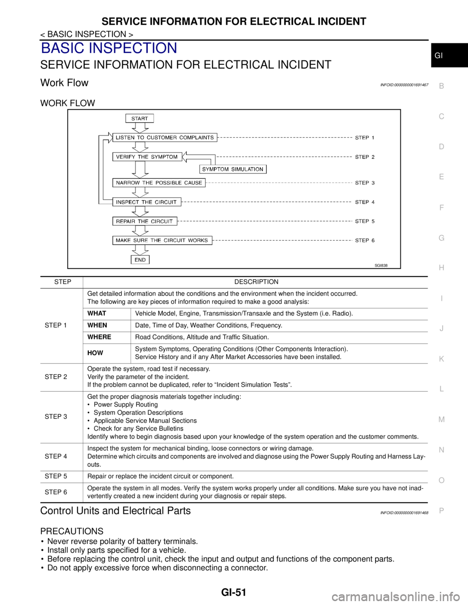
WORK FLOW
Control Units and Electrical PartsINFOID:0000000001691468
PRECAUTIONS
Never reverse polarity of battery terminals.
Install only parts specified for a vehicle.
Before replacing the control unit, check the input and output and functions of the component parts.
Do not apply excessive force when disconnecting a connector.
SGI838
STEP DESCRIPTION
STEP 1Get detailed information about the conditions and the environment when the incident occurred.
The following are key pieces of information required to make a good analysis:
WHATVehicle Model, Engine, Transmission/Transaxle and the System (i.e. Radio).
WHENDate, Time of Day, Weather Conditions, Frequency.
WHERERoad Conditions, Altitude and Traffic Situation.
HOWSystem Symptoms, Operating Conditions (Other Components Interaction).
Service History and if any After Market Accessories have been installed.
STEP 2Operate the system, road test if necessary.
Verify the parameter of the incident.
If the problem cannot be duplicated, refer to “Incident Simulation Tests”.
STEP 3Get the proper diagnosis materials together including:
Power Supply Routing
System Operation Descriptions
Applicable Service Manual Sections
Check for any Service Bulletins
Identify where to begin diagnosis based upon your knowledge of the system operation and the customer comments.
STEP 4Inspect the system for mechanical binding, loose connectors or wiring damage.
Determine which circuits and components are involved and diagnose using the Power Supply Routing and Harness Lay-
outs.
STEP 5 Repair or replace the incident circuit or component.
STEP 6Operate the system in all modes. Verify the system works properly under all conditions. Make sure you have not inad-
vertently created a new incident during your diagnosis or repair steps.
Page 3246 of 5883
GI-52
< BASIC INSPECTION >
SERVICE INFORMATION FOR ELECTRICAL INCIDENT
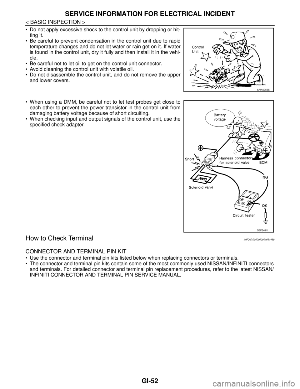
Do not apply excessive shock to the control unit by dropping or hit-
ting it.
Be careful to prevent condensation in the control unit due to rapid
temperature changes and do not let water or rain get on it. If water
is found in the control unit, dry it fully and then install it in the vehi-
cle.
Be careful not to let oil to get on the control unit connector.
Avoid cleaning the control unit with volatile oil.
Do not disassemble the control unit, and do not remove the upper
and lower covers.
When using a DMM, be careful not to let test probes get close to
each other to prevent the power transistor in the control unit from
damaging battery voltage because of short circuiting.
When checking input and output signals of the control unit, use the
specified check adapter.
How to Check TerminalINFOID:0000000001691469
CONNECTOR AND TERMINAL PIN KIT
Use the connector and terminal pin kits listed below when replacing connectors or terminals.
The connector and terminal pin kits contain some of the most commonly used NISSAN/INFINITI connectors
and terminals. For detailed connector and terminal pin replacement procedures, refer to the latest NISSAN/
INFINITI CONNECTOR AND TERMINAL PIN SERVICE MANUAL.
SAIA0255E
SEF348N
Page 3255 of 5883
SERVICE INFORMATION FOR ELECTRICAL INCIDENT
GI-61
< BASIC INSPECTION >
C
D
E
F
G
H
I
J
K
L
MB
GI
N
O
P
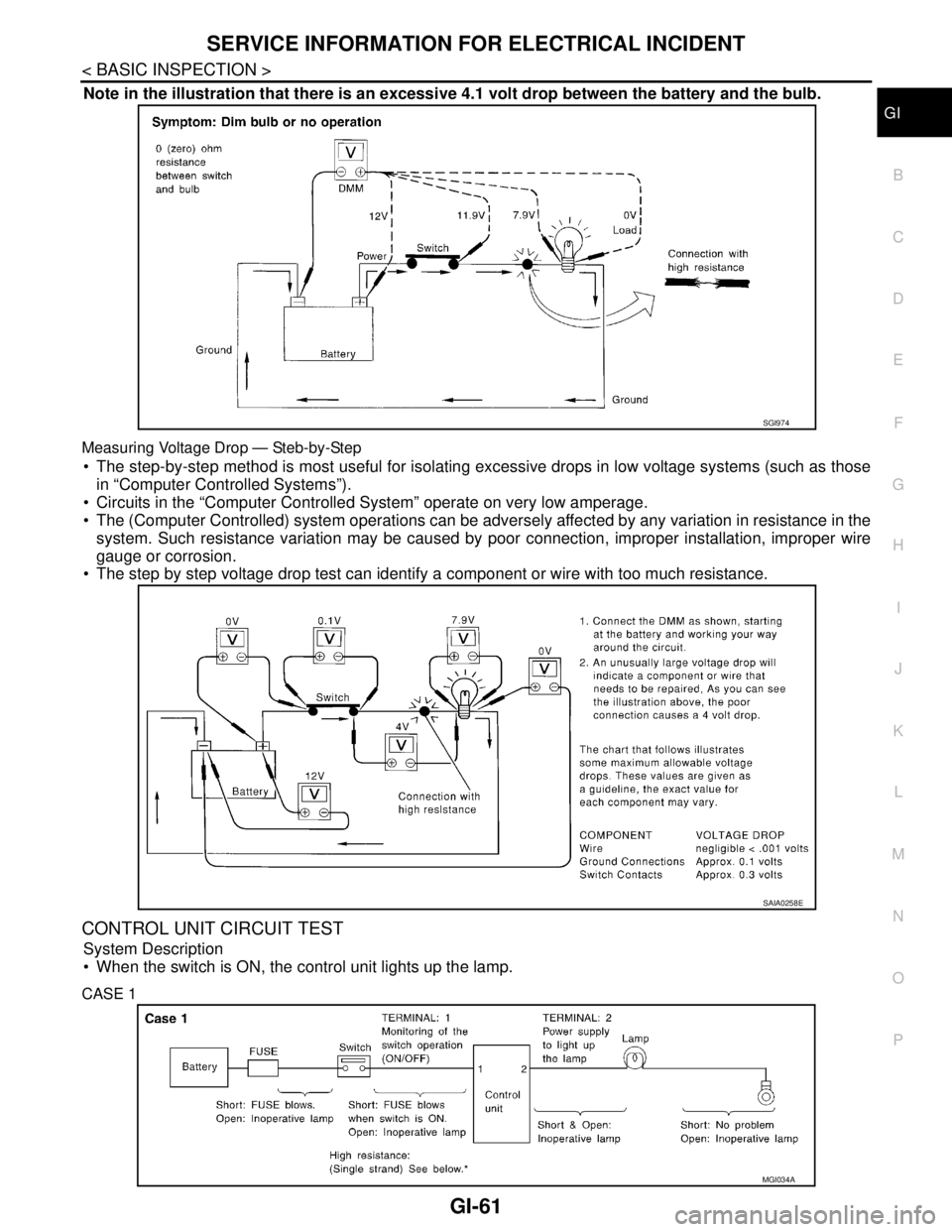
Note in the illustration that there is an excessive 4.1 volt drop between the battery and the bulb.
Measuring Voltage Drop — Steb-by-Step
The step-by-step method is most useful for isolating excessive drops in low voltage systems (such as those
in “Computer Controlled Systems”).
Circuits in the “Computer Controlled System” operate on very low amperage.
The (Computer Controlled) system operations can be adversely affected by any variation in resistance in the
system. Such resistance variation may be caused by poor connection, improper installation, improper wire
gauge or corrosion.
The step by step voltage drop test can identify a component or wire with too much resistance.
CONTROL UNIT CIRCUIT TEST
System Description
When the switch is ON, the control unit lights up the lamp.
CASE 1
SGI974
SAIA0258E
MGI034A
Page 3256 of 5883
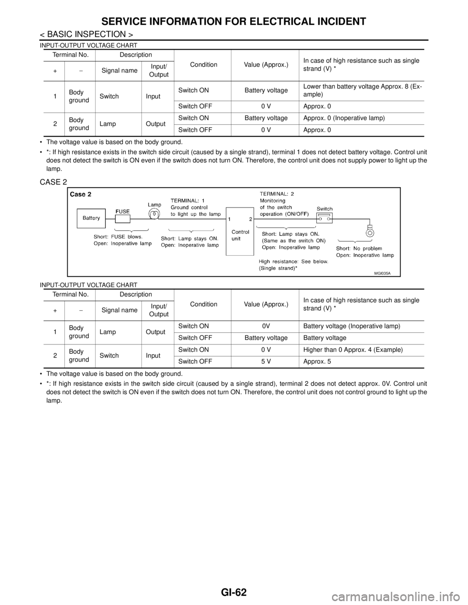
GI-62
< BASIC INSPECTION >
SERVICE INFORMATION FOR ELECTRICAL INCIDENT
INPUT-OUTPUT VOLTAGE CHART
The voltage value is based on the body ground.
*: If high resistance exists in the switch side circuit (caused by a single strand), terminal 1 does not detect battery voltage. Control unit
does not detect the switch is ON even if the switch does not turn ON. Therefore, the control unit does not supply power to light up the
lamp.
CASE 2
INPUT-OUTPUT VOLTAGE CHART
The voltage value is based on the body ground.
*: If high resistance exists in the switch side circuit (caused by a single strand), terminal 2 does not detect approx. 0V. Control unit
does not detect the switch is ON even if the switch does not turn ON. Therefore, the control unit does not control ground to light up the
lamp.Terminal No. Description
Condition Value (Approx.)In case of high resistance such as single
strand (V) *
+−Signal nameInput/
Output
1Body
groundSwitch InputSwitch ON Battery voltageLower than battery voltage Approx. 8 (Ex-
ample)
Switch OFF 0 V Approx. 0
2Body
groundLamp OutputSwitch ON Battery voltage Approx. 0 (Inoperative lamp)
Switch OFF 0 V Approx. 0
Terminal No. Description
Condition Value (Approx.)In case of high resistance such as single
strand (V) *
+−Signal nameInput/
Output
1Body
groundLamp OutputSwitch ON 0V Battery voltage (Inoperative lamp)
Switch OFF Battery voltage Battery voltage
2Body
groundSwitch InputSwitch ON 0 V Higher than 0 Approx. 4 (Example)
Switch OFF 5 V Approx. 5
MGI035A
Page 3308 of 5883
HA-26
< ON-VEHICLE MAINTENANCE >
ELECTRICAL LEAK DETECTOR
2. Connect a suitable A/C manifold gauge set to the A/C service ports.
3. Check if the A/C refrigerant pressure is at least 345 kPa (3.45 bar, 3.52 kg/cm
2, 50 psi) above 16°C. If less
than specification, recover/evacuate and recharge the system with the specified amount of refrigerant.
NOTE:
At temperatures below 16°C, leaks may not be detected since the system may not reach 345 kPa (3.45
bar, 3.52 kg/cm
2, 50 psi).
4. Perform the leak test from the high-pressure side (compressor discharge a to evaporator inlet f) to the
low-pressure side (evaporator drain hose g to shaft seal k). Refer to HA-27, "
Component". Perform a leak
check for the following areas carefully. Clean the component to be checked and move the leak detected
probe completely around the connection/component.
Compressor
Check the fitting of high- and low-pressure flexible hoses, relief valve and shaft seal.
Condenser
Check the fitting of high-pressure flexible hose and pipe, refrigerant pressure sensor.
Liquid tank
Check the refrigerant connection.
Service valves
Check all around the service valves. Ensure service valve caps are secured on the service valves (to
prevent leaks).
NOTE:
After removing A/C manifold gauge set from service valves, wipe any residue from valves to prevent any
false readings by leak detector.
Cooling unit (Evaporator)
With engine OFF, turn blower fan on “High” for at least 15 seconds to dissipate any refrigerant trace in
the cooling unit. Wait a minimum of 10 minutes accumulation time (refer to the manufacturer’s recom-
mended procedure for actual wait time) before inserting the leak detector probe into the drain hose.
Keep the probe inserted for at least 10 seconds. Use caution not to contaminate the probe tip with water
or dirt that may be in the drain hose.
5. If a leak detector detects a leak, verify at least once by blowing compressed air into area of suspected
leak, then repeat check as outlined above.
6. Do not stop when one leak is found. Continue to check for additional leaks at all system components.
If no leaks are found, perform steps 7-10.
7. Start engine.
8. Set the heater A/C control as follows;
a. A/C switch: ON
b. Mode control dial position: VENT (Ventilation)
c. Intake door lever position: Recirculation
d. Max. cold temperature
e. Fan speed: High
9. Run engine at 1,500 rpm for at least 2 minutes.
10. Turn engine off and perform leak check again following steps 4
through 6 above.
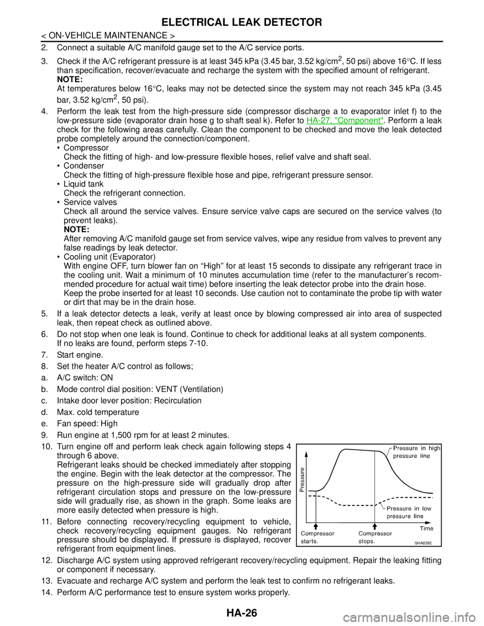
Refrigerant leaks should be checked immediately after stopping
the engine. Begin with the leak detector at the compressor. The
pressure on the high-pressure side will gradually drop after
refrigerant circulation stops and pressure on the low-pressure
side will gradually rise, as shown in the graph. Some leaks are
more easily detected when pressure is high.
11. Before connecting recovery/recycling equipment to vehicle,
check recovery/recycling equipment gauges. No refrigerant
pressure should be displayed. If pressure is displayed, recover
refrigerant from equipment lines.
12. Discharge A/C system using approved refrigerant recovery/recycling equipment. Repair the leaking fitting
or component if necessary.
13. Evacuate and recharge A/C system and perform the leak test to confirm no refrigerant leaks.
14. Perform A/C performance test to ensure system works properly.
SHA839E
Page 3366 of 5883
![NISSAN TIIDA 2007 Service Repair Manual PTC HEATER CONTROL SYSTEM
HAC-33
< COMPONENT DIAGNOSIS >[MANUAL AIR CONDITIONER]
C
D
E
F
G
H
J
K
L
MA
B
HAC
N
O
P
PTC HEATER CONTROL SYSTEM
PTC HEATER (300 WATT)
PTC HEATER (300 WATT) : PTC Heater Sys NISSAN TIIDA 2007 Service Repair Manual PTC HEATER CONTROL SYSTEM
HAC-33
< COMPONENT DIAGNOSIS >[MANUAL AIR CONDITIONER]
C
D
E
F
G
H
J
K
L
MA
B
HAC
N
O
P
PTC HEATER CONTROL SYSTEM
PTC HEATER (300 WATT)
PTC HEATER (300 WATT) : PTC Heater Sys](/manual-img/5/57395/w960_57395-3365.png)
PTC HEATER CONTROL SYSTEM
HAC-33
< COMPONENT DIAGNOSIS >[MANUAL AIR CONDITIONER]
C
D
E
F
G
H
J
K
L
MA
B
HAC
N
O
P
PTC HEATER CONTROL SYSTEM
PTC HEATER (300 WATT)
PTC HEATER (300 WATT) : PTC Heater System DescriptionINFOID:0000000001674171
SYSTEM DESCRIPTION
The PTC heater system is controlled by ambient temperature, water temperature, FAN ON signal and temper-
ature control dial. Hot air is supplied to a discharge air outlet by PTC heater that generates heat electrically
even when engine coolant temperature is low.
Component Parts
PTC heater system components are:
PTC control unit
PTC heater
PTC relay-1
Water temperature sensor
Full hot switch
Ambient sensor
System Operation
PTC heater system starts when all the following conditions are met:
Less than 35 minutes after ignition switch ON.
Blower control dial ON (Blower motor operates.) and temperature control dial full hot position (Full hot switch
ON).
Ambient temperature is lower than 0°C (32°F).
Engine coolant temperature is lower than 65°C (149°F) (condition
1), or when it becomes lower than 60°C (140°F) again (condition 2)
on startup.
Engine speed is more than 1100 rpm and after a lapse of more
than 10 seconds.
PTC heater system stops when any of the following conditions is
met:
More than 35 minutes later after ignition switch ON.
Blower control dial OFF (Blower motor OFF) and/or temperature
control dial except full hot position (Full hot switch OFF).
Ambient temperature is higher than 0°C (32°F).
Engine coolant temperature is higher than 65°C (149°F).
When engine speed becomes less than 800 rpm.
SJIA0968E
AWIIA0354GB
Page 3367 of 5883
![NISSAN TIIDA 2007 Service Repair Manual HAC-34
< COMPONENT DIAGNOSIS >[MANUAL AIR CONDITIONER]
PTC HEATER CONTROL SYSTEM
PTC HEATER (300 WATT) : PTC Heater Component Description
INFOID:0000000001674172
COMPONENT DESCRIPTION
PTC Control Unit NISSAN TIIDA 2007 Service Repair Manual HAC-34
< COMPONENT DIAGNOSIS >[MANUAL AIR CONDITIONER]
PTC HEATER CONTROL SYSTEM
PTC HEATER (300 WATT) : PTC Heater Component Description
INFOID:0000000001674172
COMPONENT DESCRIPTION
PTC Control Unit](/manual-img/5/57395/w960_57395-3366.png)
HAC-34
< COMPONENT DIAGNOSIS >[MANUAL AIR CONDITIONER]
PTC HEATER CONTROL SYSTEM
PTC HEATER (300 WATT) : PTC Heater Component Description
INFOID:0000000001674172
COMPONENT DESCRIPTION
PTC Control Unit
The PTC control unit is attached on the A/C unit assembly. It controls
PTC heater by ambient temperature, water temperature, FAN ON
signal and temperature control dial.
PTC Heater
The PTC heater is attached on the A/C unit assembly. It generates
heat electrically.
Ambient Sensor
The ambient sensor is attached on the radiator core support upper. It
detects ambient temperature and converts it into a resistance value
which is then input into the PTC control unit.
Water Temperature Sensor
The water temperature sensor is attached on heater pipe. It detects
water temperature and converts it into a resistance value which is
then input in to PTC control unit.
Full Hot Switch
SJIA0906E
SJIA0907E
AWIIA0600ZZ
SJIA0908E