Page 5426 of 5883
TM-480
< ON-VEHICLE MAINTENANCE >[TYPE 2 (4AT: RE4F03B)]
LINE PRESSURE TEST
LINE PRESSURE TEST
Inspection and JudgmentINFOID:0000000001726681
LINE PRESSURE TEST PORTS
Location of line pressure test ports are shown in the figure.
Always replace pressure plugs as they are self-sealing bolts.
LINE PRESSURE TEST PROCEDURE
1. Check ATF and engine oil levels. If necessary, add ATF or
engine oil.
2. Drive vehicle for approx. 10 minutes or until engine oil and ATF
reach operating temperature.
3. Install oil pressure gauge to corresponding line pressure test
port.
4. Set parking brake and block wheels.
SCIA7187E
ATF operating temperature: 50 - 80°C (122 -176°F)
SAT647B
SCIA6528J
SAT513G
Page 5514 of 5883
![NISSAN TIIDA 2007 Service Repair Manual TM-568
< DISASSEMBLY AND ASSEMBLY >[TYPE 2 (4AT: RE4F03B)]
REPAIR FOR COMPONENT PARTS
6. Apply compressed air into the oil hole on transaxle case as
shown to raise piston while strongly pressing the w](/manual-img/5/57395/w960_57395-5513.png "NISSAN TIIDA 2007 Service Repair Manual TM-568
< DISASSEMBLY AND ASSEMBLY >[TYPE 2 (4AT: RE4F03B)]
REPAIR FOR COMPONENT PARTS
6. Apply compressed air into the oil hole on transaxle case as
shown to raise piston while strongly pressing the w")
TM-568
< DISASSEMBLY AND ASSEMBLY >[TYPE 2 (4AT: RE4F03B)]
REPAIR FOR COMPONENT PARTS
6. Apply compressed air into the oil hole on transaxle case as
shown to raise piston while strongly pressing the whole low &
reverse brake piston by hand. When applying compressed air,
strongly press the whole piston and adjust the pressure so that it
is raised evenly. Portion (A) (low & reverse brake pressure)
especially tends to tilt.
CAUTION:
Apply air gradually and allow low & reverse brake piston to
come out evenly.
7. Remove low & reverse brake piston from transaxle case by turn-
ing it.
8. Inspect transaxle case. Replace if damaged or worn.
9. Remove seal ring (1) and D-ring (2) from low & reverse brake
piston (3).
INSPECTION
Low & Reverse Brake Snap Rings
Check for deformation, fatigue or damage. Replace if necessary.
Low & Reverse Brake Drive Plates
Check facing for burns, cracks or damage. Replace if necessary.
Measure thickness of facing.
CAUTION:
Measure the thickness at 3 locations and find the average.
Inspect ALL drive plates.
Replace if the thickness is below the allowable limit.
Low & Reverse Brake Dish Plates
Check for deformation or damage.
SCIA6346J
SCIA6516J
Thickness of drive plate
Standard and allowable limit:
Refer to TM-321, "
Clutches and Brakes".
SAT162D
Page 5696 of 5883
CONTROLLER
VTL-35
< ON-VEHICLE REPAIR >[MANUAL AIR CONDITIONER]
C
D
E
F
G
H
J
K
L
MA
B
VTL
N
O
P
Disassembly and AssemblyINFOID:0000000001696529
CAUTION:
Install inner cable of each door cable to the corresponding
lever, as shown in the figure. Press outer cable until it hooks on
the tabs and becomes secure.
1. Air mix door cable 2. Intake door cable 3. Mode door cable
4. A/C controller assembly 5. Mode control dial 6. Rear DEF button
7. A/C button 8. Temperature control dial 9. Illumination bulb
10. Intake door lever knob 11. Fan control dial
ZJIA0106J
MJIA0038E
Page 5770 of 5883
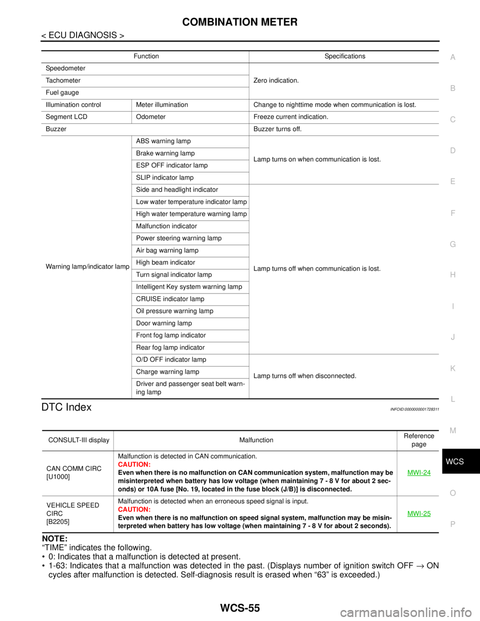
WCS
COMBINATION METER
WCS-55
< ECU DIAGNOSIS >
C
D
E
F
G
H
I
J
K
L
MB A
O
P
DTC IndexINFOID:0000000001728311
NOTE:
“TIME” indicates the following.
0: Indicates that a malfunction is detected at present.
1-63: Indicates that a malfunction was detected in the past. (Displays number of ignition switch OFF → ON
cycles after malfunction is detected. Self-diagnosis result is erased when “63” is exceeded.)
Function Specifications
Speedometer
Zero indication. Tachometer
Fuel gauge
Illumination control Meter illumination Change to nighttime mode when communication is lost.
Segment LCD Odometer Freeze current indication.
Buzzer Buzzer turns off.
Warning lamp/indicator lampABS warning lamp
Lamp turns on when communication is lost. Brake warning lamp
ESP OFF indicator lamp
SLIP indicator lamp
Side and headlight indicator
Lamp turns off when communication is lost. Low water temperature indicator lamp
High water temperature warning lamp
Malfunction indicator
Power steering warning lamp
Air bag warning lamp
High beam indicator
Turn signal indicator lamp
Intelligent Key system warning lamp
CRUISE indicator lamp
Oil pressure warning lamp
Door warning lamp
Front fog lamp indicator
Rear fog lamp indicator
O/D OFF indicator lamp
Lamp turns off when disconnected. Charge warning lamp
Driver and passenger seat belt warn-
ing lamp
CONSULT-III display MalfunctionReference
page
CAN COMM CIRC
[U1000]Malfunction is detected in CAN communication.
CAUTION:
Even when there is no malfunction on CAN communication system, malfunction may be
misinterpreted when battery has low voltage (when maintaining 7 - 8 V for about 2 sec-
onds) or 10A fuse [No. 19, located in the fuse block (J/B)] is disconnected.MWI-24
VEHICLE SPEED
CIRC
[B2205]Malfunction is detected when an erroneous speed signal is input.
CAUTION:
Even when there is no malfunction on speed signal system, malfunction may be misin-
terpreted when battery has low voltage (when maintaining 7 - 8 V for about 2 seconds). MWI-25
![NISSAN TIIDA 2007 Service Repair Manual TM-480
< ON-VEHICLE MAINTENANCE >[TYPE 2 (4AT: RE4F03B)]
LINE PRESSURE TEST
LINE PRESSURE TEST
Inspection and JudgmentINFOID:0000000001726681
LINE PRESSURE TEST PORTS
Location of line pressure test po](/manual-img/5/57395/w960_57395-5425.png "NISSAN TIIDA 2007 Service Repair Manual TM-480
< ON-VEHICLE MAINTENANCE >[TYPE 2 (4AT: RE4F03B)]
LINE PRESSURE TEST
LINE PRESSURE TEST
Inspection and JudgmentINFOID:0000000001726681
LINE PRESSURE TEST PORTS
Location of line pressure test po")
![NISSAN TIIDA 2007 Service Repair Manual CONTROLLER
VTL-35
< ON-VEHICLE REPAIR >[MANUAL AIR CONDITIONER]
C
D
E
F
G
H
J
K
L
MA
B
VTL
N
O
P
Disassembly and AssemblyINFOID:0000000001696529
CAUTION:
Install inner cable of each door cable to the](/manual-img/5/57395/w960_57395-5695.png "NISSAN TIIDA 2007 Service Repair Manual CONTROLLER
VTL-35
< ON-VEHICLE REPAIR >[MANUAL AIR CONDITIONER]
C
D
E
F
G
H
J
K
L
MA
B
VTL
N
O
P
Disassembly and AssemblyINFOID:0000000001696529
CAUTION:
Install inner cable of each door cable to the")