2007 NISSAN TIIDA height adjustment
[x] Cancel search: height adjustmentPage 1332 of 5883
![NISSAN TIIDA 2007 Service Repair Manual DOOR
DLK-743
< REMOVAL AND INSTALLATION >[WITHOUT I-KEY, WITH SUPER LOCK]
C
D
E
F
G
H
I
J
L
MA
B
DLK
N
O
P
DOOR
Fitting AdjustmentINFOID:0000000001732059
FRONT DOOR
Longitudinal Clearance and Surface NISSAN TIIDA 2007 Service Repair Manual DOOR
DLK-743
< REMOVAL AND INSTALLATION >[WITHOUT I-KEY, WITH SUPER LOCK]
C
D
E
F
G
H
I
J
L
MA
B
DLK
N
O
P
DOOR
Fitting AdjustmentINFOID:0000000001732059
FRONT DOOR
Longitudinal Clearance and Surface](/manual-img/5/57395/w960_57395-1331.png)
DOOR
DLK-743
< REMOVAL AND INSTALLATION >[WITHOUT I-KEY, WITH SUPER LOCK]
C
D
E
F
G
H
I
J
L
MA
B
DLK
N
O
P
DOOR
Fitting AdjustmentINFOID:0000000001732059
FRONT DOOR
Longitudinal Clearance and Surface Height Adjustment at Front End
Access from inside the fender to loosen the hinge bolts. Raise the front door at rear end to adjust.
Surface Height Adjustment
Loosen the front door bolts, and adjust the surface height difference of fender and front door according to the
fitting standard dimension.
Striker Adjustment
1. Front fender 2. Front door outer 3. Rear door outer
4. Rear fender 5. Front door weatherstrip 6. Front door sash
7. Rear door weatherstrip 8. Rear door sash
PIIB6516E
Page 1333 of 5883
![NISSAN TIIDA 2007 Service Repair Manual DLK-744
< REMOVAL AND INSTALLATION >[WITHOUT I-KEY, WITH SUPER LOCK]
DOOR
1.
REAR DOOR
Longitudinal Clearance and Surface Height Adjustment at Front End
1. Remove the center pillar upper and lower gar NISSAN TIIDA 2007 Service Repair Manual DLK-744
< REMOVAL AND INSTALLATION >[WITHOUT I-KEY, WITH SUPER LOCK]
DOOR
1.
REAR DOOR
Longitudinal Clearance and Surface Height Adjustment at Front End
1. Remove the center pillar upper and lower gar](/manual-img/5/57395/w960_57395-1332.png)
DLK-744
< REMOVAL AND INSTALLATION >[WITHOUT I-KEY, WITH SUPER LOCK]
DOOR
1.
REAR DOOR
Longitudinal Clearance and Surface Height Adjustment at Front End
1. Remove the center pillar upper and lower garnishes. Refer to INT-20, "Removal and Installation".
2. Access from inside the vehicle to loosen the hinge nuts. Open the rear door, and raise the rear door at
rear end to adjust.
Surface Height Adjustment
Loosen the front door striker bolts and rear door hinge nuts, and adjust the surface height difference of front
and rear doors according to the fitting standard dimension.
Striker Adjustment
1.
BACK DOOR
Longitudinal Clearance and Surface Height Adjustment
16.7 N·m (1.7 kg-m, 12 ft-lb)
PIIB2804J
16.7 N·m (1.7 kg-m, 12 ft-lb)
PIIB2804J
Page 1347 of 5883
![NISSAN TIIDA 2007 Service Repair Manual DLK-758
< REMOVAL AND INSTALLATION >[WITHOUT I-KEY, WITH SUPER LOCK]
TRUNK LID
TRUNK LID
Fitting AdjustmentINFOID:0000000001732067
Longitudinal and lateral clearance adjustment
1. With the striker rel NISSAN TIIDA 2007 Service Repair Manual DLK-758
< REMOVAL AND INSTALLATION >[WITHOUT I-KEY, WITH SUPER LOCK]
TRUNK LID
TRUNK LID
Fitting AdjustmentINFOID:0000000001732067
Longitudinal and lateral clearance adjustment
1. With the striker rel](/manual-img/5/57395/w960_57395-1346.png)
DLK-758
< REMOVAL AND INSTALLATION >[WITHOUT I-KEY, WITH SUPER LOCK]
TRUNK LID
TRUNK LID
Fitting AdjustmentINFOID:0000000001732067
Longitudinal and lateral clearance adjustment
1. With the striker released, loosen the trunk lid hinge nuts and close the trunk lid.
2. Make the lateral clearance and the clearance to the rear window glass equal. Then open the trunk lid to
tighten the nuts.
Surface height adjustment
1. Loosen the striker bolts. Raise the striker to the top position, and temporarily tighten the upper bolt.
2. Close the trunk lid lightly and adjust the surface height. Then open the trunk lid and tighten the striker
bolts.
Trunk Lid AssemblyINFOID:0000000001732068
REMOVAL
1. Remove the trunk lid finisher. Refer to XX-XX, "*****" .
2. Remove the trunk lid wire harness.
1. Rear fender 2. Trunk lid 3. Rear combination lamp
4. Rear bumper fascia a. 4.0 ± 1.0 mm (0.16 ± 0.04 in) b. 3.5 ± 1.0 mm (0.14 ± 0.04 in)
c. 4.5 ± 1.7 mm (0.03 ± 0.06 in) d. 7.0 ± 2.2 mm (0.28 ± 0.09 in)
LIIA2932E
Page 2770 of 5883
![NISSAN TIIDA 2007 Service Repair Manual SERVICE DATA AND SPECIFICATIONS (SDS)
EM-123
< SERVICE DATA AND SPECIFICATIONS (SDS) [HR16DE]
C
D
E
F
G
H
I
J
K
L
MA
EM
N
P O
*: When engine is cold.
Spark PlugINFOID:0000000001381441
SPARK PLUG (PLAT NISSAN TIIDA 2007 Service Repair Manual SERVICE DATA AND SPECIFICATIONS (SDS)
EM-123
< SERVICE DATA AND SPECIFICATIONS (SDS) [HR16DE]
C
D
E
F
G
H
I
J
K
L
MA
EM
N
P O
*: When engine is cold.
Spark PlugINFOID:0000000001381441
SPARK PLUG (PLAT](/manual-img/5/57395/w960_57395-2769.png)
SERVICE DATA AND SPECIFICATIONS (SDS)
EM-123
< SERVICE DATA AND SPECIFICATIONS (SDS) [HR16DE]
C
D
E
F
G
H
I
J
K
L
MA
EM
N
P O
*: When engine is cold.
Spark PlugINFOID:0000000001381441
SPARK PLUG (PLATINUM-TIPPED TYPE)
Unit: mm (in)
Exhaust ManifoldINFOID:0000000001381442
EXHAUST MANIFOLD
Unit: mm (in)
CamshaftINFOID:0000000001381443
CAMSHAFT
Unit: mm (in)
Location Tension adjustment * Unit: N (kg, lb) Frequency adjustment * Unit: Hz
Used belt
New beltUsed belt
New belt
Limit After adjusted Limit After adjusted
Drive beltWith A/C models 500 (51.0, 112)876 - 964
(89.4 - 98.3,
197 - 217)1064 - 1152
(108.5 - 117.5,
239 - 259)163 216 - 225 238 - 246
Without A/C models 500 (51.0, 112)876 - 964
(89.4 - 98.3,
197 - 217)1064 - 1152
(108.5 - 117.5,
239 - 259)183 242 - 252 266 - 276
MakeNGK
Standard typePLZKAR6A-11
Gap (Nominal)1.1 (0.043)
Items Limit
Surface distortion Exhaust manifold 0.3 (0.012)
Items Standard Limit
Camshaft runout [TIR*] 0.02 (0.0008) 0.1 (0.004)
Camshaft cam height “A”Intake 41.705 - 41.895 (1.6419 - 1.6494) —
Exhaust 40.175 - 40.365 (1.5817 - 1.5892) —
Camshaft journal diameterNo. 1 27.935 - 27.955 (1.0998 - 1.1006) —
No. 2, 3, 4, 5 24.950 - 24.970 (0.9823 - 0.9831) —
Camshaft bracket inner diameterNo. 1 28.000 - 28.021 (1.1024 - 1.1032) —
No. 2, 3, 4, 5 25.000 - 25.021 (0.9843 - 0.9851) —
Camshaft journal oil clearanceNo. 1 0.045 - 0.086 (0.0018 - 0.0034)
0.15 (0.0059)
No. 2, 3, 4, 5 0.030 - 0.071 (0.0012 - 0.0028)
SEM671
Page 3004 of 5883

EXL-3
C
D
E
F
G
H
I
J
K
MA
B
EXL
N
O
P
TURN SIGNAL AND HAZARD WARNING
LAMPS ...............................................................
66
Wiring Diagram .......................................................66
PARKING, LICENSE PLATE AND TAIL
LAMPS ...............................................................
67
WITH DAYTIME LIGHT SYSTEM .............................67
WITH DAYTIME LIGHT SYSTEM : Wiring Dia-
gram ........................................................................
67
WITHOUT DAYTIME LIGHT SYSTEM ......................67
WITHOUT DAYTIME LIGHT SYSTEM : Wiring Di-
agram ......................................................................
68
STOP LAMP .......................................................69
Wiring Diagram .......................................................69
BACK-UP LAMP ................................................70
Wiring Diagram .......................................................70
ECU DIAGNOSIS .........................................71
BCM (BODY CONTROL MODULE) ...................71
Description ..............................................................71
IPDM E/R (INTELLIGENT POWER DISTRI-
BUTION MODULE ENGINE ROOM) .................
72
Description ..............................................................72
SYMPTOM DIAGNOSIS ..............................73
EXTERIOR LIGHTING SYSTEM SYMPTOMS ....73
Symptom Table .......................................................73
NORMAL OPERATING CONDITION .................75
Description ..............................................................75
BOTH SIDE HEADLAMPS DO NOT SWITCH
TO HIGH BEAM .................................................
76
Description ..............................................................76
Diagnosis Procedure ...............................................76
BOTH SIDE HEADLAMPS (LO) ARE NOT
TURNED ON .......................................................
77
Description ..............................................................77
Diagnosis Procedure ...............................................77
PARKING, LICENSE PLATE AND TAIL
LAMPS ARE NOT TURNED ON ........................
78
Description ..............................................................78
Diagnosis Procedure ...............................................78
BOTH SIDE FRONT FOG LAMPS ARE NOT
TURNED ON .......................................................
79
Description ..............................................................79
Diagnosis Procedure ...............................................79
PRECAUTION ..............................................80
PRECAUTIONS ..................................................80
Precaution for Supplemental Restraint System
(SRS) "AIR BAG" and "SEAT BELT PRE-TEN-
SIONER" .................................................................
80
ON-VEHICLE MAINTENANCE ....................81
HEADLAMP ......................................................81
Aiming Adjustment ...................................................81
FRONT FOG LAMP ..........................................83
Aiming Adjustment ...................................................83
ON-VEHICLE REPAIR .................................84
HEADLAMP ......................................................84
Bulb Replacement ...................................................84
Removal and Installation .........................................84
Disassembly and Assembly - Halogen ....................85
Disassembly and Assembly - Xenon .......................86
FRONT FOG LAMP ..........................................87
Bulb Replacement ...................................................87
Removal and Installation .........................................87
HEADLAMP AIMING CONTROL ......................88
Removal and Installation of Headlamp Aiming
Switch ......................................................................
88
Removal and Installation of Height Sensor .............89
AUTO LIGHT SYSTEM .....................................91
Removal and Installation of Light and Rain Sensor
....
91
SIDE TURN SIGNAL LAMP ..............................92
Bulb Replacement ...................................................92
Removal and Installation .........................................92
REAR COMBINATION LAMP ...........................93
Bulb Replacement ...................................................93
Removal and Installation .........................................93
Disassembly and Assembly .....................................93
HIGH-MOUNTED STOP LAMP ........................96
Bulb Replacement ...................................................96
Removal and Installation .........................................96
LICENSE PLATE LAMP ...................................98
Bulb Replacement ...................................................98
Removal and Installation .........................................98
REAR FOG LAMP ...........................................100
Bulb Replacement .................................................100
Removal and Installation .......................................100
LIGHTING & TURN SIGNAL SWITCH ...........101
Removal and Installation .......................................101
HAZARD SWITCH ..........................................102
Removal and Installation .......................................102
SERVICE DATA AND SPECIFICATIONS
(SDS) ..........................................................
103
Page 3182 of 5883

FSU-6
< ON-VEHICLE MAINTENANCE >
FRONT SUSPENSION ASSEMBLY
ON-VEHICLE MAINTENANCE
FRONT SUSPENSION ASSEMBLY
On-Vehicle Inspection and ServiceINFOID:0000000001716890
Make sure the mounting conditions (looseness, back lash) of each component and component conditions
(wear, damage) are normal.
INSPECTION OF LOWER BALL JOINT END PLAY
1. Set front wheels in a straight-ahead position. Do not depress brake pedal.
2. Place an iron bar or similar tool between transverse link and steering knuckle.
3. Measure axial end play by prying it up and down.
CAUTION:
Be careful not to damage ball joint boot. Do not damage the installation position by applying
excessive force.
STRUT INSPECTION
Check for oil leakage, damage and replace as necessary.
Wheel Alignment InspectionINFOID:0000000001716891
PRELIMINARY INSPECTION
WARNING:
Always adjust the alignment with the vehicle on a flat surface.
NOTE:
If alignment is out of specification, inspect and replace any damaged or worn rear suspension parts before
making any adjustments.
1. Check and adjust the wheel alignment with the vehicle under unladen conditions. “Unladen conditions”
means that the fuel, coolant, and lubricant are full; and that the spare tire, jack, hand tools and mats are in
their designated positions.
2. Check the tires for incorrect air pressure and excessive wear.
3. Check the wheels for run out and damage. Refer to WT-5, "
Inspection" .
4. Check the wheel bearing axial end play. Refer to FA X - 5 , "
On-Vehicle Inspection and Service" .
5. Check the shock absorbers for leaks or damage.
6. Check each mounting point of the suspension components for any excessive looseness or damage.
7. Check each link, arm, and the suspension member for any damage.
8. Check the vehicle height. Refer to FSU-18, "
Wheelarch Height (Unladen*)" .
GENERAL INFORMATION AND RECOMMENDATIONS
1. A Four-Wheel Thrust Alignment should be performed.
This type of alignment is recommended for any NISSAN vehicle.
The four-wheel “thrust” process helps ensure that the vehicle is properly aligned and the steering wheel
is centered.
The alignment machine itself should be capable of accepting any NISSAN vehicle.
The alignment machine should be checked to ensure that it is level.
2. Make sure the alignment machine is properly calibrated.
Your alignment machine should be regularly calibrated in order to give correct information.
Check with the manufacturer of your specific alignment machine for their recommended Service/Cali-
bration Schedule.
THE ALIGNMENT PROCESS
IMPORTANT: Use only the alignment specifications listed in this Service Manual. Refer to FSU-17, "Wheel
Alignment (Unladen*)" .
1. When displaying the alignment settings, many alignment machines use “indicators”: (Green/red, plus or
minus, Go/No Go). Do NOT use these indicators. Axial end play : 0 mm (0 in)
Page 4566 of 5883

RF-32
< ON-VEHICLE REPAIR >
SUNROOF SYSTEM
1. Remove headlining. Refer to INT-29, "Component".
2. Visually check drain hoses for:
Proper connection at sunroof unit assembly.
Damage, pinch, cracks, deterioration.
Proper fastening and routing on body panels.
3. Pour water through drain hoses to determine watertight performance.
If a damaged or leaking portion in any drain hose is found, replace entire drain hose as an assembly.
Fitting AdjustmentINFOID:0000000001724430
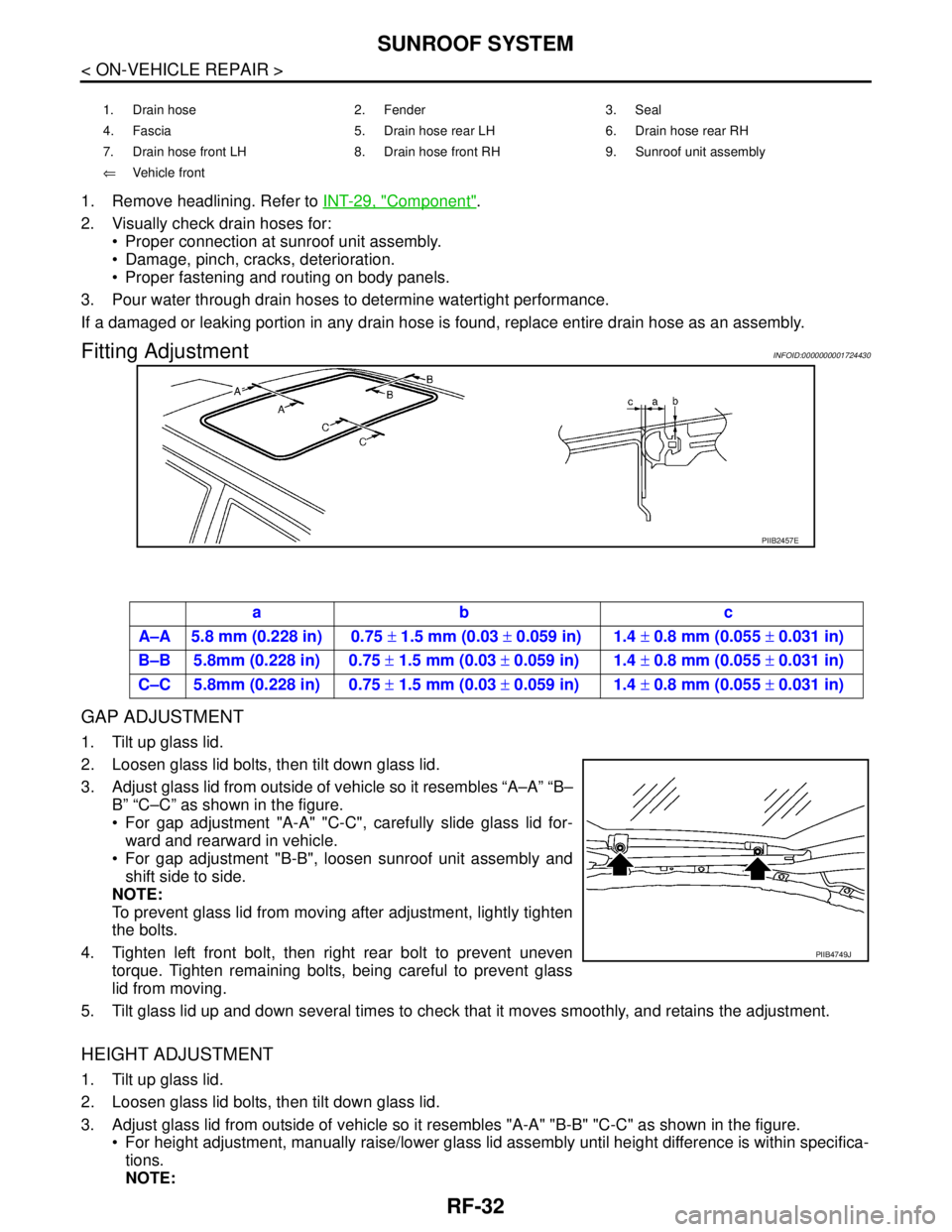
GAP ADJUSTMENT
1. Tilt up glass lid.
2. Loosen glass lid bolts, then tilt down glass lid.
3. Adjust glass lid from outside of vehicle so it resembles “A–A” “B–
B” “C–C” as shown in the figure.
For gap adjustment "A-A" "C-C", carefully slide glass lid for-
ward and rearward in vehicle.
For gap adjustment "B-B", loosen sunroof unit assembly and
shift side to side.
NOTE:
To prevent glass lid from moving after adjustment, lightly tighten
the bolts.
4. Tighten left front bolt, then right rear bolt to prevent uneven
torque. Tighten remaining bolts, being careful to prevent glass
lid from moving.
5. Tilt glass lid up and down several times to check that it moves smoothly, and retains the adjustment.
HEIGHT ADJUSTMENT
1. Tilt up glass lid.
2. Loosen glass lid bolts, then tilt down glass lid.
3. Adjust glass lid from outside of vehicle so it resembles "A-A" "B-B" "C-C" as shown in the figure.
For height adjustment, manually raise/lower glass lid assembly until height difference is within specifica-
tions.
NOTE:
1. Drain hose 2. Fender 3. Seal
4. Fascia 5. Drain hose rear LH 6. Drain hose rear RH
7. Drain hose front LH 8. Drain hose front RH 9. Sunroof unit assembly
⇐Vehicle front
PIIB2457E
ab c
A–A 5.8 mm (0.228 in) 0.75 ± 1.5 mm (0.03 ± 0.059 in) 1.4 ± 0.8 mm (0.055 ± 0.031 in)
B–B 5.8mm (0.228 in) 0.75 ± 1.5 mm (0.03 ± 0.059 in) 1.4 ± 0.8 mm (0.055 ± 0.031 in)
C–C 5.8mm (0.228 in) 0.75 ± 1.5 mm (0.03 ± 0.059 in) 1.4 ± 0.8 mm (0.055 ± 0.031 in)
PIIB4749J
Page 4567 of 5883

SUNROOF SYSTEM
RF-33
< ON-VEHICLE REPAIR >
C
D
E
F
G
H
I
J
L
MA
B
RF
N
O
P
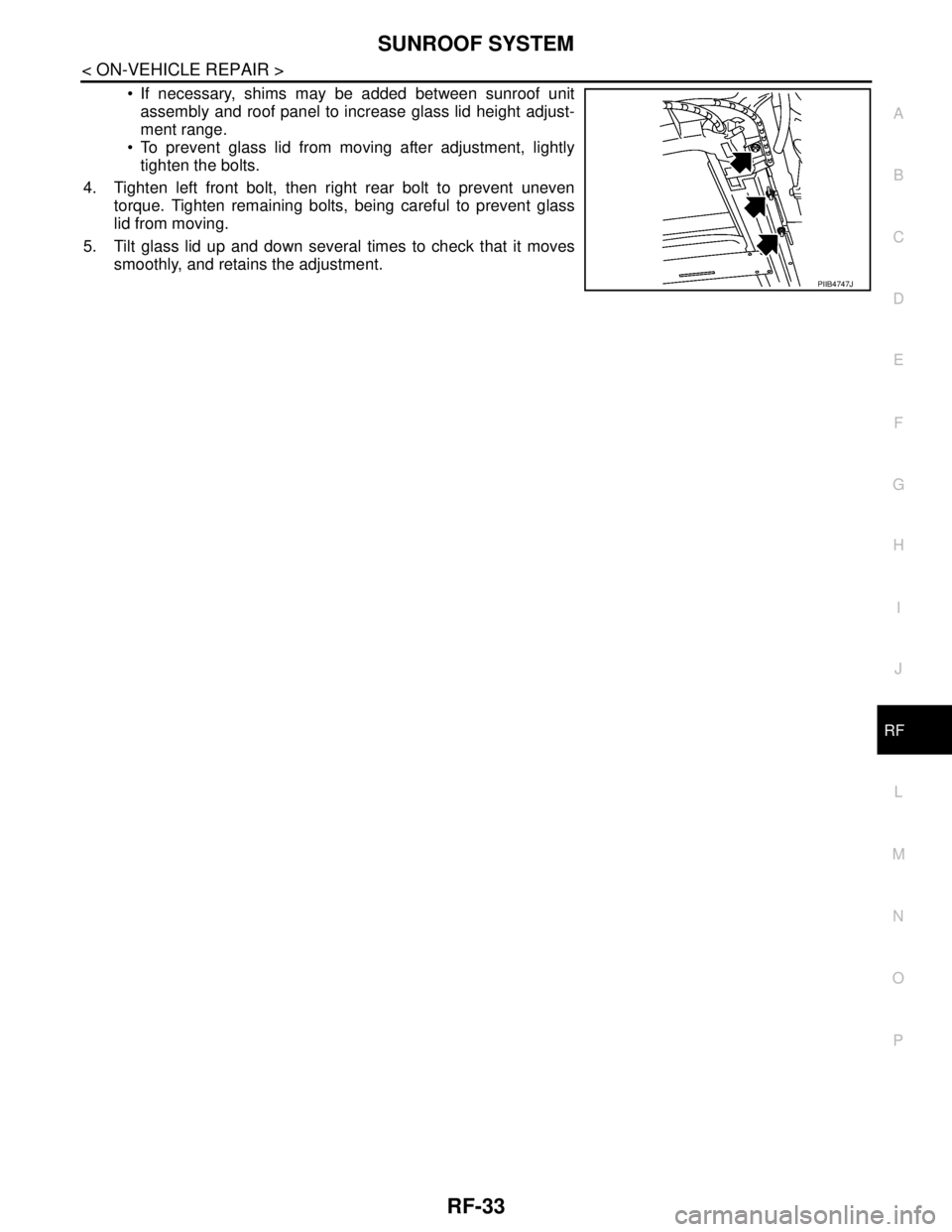
If necessary, shims may be added between sunroof unit
assembly and roof panel to increase glass lid height adjust-
ment range.
To prevent glass lid from moving after adjustment, lightly
tighten the bolts.
4. Tighten left front bolt, then right rear bolt to prevent uneven
torque. Tighten remaining bolts, being careful to prevent glass
lid from moving.
5. Tilt glass lid up and down several times to check that it moves
smoothly, and retains the adjustment.
PIIB4747J