2007 NISSAN TIIDA change key battery
[x] Cancel search: change key batteryPage 1216 of 5883
![NISSAN TIIDA 2007 Service Repair Manual DIAGNOSIS SYSTEM (BCM)
DLK-627
< FUNCTION DIAGNOSIS >[WITHOUT I-KEY, WITH SUPER LOCK]
C
D
E
F
G
H
I
J
L
MA
B
DLK
N
O
P
DIAGNOSIS SYSTEM (BCM)
COMMON ITEM
COMMON ITEM : CONSULT-III Function (BCM - COMM NISSAN TIIDA 2007 Service Repair Manual DIAGNOSIS SYSTEM (BCM)
DLK-627
< FUNCTION DIAGNOSIS >[WITHOUT I-KEY, WITH SUPER LOCK]
C
D
E
F
G
H
I
J
L
MA
B
DLK
N
O
P
DIAGNOSIS SYSTEM (BCM)
COMMON ITEM
COMMON ITEM : CONSULT-III Function (BCM - COMM](/manual-img/5/57395/w960_57395-1215.png)
DIAGNOSIS SYSTEM (BCM)
DLK-627
< FUNCTION DIAGNOSIS >[WITHOUT I-KEY, WITH SUPER LOCK]
C
D
E
F
G
H
I
J
L
MA
B
DLK
N
O
P
DIAGNOSIS SYSTEM (BCM)
COMMON ITEM
COMMON ITEM : CONSULT-III Function (BCM - COMMON ITEM)INFOID:0000000001397225
APPLICATION ITEM
CONSULT-III performs the following functions via CAN communication with BCM.
SYSTEM APPLICATION
BCM can perform the following functions for each system.
NOTE:
It can perform the diagnosis modes except the following for all sub system selection items.
DOOR LOCK
DOOR LOCK : CONSULT-III Function (BCM - DOOR LOCK)INFOID:0000000001397226
BCM CONSULT-III FUNCTION
CONSULT-III performs the following functions via CAN communication with BCM.
Diagnosis mode Function Description
WORK SUPPORT Changes the setting for each system function.
SELF-DIAG RESULTS Displays the diagnosis results judged by BCM. Refer to XX-XX, "*****"
.
CAN DIAG SUPPORT MNTR Monitors the reception status of CAN communication viewed from BCM.
DATA MONITOR The BCM input/output signals are displayed.
ACTIVE TEST The signals used to activate each device are forcibly supplied from BCM.
ECU IDENTIFICATION The BCM part number is displayed.
CONFIGURATION Enables to read and save the vehicle specification.
Enables to write the vehicle specification when replacing BCM.
System Sub system selection itemDiagnosis mode
WORK SUPPORT DATA MONITOR ACTIVE TEST
—BCM×
Door lock DOOR LOCK×××
Rear window defogger REAR DEFOGGER××
Warning chime BUZZER××
Interior room lamp timer INT LAMP×××
Remote keyless entry system MULTI REMOTE ENT×××
Exterior lamp HEAD LAMP×××
Wiper and washer WIPER×××
Turn signal and hazard warning lamps FLASHER××
Air conditioner AIR CONDITONER×
Intelligent Key system INTELLIGENT KEY×
Combination switch COMB SW×
Immobilizer IMMU××
Interior room lamp battery saver BATTERY SAVER×××
Trunk open TRUNK×
Vehicle security system THEFT ALM×××
Signal buffer system SIGNAL BUFFER××
PTC heater system PTC HEATER××
Page 3253 of 5883

SERVICE INFORMATION FOR ELECTRICAL INCIDENT
GI-59
< BASIC INSPECTION >
C
D
E
F
G
H
I
J
K
L
MB
GI
N
O
P
no voltage; open is between fuse block and SW1 (point A).
Close SW1 and probe at relay.
voltage; open is further down the circuit than the relay.
no voltage; open is between SW1 and relay (point B).
Close the relay and probe at the solenoid.
voltage; open is further down the circuit than the solenoid.
no voltage; open is between relay and solenoid (point C).
Any powered circuit can be diagnosed using the approach in the previous example.
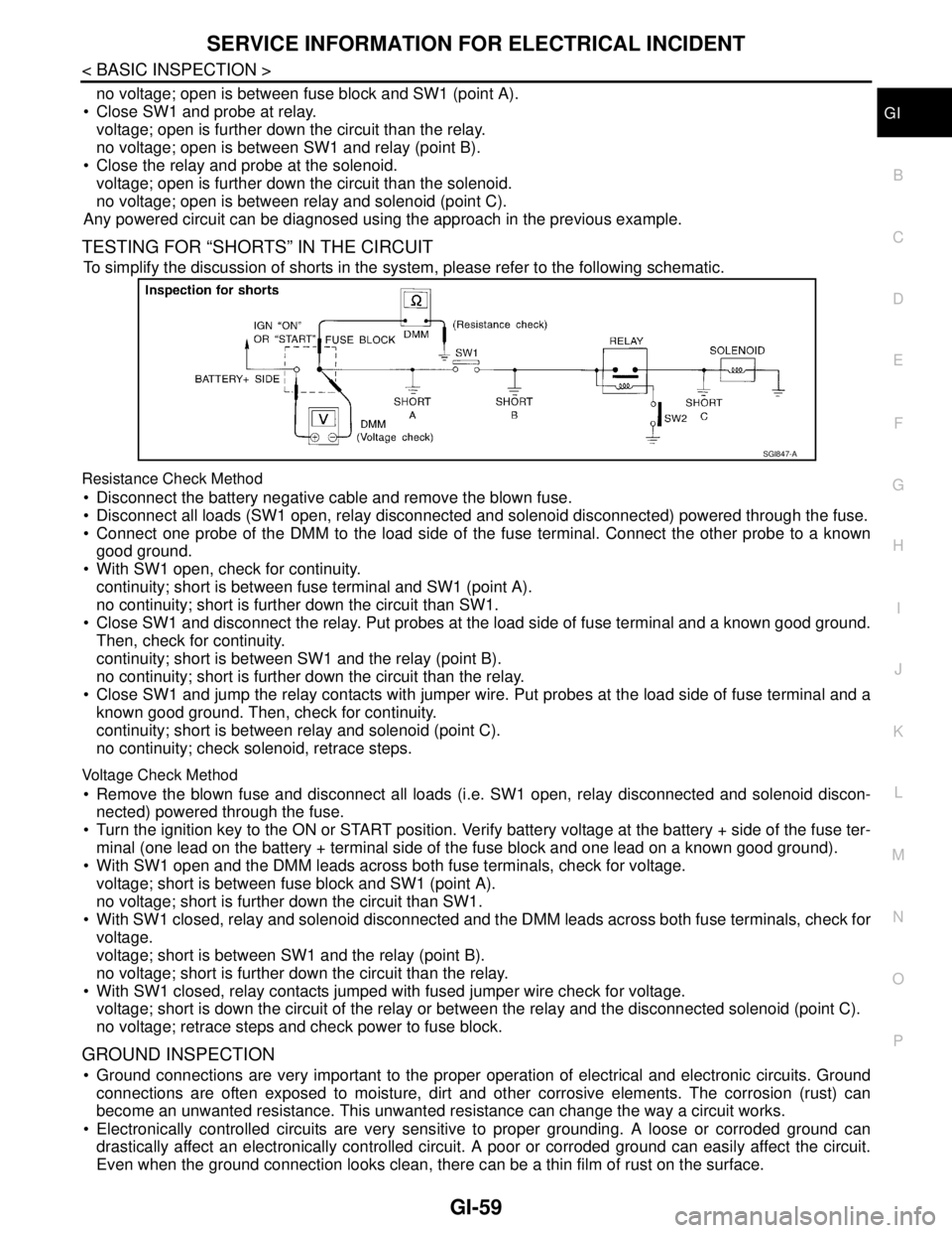
TESTING FOR “SHORTS” IN THE CIRCUIT
To simplify the discussion of shorts in the system, please refer to the following schematic.
Resistance Check Method
Disconnect the battery negative cable and remove the blown fuse.
Disconnect all loads (SW1 open, relay disconnected and solenoid disconnected) powered through the fuse.
Connect one probe of the DMM to the load side of the fuse terminal. Connect the other probe to a known
good ground.
With SW1 open, check for continuity.
continuity; short is between fuse terminal and SW1 (point A).
no continuity; short is further down the circuit than SW1.
Close SW1 and disconnect the relay. Put probes at the load side of fuse terminal and a known good ground.
Then, check for continuity.
continuity; short is between SW1 and the relay (point B).
no continuity; short is further down the circuit than the relay.
Close SW1 and jump the relay contacts with jumper wire. Put probes at the load side of fuse terminal and a
known good ground. Then, check for continuity.
continuity; short is between relay and solenoid (point C).
no continuity; check solenoid, retrace steps.
Voltage Check Method
Remove the blown fuse and disconnect all loads (i.e. SW1 open, relay disconnected and solenoid discon-
nected) powered through the fuse.
Turn the ignition key to the ON or START position. Verify battery voltage at the battery + side of the fuse ter-
minal (one lead on the battery + terminal side of the fuse block and one lead on a known good ground).
With SW1 open and the DMM leads across both fuse terminals, check for voltage.
voltage; short is between fuse block and SW1 (point A).
no voltage; short is further down the circuit than SW1.
With SW1 closed, relay and solenoid disconnected and the DMM leads across both fuse terminals, check for
voltage.
voltage; short is between SW1 and the relay (point B).
no voltage; short is further down the circuit than the relay.
With SW1 closed, relay contacts jumped with fused jumper wire check for voltage.
voltage; short is down the circuit of the relay or between the relay and the disconnected solenoid (point C).
no voltage; retrace steps and check power to fuse block.
GROUND INSPECTION
Ground connections are very important to the proper operation of electrical and electronic circuits. Ground
connections are often exposed to moisture, dirt and other corrosive elements. The corrosion (rust) can
become an unwanted resistance. This unwanted resistance can change the way a circuit works.
Electronically controlled circuits are very sensitive to proper grounding. A loose or corroded ground can
drastically affect an electronically controlled circuit. A poor or corroded ground can easily affect the circuit.
Even when the ground connection looks clean, there can be a thin film of rust on the surface.
SGI847-A
Page 3656 of 5883

INTERIOR ROOM LAMP CONTROL SYSTEM
INL-5
< FUNCTION DIAGNOSIS >
C
D
E
F
G
H
I
J
K
MA
B
INL
N
O
P
FUNCTION DIAGNOSIS
INTERIOR ROOM LAMP CONTROL SYSTEM
System DiagramINFOID:0000000001728854
System DescriptionINFOID:0000000001728855
OUTLINE
• Interior room lamps* are controlled by the interior room lamp timer control function of the BCM.
*Map lamp, interior room lamp, vanity lamps and trunk room lamp.
The timer control functions of the BCM activate based on inputs from the remote keyless entry receiver, the
key cylinder lock/unlock switch, the door switches, the key switch and key lock solenoid (without Intelligent
Key) or the key switch and ignition knob switch (with Intelligent Key).
ROOM LAMP TIMER OPERATION
When the interior room lamp switch is in the DOOR position and when all conditions below are met, the BCM
begins timer control (maximum 30 seconds) for interior room lamp ON/OFF.
When the front door LH is unlocked [with Intelligent Key, main power window and door lock/unlock switch, or
front door lock assembly (key cylinder switch)].
When a door opens → closes and the Intelligent Key is not inserted in the key slot.
Timer control is canceled under the following conditions.
When the front door LH is locked [with Intelligent Key, main power window and door lock/unlock switch, or
front door lock assembly (key cylinder switch)].
A door is opened (door switch turns ON).
Intelligent Key is inserted into the key slot.
Interior lamp operational settings can be changed with the function setting of CONSULT-III.
INTERIOR LAMP BATTERY SAVER CONTROL
If an interior lamp is left ON and does not turn OFF even when the doors are closed, the BCM turns off power
to the interior lamps automatically to save the battery 30 minutes after the ignition switch is turned OFF.
The BCM controls power and ground to all interior lamps.
After the battery saver system turns the lamps OFF, the lamps will illuminate again when
ALNIA0892GB
Page 3657 of 5883

INL-6
< FUNCTION DIAGNOSIS >
INTERIOR ROOM LAMP CONTROL SYSTEM
a signal is received from an Intelligent Key or main power window and door lock/unlock switch, or when the
front door LH lock assembly (key cylinder switch) is locked or unlocked
a door is opened or closed
the Intelligent Key is removed from or inserted into the key slot.
The Interior lamp battery saver control time period can be changed with the function setting of CONSULT-III.
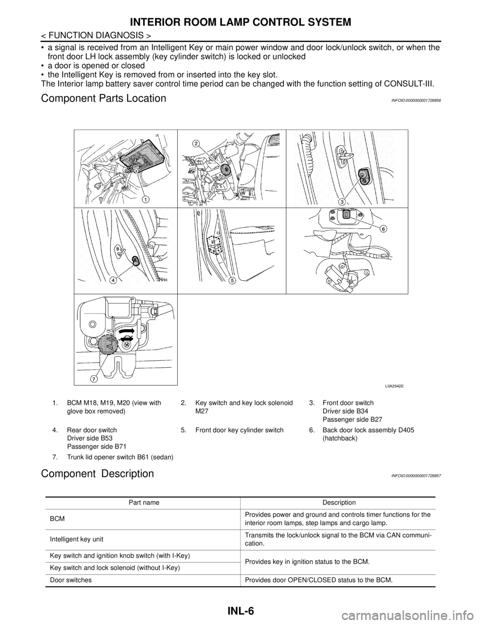
Component Parts LocationINFOID:0000000001728856
Component DescriptionINFOID:0000000001728857
1. BCM M18, M19, M20 (view with
glove box removed)2. Key switch and key lock solenoid
M273. Front door switch
Driver side B34
Passenger side B27
4. Rear door switch
Driver side B53
Passenger side B715. Front door key cylinder switch 6. Back door lock assembly D405
(hatchback)
7. Trunk lid opener switch B61 (sedan)
LIIA2942E
Part name Description
BCMProvides power and ground and controls timer functions for the
interior room lamps, step lamps and cargo lamp.
Intelligent key unitTransmits the lock/unlock signal to the BCM via CAN communi-
cation.
Key switch and ignition knob switch (with I-Key)
Provides key in ignition status to the BCM.
Key switch and lock solenoid (without I-Key)
Door switches Provides door OPEN/CLOSED status to the BCM.
Page 4361 of 5883

MWI-54
< ECU DIAGNOSIS >
COMBINATION METER
DTC Index
INFOID:0000000001374709
NOTE:
“TIME” indicates the following.
0: Indicates that a malfunction is detected at present.
1-63: Indicates that a malfunction was detected in the past. (Displays number of ignition switch OFF → ON
cycles after malfunction is detected. Self-diagnosis result is erased when “63” is exceeded.)
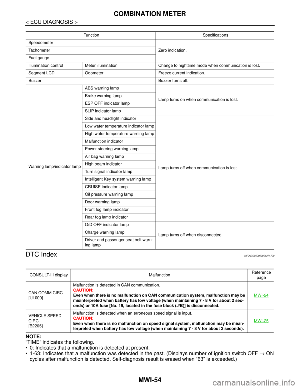
Function Specifications
Speedometer
Zero indication. Tachometer
Fuel gauge
Illumination control Meter illumination Change to nighttime mode when communication is lost.
Segment LCD Odometer Freeze current indication.
Buzzer Buzzer turns off.
Warning lamp/indicator lampABS warning lamp
Lamp turns on when communication is lost. Brake warning lamp
ESP OFF indicator lamp
SLIP indicator lamp
Side and headlight indicator
Lamp turns off when communication is lost. Low water temperature indicator lamp
High water temperature warning lamp
Malfunction indicator
Power steering warning lamp
Air bag warning lamp
High beam indicator
Turn signal indicator lamp
Intelligent Key system warning lamp
CRUISE indicator lamp
Oil pressure warning lamp
Door warning lamp
Front fog lamp indicator
Rear fog lamp indicator
O/D OFF indicator lamp
Lamp turns off when disconnected. Charge warning lamp
Driver and passenger seat belt warn-
ing lamp
CONSULT-III display MalfunctionReference
page
CAN COMM CIRC
[U1000]Malfunction is detected in CAN communication.
CAUTION:
Even when there is no malfunction on CAN communication system, malfunction may be
misinterpreted when battery has low voltage (when maintaining 7 - 8 V for about 2 sec-
onds) or 10A fuse [No. 19, located in the fuse block (J/B)] is disconnected.MWI-24
VEHICLE SPEED
CIRC
[B2205]Malfunction is detected when an erroneous speed signal is input.
CAUTION:
Even when there is no malfunction on speed signal system, malfunction may be misin-
terpreted when battery has low voltage (when maintaining 7 - 8 V for about 2 seconds). MWI-25
Page 4640 of 5883
![NISSAN TIIDA 2007 Service Repair Manual DIAGNOSIS SYSTEM (BCM)
SEC-15
< FUNCTION DIAGNOSIS >[WITH INTELLIGENT KEY SYSTEM]
C
D
E
F
G
H
I
J
L
MA
B
SEC
N
O
P
DIAGNOSIS SYSTEM (BCM)
COMMON ITEM
COMMON ITEM : CONSULT-III Function (BCM - COMMON I NISSAN TIIDA 2007 Service Repair Manual DIAGNOSIS SYSTEM (BCM)
SEC-15
< FUNCTION DIAGNOSIS >[WITH INTELLIGENT KEY SYSTEM]
C
D
E
F
G
H
I
J
L
MA
B
SEC
N
O
P
DIAGNOSIS SYSTEM (BCM)
COMMON ITEM
COMMON ITEM : CONSULT-III Function (BCM - COMMON I](/manual-img/5/57395/w960_57395-4639.png)
DIAGNOSIS SYSTEM (BCM)
SEC-15
< FUNCTION DIAGNOSIS >[WITH INTELLIGENT KEY SYSTEM]
C
D
E
F
G
H
I
J
L
MA
B
SEC
N
O
P
DIAGNOSIS SYSTEM (BCM)
COMMON ITEM
COMMON ITEM : CONSULT-III Function (BCM - COMMON ITEM)INFOID:0000000001404046
APPLICATION ITEM
CONSULT-III performs the following functions via CAN communication with BCM.
SYSTEM APPLICATION
BCM can perform the following functions for each system.
NOTE:
It can perform the diagnosis modes except the following for all sub system selection items.
IMMU
IMMU : CONSULT-III Function (BCM - IMMU)INFOID:0000000001404047
APPLICATION ITEM
CONSULT-III performs the following functions via CAN communication with BCM.
Diagnosis mode Function Description
WORK SUPPORT Changes the setting for each system function.
SELF-DIAG RESULTS Displays the diagnosis results judged by BCM. Refer to XX-XX, "*****"
.
CAN DIAG SUPPORT MNTR Monitors the reception status of CAN communication viewed from BCM.
DATA MONITOR The BCM input/output signals are displayed.
ACTIVE TEST The signals used to activate each device are forcibly supplied from BCM.
ECU IDENTIFICATION The BCM part number is displayed.
CONFIGURATION Enables to read and save the vehicle specification.
Enables to write the vehicle specification when replacing BCM.
System Sub system selection itemDiagnosis mode
WORK SUPPORT DATA MONITOR ACTIVE TEST
—BCM×
Door lock DOOR LOCK×××
Rear window defogger REAR DEFOGGER××
Warning chime BUZZER××
Interior room lamp timer INT LAMP×××
Remote keyless entry system MULTI REMOTE ENT×××
Exterior lamp HEAD LAMP×××
Wiper and washer WIPER×××
Turn signal and hazard warning lamps FLASHER××
Air conditioner AIR CONDITONER×
Intelligent Key system INTELLIGENT KEY×
Combination switch COMB SW×
Immobilizer IMMU××
Interior room lamp battery saver BATTERY SAVER×××
Trunk open TRUNK×
Vehicle security system THEFT ALM×××
Signal buffer system SIGNAL BUFFER××
PTC heater system PTC HEATER××
Page 4643 of 5883
![NISSAN TIIDA 2007 Service Repair Manual SEC-18
< FUNCTION DIAGNOSIS >[WITH INTELLIGENT KEY SYSTEM]
DIAGNOSIS SYSTEM (INTELLIGENT KEY UNIT)
DIAGNOSIS SYSTEM (INTELLIGENT KEY UNIT)
CONSULT-III Function (INTELLIGENT KEY)INFOID:0000000001404049 NISSAN TIIDA 2007 Service Repair Manual SEC-18
< FUNCTION DIAGNOSIS >[WITH INTELLIGENT KEY SYSTEM]
DIAGNOSIS SYSTEM (INTELLIGENT KEY UNIT)
DIAGNOSIS SYSTEM (INTELLIGENT KEY UNIT)
CONSULT-III Function (INTELLIGENT KEY)INFOID:0000000001404049](/manual-img/5/57395/w960_57395-4642.png)
SEC-18
< FUNCTION DIAGNOSIS >[WITH INTELLIGENT KEY SYSTEM]
DIAGNOSIS SYSTEM (INTELLIGENT KEY UNIT)
DIAGNOSIS SYSTEM (INTELLIGENT KEY UNIT)
CONSULT-III Function (INTELLIGENT KEY)INFOID:0000000001404049
APPLICATION ITEM
CONSULT-III performs the following functions via CAN communication with Intelligent Key unit.
WORK SUPPORT
SELF-DIAG RESULT
Refer to SEC-71, "DTCIndex".
DATA MONITOR
Diagnosis mode Function Description
WORK SUPPORT Changes the setting for each system function.
SELF-DIAG RESULTS Displays the diagnosis results judged by Intelligent Key unit.
CAN DIAG SUPPORT MNTR Monitors the reception status of CAN communication viewed from Intelligent Key unit.
DATA MONITOR The Intelligent Key unit input/output signals are displayed.
ACTIVE TEST The signals used to activate each device are forcibly supplied from Intelligent Key unit.
ECU IDENTIFICATION The Intelligent Key unit part number is displayed.
Support item Description Selection item Condition
CONFIRM KEY FOB IDIt can check whether Intelligent Key ID code
is registered or not.——
TAKE OUT FROM WINDOW WARNTake away warning chime (from window)
mode can be changed.ON Active
OFF Inactive
LOW BATT OF KEY FOB WARNIntelligent Key low battery warning mode can
be changed.ON Active
OFF Inactive
KEYLESS FUNCTIONDoor lock function with Intelligent Key can be
changed.ON Active
OFF Inactive
ANSWER BACK FUNCTION Buzzer reminder operation can be changed.ON Active
OFF Inactive
SELECTIVE UNLOCK FUNCTION Anti-hijack mode can be changed.ON Active
OFF Inactive
HAZARD ANSWER BACKHazard reminder operation mode can be
changed.Refer to XX-XX, "*****"
.
ANSWER BACK WITH I-KEY LOCKBuzzer reminder operation (lock operation)
mode by each door request switch can be
changed. BUZZER Active
OFF Inactive
ANSWER BACK WITH I-KEY UNLOCKBuzzer reminder operation (unlock operation)
mode by each door request switch can be
changed.BUZZER Active
OFF Inactive
AUTO RELOCK TIMERAuto door lock operation mode can be
changed.OFF Inactive
2 min Active
ENGINE START BY I-KEYEngine start function (by Intelligent Key)
mode can be changed. ON Active
OFF Inactive
LOCK/UNLOCK BY I-KEYDoor lock function by door request switch can
be changed. ON Active
OFF Inactive
Page 4712 of 5883
![NISSAN TIIDA 2007 Service Repair Manual DIAGNOSIS SYSTEM (BCM)
SEC-87
< FUNCTION DIAGNOSIS >[WITHOUT INTELLIGENT KEY SYSTEM]
C
D
E
F
G
H
I
J
L
MA
B
SEC
N
O
P
DIAGNOSIS SYSTEM (BCM)
COMMON ITEM
COMMON ITEM : CONSULT-III Function (BCM - COMMO NISSAN TIIDA 2007 Service Repair Manual DIAGNOSIS SYSTEM (BCM)
SEC-87
< FUNCTION DIAGNOSIS >[WITHOUT INTELLIGENT KEY SYSTEM]
C
D
E
F
G
H
I
J
L
MA
B
SEC
N
O
P
DIAGNOSIS SYSTEM (BCM)
COMMON ITEM
COMMON ITEM : CONSULT-III Function (BCM - COMMO](/manual-img/5/57395/w960_57395-4711.png)
DIAGNOSIS SYSTEM (BCM)
SEC-87
< FUNCTION DIAGNOSIS >[WITHOUT INTELLIGENT KEY SYSTEM]
C
D
E
F
G
H
I
J
L
MA
B
SEC
N
O
P
DIAGNOSIS SYSTEM (BCM)
COMMON ITEM
COMMON ITEM : CONSULT-III Function (BCM - COMMON ITEM)INFOID:0000000001404165
APPLICATION ITEM
CONSULT-III performs the following functions via CAN communication with BCM.
SYSTEM APPLICATION
BCM can perform the following functions for each system.
NOTE:
It can perform the diagnosis modes except the following for all sub system selection items.
IMMU
IMMU : CONSULT-III Function (BCM - IMMU)INFOID:0000000001404166
APPLICATION ITEM
CONSULT-III performs the following functions via CAN communication with BCM.
Diagnosis mode Function Description
WORK SUPPORT Changes the setting for each system function.
SELF-DIAG RESULTS Displays the diagnosis results judged by BCM. Refer to XX-XX, "*****"
.
CAN DIAG SUPPORT MNTR Monitors the reception status of CAN communication viewed from BCM.
DATA MONITOR The BCM input/output signals are displayed.
ACTIVE TEST The signals used to activate each device are forcibly supplied from BCM.
ECU IDENTIFICATION The BCM part number is displayed.
CONFIGURATION Enables to read and save the vehicle specification.
Enables to write the vehicle specification when replacing BCM.
System Sub system selection itemDiagnosis mode
WORK SUPPORT DATA MONITOR ACTIVE TEST
—BCM×
Door lock DOOR LOCK×××
Rear window defogger REAR DEFOGGER××
Warning chime BUZZER××
Interior room lamp timer INT LAMP×××
Remote keyless entry system MULTI REMOTE ENT×××
Exterior lamp HEAD LAMP×××
Wiper and washer WIPER×××
Turn signal and hazard warning lamps FLASHER××
Air conditioner AIR CONDITONER×
Combination switch COMB SW×
Immobilizer IMMU××
Interior room lamp battery saver BATTERY SAVER×××
Trunk open TRUNK×
Vehicle security system THEFT ALM×××
Signal buffer system SIGNAL BUFFER××
PTC heater system PTC HEATER××