2007 NISSAN TIIDA Air filter
[x] Cancel search: Air filterPage 4276 of 5883

MA-36
< ON-VEHICLE MAINTENANCE >
ENGINE MAINTENANCE (MR18DE)
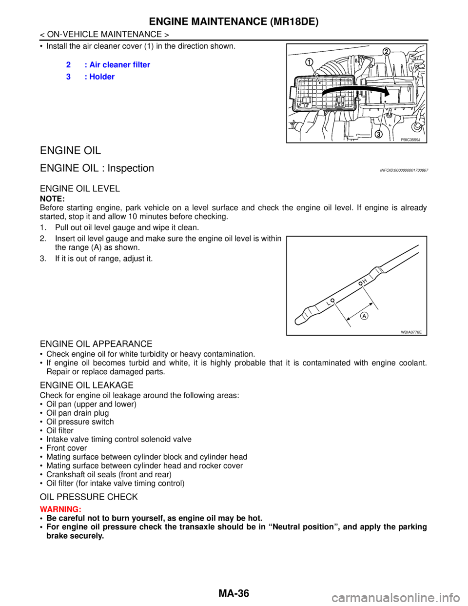
Install the air cleaner cover (1) in the direction shown.
ENGINE OIL
ENGINE OIL : InspectionINFOID:0000000001730867
ENGINE OIL LEVEL
NOTE:
Before starting engine, park vehicle on a level surface and check the engine oil level. If engine is already
started, stop it and allow 10 minutes before checking.
1. Pull out oil level gauge and wipe it clean.
2. Insert oil level gauge and make sure the engine oil level is within
the range (A) as shown.
3. If it is out of range, adjust it.
ENGINE OIL APPEARANCE
Check engine oil for white turbidity or heavy contamination.
If engine oil becomes turbid and white, it is highly probable that it is contaminated with engine coolant.
Repair or replace damaged parts.
ENGINE OIL LEAKAGE
Check for engine oil leakage around the following areas:
Oil pan (upper and lower)
Oil pan drain plug
Oil pressure switch
Oil filter
Intake valve timing control solenoid valve
Front cover
Mating surface between cylinder block and cylinder head
Mating surface between cylinder head and rocker cover
Crankshaft oil seals (front and rear)
Oil filter (for intake valve timing control)
OIL PRESSURE CHECK
WARNING:
Be careful not to burn yourself, as engine oil may be hot.
For engine oil pressure check the transaxle should be in “Neutral position”, and apply the parking
brake securely.2 : Air cleaner filter
3 : Holder
PBIC3559J
WBIA0776E
Page 4286 of 5883

MA-46
< ON-VEHICLE MAINTENANCE >
ENGINE MAINTENANCE (K9K)
AIR CLEANER FILTER
AIR CLEANER FILTER : Removal and InstallationINFOID:0000000001730875
REMOVAL
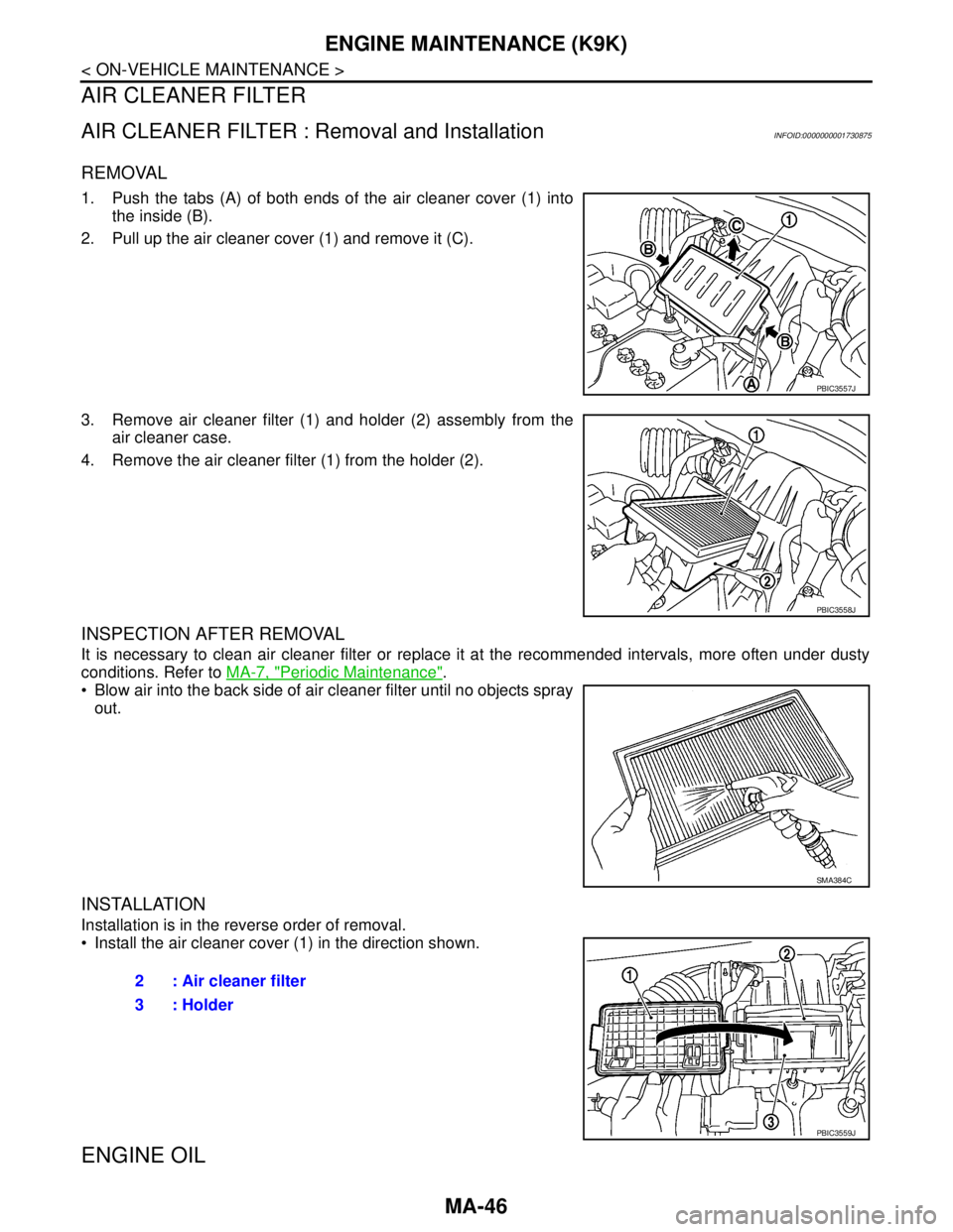
1. Push the tabs (A) of both ends of the air cleaner cover (1) into
the inside (B).
2. Pull up the air cleaner cover (1) and remove it (C).
3. Remove air cleaner filter (1) and holder (2) assembly from the
air cleaner case.
4. Remove the air cleaner filter (1) from the holder (2).
INSPECTION AFTER REMOVAL
It is necessary to clean air cleaner filter or replace it at the recommended intervals, more often under dusty
conditions. Refer to MA-7, "
Periodic Maintenance".
Blow air into the back side of air cleaner filter until no objects spray
out.
INSTALLATION
Installation is in the reverse order of removal.
Install the air cleaner cover (1) in the direction shown.
ENGINE OIL
PBIC3557J
PBIC3558J
SMA384C
2 : Air cleaner filter
3 : Holder
PBIC3559J
Page 4287 of 5883

ENGINE MAINTENANCE (K9K)
MA-47
< ON-VEHICLE MAINTENANCE >
C
D
E
F
G
H
I
J
K
L
MB
MAN
OA
ENGINE OIL : InspectionINFOID:0000000001730878
OIL LEVEL AND MUDDINESS
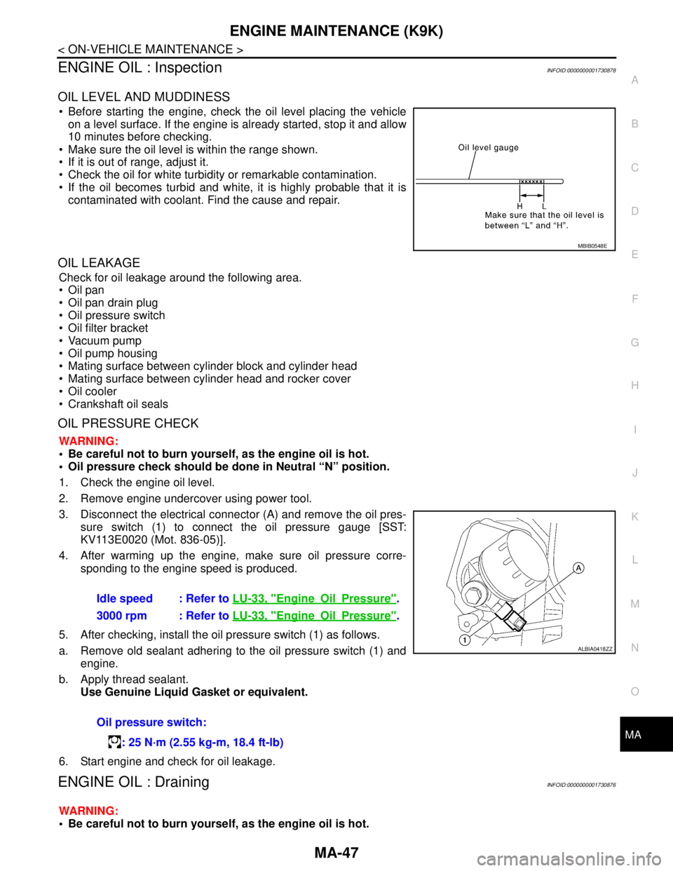
Before starting the engine, check the oil level placing the vehicle
on a level surface. If the engine is already started, stop it and allow
10 minutes before checking.
Make sure the oil level is within the range shown.
If it is out of range, adjust it.
Check the oil for white turbidity or remarkable contamination.
If the oil becomes turbid and white, it is highly probable that it is
contaminated with coolant. Find the cause and repair.
OIL LEAKAGE
Check for oil leakage around the following area.
Oil pan
Oil pan drain plug
Oil pressure switch
Oil filter bracket
Vacuum pump
Oil pump housing
Mating surface between cylinder block and cylinder head
Mating surface between cylinder head and rocker cover
Oil cooler
Crankshaft oil seals
OIL PRESSURE CHECK
WARNING:
Be careful not to burn yourself, as the engine oil is hot.
Oil pressure check should be done in Neutral “N” position.
1. Check the engine oil level.
2. Remove engine undercover using power tool.
3. Disconnect the electrical connector (A) and remove the oil pres-
sure switch (1) to connect the oil pressure gauge [SST:
KV113E0020 (Mot. 836-05)].
4. After warming up the engine, make sure oil pressure corre-
sponding to the engine speed is produced.
5. After checking, install the oil pressure switch (1) as follows.
a. Remove old sealant adhering to the oil pressure switch (1) and
engine.
b. Apply thread sealant.
Use Genuine Liquid Gasket or equivalent.
6. Start engine and check for oil leakage.
ENGINE OIL : DrainingINFOID:0000000001730876
WARNING:
Be careful not to burn yourself, as the engine oil is hot.
MBIB0548E
Idle speed : Refer to LU-33, "EngineOilPressure".
3000 rpm : Refer to LU-33, "
EngineOilPressure".
Oil pressure switch:
: 25 N·m (2.55 kg-m, 18.4 ft-lb)
ALBIA0418ZZ
Page 4290 of 5883

MA-50
< ON-VEHICLE MAINTENANCE >
CHASSIS AND BODY MAINTENANCE
CHASSIS AND BODY MAINTENANCE
Air Conditioner FilterINFOID:0000000001730893
1. Remove the instrument lower finisher and instrument lower cover (LH) for LHD only. Refer to IP-23, "Dis-
assembly and Assembly".
2. Remove the glove box assembly and instrument lower cover (RH) for RHD only. Refer to IP-23, "
Disas-
sembly and Assembly".
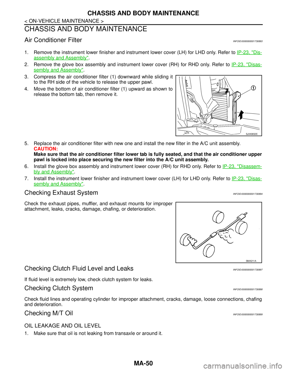
3. Compress the air conditioner filter (1) downward while sliding it
to the RH side of the vehicle to release the upper pawl.
4. Move the bottom of air conditioner filter (1) upward as shown to
release the bottom tab, then remove it.
5. Replace the air conditioner filter with new one and install the new filter in the A/C unit assembly.
CAUTION:
Make sure that the air conditioner filter lower tab is fully seated, and that the air conditioner upper
pawl is locked into place securing the new filter into the A/C unit assembly.
6. Install the glove box assembly and instrument lower cover (RH) for RHD only. Refer to IP-23, "
Disassem-
bly and Assembly".
7. Install the instrument lower finisher and instrument lower cover (LH) for LHD only. Refer to IP-23, "
Disas-
sembly and Assembly".
Checking Exhaust SystemINFOID:0000000001730894
Check the exhaust pipes, muffler, and exhaust mounts for improper
attachment, leaks, cracks, damage, chafing, or deterioration.
Checking Clutch Fluid Level and LeaksINFOID:0000000001730897
If fluid level is extremely low, check clutch system for leaks.
Checking Clutch SystemINFOID:0000000001730898
Check fluid lines and operating cylinder for improper attachment, cracks, damage, loose connections, chafing
and deterioration.
Checking M/T OilINFOID:0000000001730899
OIL LEAKAGE AND OIL LEVEL
1. Make sure that oil is not leaking from transaxle or around it.
SJIA0652E
SMA211A
Page 5092 of 5883
![NISSAN TIIDA 2007 Service Repair Manual TM-146
< SYMPTOM DIAGNOSIS >[TYPE 1 (4AT: RE4F03B)]
SYSTEM SYMPTOM
- Shift solenoid valve A
- Shift solenoid valve B
- Pilot valve
- Pilot filter
3. Disassemble A/T. Refer to TM-222, "
Disassembly".
NISSAN TIIDA 2007 Service Repair Manual TM-146
< SYMPTOM DIAGNOSIS >[TYPE 1 (4AT: RE4F03B)]
SYSTEM SYMPTOM
- Shift solenoid valve A
- Shift solenoid valve B
- Pilot valve
- Pilot filter
3. Disassemble A/T. Refer to TM-222, "
Disassembly".](/manual-img/5/57395/w960_57395-5091.png)
TM-146
< SYMPTOM DIAGNOSIS >[TYPE 1 (4AT: RE4F03B)]
SYSTEM SYMPTOM
- Shift solenoid valve A
- Shift solenoid valve B
- Pilot valve
- Pilot filter
3. Disassemble A/T. Refer to TM-222, "
Disassembly".
4. Check the following items:
- Forward clutch assembly. Refer to TM-267, "
Forward and Overrun Clutches".
- Low one-way clutch. Refer to TM-222, "
Disassembly".
- Forward one-way clutch. Refer to TM-278, "
Rear Internal Gear and Forward Clutch Hub".
- High clutch assembly. Refer to TM-262, "
High Clutch".
- Torque converter. Refer to TM-222, "
Disassembly".
- Oil pump assembly. Refer to TM-240, "
Oil Pump".
OK or NG
OK >> GO TO 8.
NG >> Repair or replace damaged parts.
6.CHECK A/T FLUID CONDITION
1. Remove oil pan. Refer to TM-213, "
Component".
2. Check A/T fluid condition. Refer to TM-171, "
Checking A/T Fluid".
OK or NG
OK >> GO TO 7.
NG >> GO TO 5.
7.DETECT MALFUNCTIONING ITEM
1. Remove control valve assembly. Refer to TM-191, "
Control Valve Assembly and Accumulators".
2. Check the following items:
- Shift valve A
- Shift valve B
- Shift solenoid valve A
- Shift solenoid valve B
- Pilot valve
- Pilot filter
OK or NG
OK >> GO TO 8.
NG >> Repair or replace damage parts.
8.CHECK SYMPTOM
Check again. Refer to TM-183, "
Cruise Test - Part 1".
OK or NG
OK >>INSPECTION END
NG >> GO TO 9.
9.CHECK TCM
1. Check TCM input/output signals. Refer to TM-22, "
Input/Output Signal of TCM".
2. If NG, recheck TCM pin terminals for damage or loose connection with harness connector.
OK or NG
OK >>INSPECTION END
NG >> Repair or replace damaged parts.
A/T Does Not Shift: D1→ D2or Does Not Kickdown: D4→ D2INFOID:0000000001696250
SYMPTOM:
A/T does not shift from D
1 to D2 at the specified speed on “Cruise Test — Part 1”.
A/T does not shift from D
4 to D2 when depressing accelerator pedal fully at the specified speed on
“Cruise Test — Part 2”.
1.CHECK SYMPTOM
Check symptom. Refer to TM-181, "
Check at Idle" and TM-183, "Cruise Test - Part 1".
Are
“Vehicle Dose Not Creep Forward in “D”, “2” or “1” Position” and “Vehicle Cannot Be Started from D1” OK?
Page 5093 of 5883
![NISSAN TIIDA 2007 Service Repair Manual SYSTEM SYMPTOM
TM-147
< SYMPTOM DIAGNOSIS >[TYPE 1 (4AT: RE4F03B)]
C
E
F
G
H
I
J
K
L
MA
B
TM
N
O
P
YES >> GO TO 2.
NG >> GO TO TM-144, "
Vehicle Does Not Creep Forward in "D", "2" or "1" Position" and NISSAN TIIDA 2007 Service Repair Manual SYSTEM SYMPTOM
TM-147
< SYMPTOM DIAGNOSIS >[TYPE 1 (4AT: RE4F03B)]
C
E
F
G
H
I
J
K
L
MA
B
TM
N
O
P
YES >> GO TO 2.
NG >> GO TO TM-144, "
Vehicle Does Not Creep Forward in "D", "2" or "1" Position" and](/manual-img/5/57395/w960_57395-5092.png)
SYSTEM SYMPTOM
TM-147
< SYMPTOM DIAGNOSIS >[TYPE 1 (4AT: RE4F03B)]
C
E
F
G
H
I
J
K
L
MA
B
TM
N
O
P
YES >> GO TO 2.
NG >> GO TO TM-144, "
Vehicle Does Not Creep Forward in "D", "2" or "1" Position" and TM-145, "Vehi-
cle Cannot Be Started from D1".
2.CHECK A/T POSITION
Check A/T position. Refer to TM-204, "
Checking of A/T Position".
OK or NG
OK >> GO TO 3.
NG >> Adjust A/T position. Refer to TM-204, "
Adjustment of A/T Position".
3.CHECK VEHICLE SPEED SENSOR·A/T AND VEHICLE SPEED SENSOR·MTR CIRCUIT
Check vehicle speed sensor·A/T (revolution sensor) and vehicle speed sensor·MTR circuit. Refer to XX-XX,
"*****" (type 1) or XX-XX, "*****" (type 2) and XX-XX, "*****" (type 1) or XX-XX, "*****" (type 2).
OK or NG
OK >> GO TO 4.
NG >> Repair or replace vehicle speed sensor·A/T (revolution sensor) and vehicle speed sensor·MTR
circuits.
4.CHECK ACCELERATOR PEDAL POSITION SENSOR
Check accelerator pedal position sensor. Refer to EC-297, "
Description" (type 1) or EC-583, "Description"
(type 2).
OK or NG
OK >> GO TO 5.
NG >> Repair or replace accelerator pedal position sensor.
5.CHECK A/T FLUID CONDITION
1. Remove oil pan. Refer to TM-213, "
Component".
2. Check A/T fluid condition. Refer to TM-171, "
Checking A/T Fluid".
OK or NG
OK >> GO TO 7.
NG >> GO TO 6.
6.DETECT MALFUNCTIONING ITEM
1. Remove control valve. Refer to TM-191, "
Control Valve Assembly and Accumulators".
2. Check the following items:
- Shift valve A
- Shift valve B
- Shift solenoid valve A
- Shift solenoid valve B
- Pilot valve
- Pilot filter
3. Disassemble A/T. Refer to TM-222, "
Disassembly".
4. Check the following items:
- Servo piston assembly
- Brake band
OK or NG
OK >> GO TO 8.
NG >> Repair or replace damaged parts.
7.DETECT MALFUNCTIONING ITEM
1. Remove control valve. Refer to TM-191, "
Control Valve Assembly and Accumulators".
2. Check the following items:
- Shift valve A
- Shift valve B
- Shift solenoid valve A
- Shift solenoid valve B
- Pilot valve
- Pilot filter
Page 5095 of 5883
![NISSAN TIIDA 2007 Service Repair Manual SYSTEM SYMPTOM
TM-149
< SYMPTOM DIAGNOSIS >[TYPE 1 (4AT: RE4F03B)]
C
E
F
G
H
I
J
K
L
MA
B
TM
N
O
P
6.DETECT MALFUNCTIONING ITEM
1. Remove control valve assembly. Refer to TM-191, "
Control Valve Assem NISSAN TIIDA 2007 Service Repair Manual SYSTEM SYMPTOM
TM-149
< SYMPTOM DIAGNOSIS >[TYPE 1 (4AT: RE4F03B)]
C
E
F
G
H
I
J
K
L
MA
B
TM
N
O
P
6.DETECT MALFUNCTIONING ITEM
1. Remove control valve assembly. Refer to TM-191, "
Control Valve Assem](/manual-img/5/57395/w960_57395-5094.png)
SYSTEM SYMPTOM
TM-149
< SYMPTOM DIAGNOSIS >[TYPE 1 (4AT: RE4F03B)]
C
E
F
G
H
I
J
K
L
MA
B
TM
N
O
P
6.DETECT MALFUNCTIONING ITEM
1. Remove control valve assembly. Refer to TM-191, "
Control Valve Assembly and Accumulators".
2. Check the following items:
- Shift valve B
- Shift solenoid valve B
- Pilot valve
- Pilot filter
3. Disassemble A/T. Refer to TM-222, "
Disassembly".
4. Check the following items:
- Servo piston assembly
- High clutch assembly. Refer to TM-262, "
High Clutch".
- Oil pump assembly. Refer to TM-240, "
Oil Pump".
OK or NG
OK >> GO TO 8.
NG >> Repair or replace damaged parts.
7.DETECT MALFUNCTIONING ITEM
1. Remove control valve assembly. Refer to TM-191, "
Control Valve Assembly and Accumulators".
2. Check the following items:
- Shift valve B
- Shift solenoid valve B
- Pilot valve
- Pilot filter
OK or NG
OK >> GO TO 8.
NG >> Repair or replace damaged parts.
8.CHECK SYMPTOM
Check again. Refer to TM-183, "
Cruise Test - Part 1" and TM-185, "Cruise Test - Part 2".
OK or NG
OK >>INSPECTION END
NG >> GO TO 9.
9.CHECK TCM
1. Check TCM input/output signal. Refer to TM-22, "
Input/Output Signal of TCM".
2. If NG, recheck TCM pin terminals for damage or loose connection with harness connector.
OK or NG
OK >>INSPECTION END
NG >> Repair or replace damaged parts.
A/T Does Not Shift: D3→ D4INFOID:0000000001696252
SYMPTOM:
A/T does not shift from D
3 to D4 at the specified speed on “Cruise Test — Part 1” and “Cruise Test —
Part 2”.
A/T must be warm before D
3 to D4 shift will occur.
1.CHECK SYMPTOM
Check symptom. Refer to TM-181, "
Check at Idle" and TM-183, "Cruise Test - Part 1".
Are
“Vehicle Does Not Creep Forward in “D”, “2” or “1” Position” and “Vehicle Cannot Be Started from D1” OK?
YES >> GO TO 2.
NO >> Go to TM-144, "
Vehicle Does Not Creep Forward in "D", "2" or "1" Position" and TM-145, "Vehicle
Cannot Be Started from D1".
2.CHECK SELF-DIAGNOSTIC RESULTS
Perform self-diagnosis. Refer to XX-XX, "*****"
or TM-38, "Diagnosis Procedure without CONSULT-III".
Is any malfunction detected by self-diagnostic results?
YES >> Check the malfunctioning system. Refer to XX-XX, "*****" or XX-XX, "*****".
Page 5096 of 5883
![NISSAN TIIDA 2007 Service Repair Manual TM-150
< SYMPTOM DIAGNOSIS >[TYPE 1 (4AT: RE4F03B)]
SYSTEM SYMPTOM
NO >> GO TO 3.
3.CHECK ACCELERATOR PEDAL POSITION SENSOR
Check accelerator pedal position sensor. Refer to EC-297, "
Description" (ty NISSAN TIIDA 2007 Service Repair Manual TM-150
< SYMPTOM DIAGNOSIS >[TYPE 1 (4AT: RE4F03B)]
SYSTEM SYMPTOM
NO >> GO TO 3.
3.CHECK ACCELERATOR PEDAL POSITION SENSOR
Check accelerator pedal position sensor. Refer to EC-297, "
Description" (ty](/manual-img/5/57395/w960_57395-5095.png)
TM-150
< SYMPTOM DIAGNOSIS >[TYPE 1 (4AT: RE4F03B)]
SYSTEM SYMPTOM
NO >> GO TO 3.
3.CHECK ACCELERATOR PEDAL POSITION SENSOR
Check accelerator pedal position sensor. Refer to EC-297, "
Description" (type 1) or EC-583, "Description"
(type 2).
OK or NG
OK >> GO TO 4.
NG >> Repair or replace accelerator pedal position sensor.
4.CHECK A/T FLUID CONDITION
1. Remove oil pan. Refer to TM-213, "
Component".
2. Check A/T fluid condition. Refer to TM-171, "
Checking A/T Fluid".
OK or NG
OK >> GO TO 6.
NG >> GO TO 5.
5.DETECT MALFUNCTIONING ITEM
1. Remove control valve assembly. Refer to TM-191, "
Control Valve Assembly and Accumulators".
2. Check the following items:
- Shift valve A
- Overrun clutch control valve
- Shift solenoid valve A
- Overrun clutch solenoid valve
- Pilot valve
- Pilot filter
3. Disassemble A/T. Refer to TM-222, "
Disassembly".
4. Check the following items:
- Servo piston assembly
- Brake band
- Torque converter. Refer to TM-222, "
Disassembly".
- Oil pump assembly. Refer to TM-240, "
Oil Pump".
OK or NG
OK >> GO TO 7.
NG >> Repair or replace damaged parts.
6.DETECT MALFUNCTIONING ITEM
1. Remove control valve assembly. Refer to TM-191, "
Control Valve Assembly and Accumulators".
2. Check the following items:
- Shift valve A
- Overrun clutch control valve
- Shift solenoid valve A
- Pilot valve
- Pilot filter
OK or NG
OK >> GO TO 7.
NG >> Repair or replace damaged parts.
7.CHECK SYMPTOM
Check again. Refer to TM-183, "
Cruise Test - Part 1" and TM-185, "Cruise Test - Part 2".
OK or NG
OK >>INSPECTION END
NG >> GO TO 8.
8.CHECK TCM
1. Check TCM input/output signals. Refer to TM-22, "
Input/Output Signal of TCM".
2. If NG, recheck TCM pin terminals for damage or loose connection with harness connector.
OK or NG
OK >>INSPECTION END