2007 NISSAN QASHQAI start stop button
[x] Cancel search: start stop buttonPage 183 of 297

Downloaded from www.Manualslib.com manuals search engine Shift lock release
j
1LHD models
j2RHD models
jA Shift lock release button
If the battery charge is low or discharged, the selec-
tor lever may not move from the P (Park) position
even with the brake pedal depressed and the selec-
tor lever button pushed.
To move the selector lever, perform the following
procedure:
1. Models with Intelligent Key system:
Place the ignition switch in the “OFF” or LOCK
position.
Models without Intelligent Key system:
Place the ignition switch in the LOCK position,
and remove the key if it is inserted.
2. Apply the handbrake.
3. Push down the shift lock release button
jA.Use
a suitable tool.
4. Push and hold the selector lever button and move the selector lever to the N (Neutral) position while
holding down the shift lock release button.
Place the ignition switch in the ON position to un-
lock the steering wheel. The vehicle may be moved
to the desired location. For models with Intelligent Key system: If the battery
is discharged completely, the steering wheel cannot
be unlocked. Do not move the vehicle with the steer-
ing wheel locked.
If the selector lever cannot be moved out of the P
(Park) position, have a NISSAN dealer or qualified
workshop check the CVT system as soon as pos-
sible.
WARNING
If the selector lever cannot be moved from the P
(Park) position while the engine is running and
the brake pedal is depressed, the stop lights may
not work. Malfunctioning stop lights could cause
an accident injuring yourself and others.
High fluid temperature protection mode
This transmission has a high fluid temperature pro-
tection mode. If the fluid temperature becomes too
high (for example, when climbing steep grades in
high temperature with heavy loads, such as when
towing a trailer), engine power and, under some
conditions, vehicle speed will be decreased auto-
matically to reduce the chance of transmission dam-
age. Vehicle speed can be controlled with the ac-
celerator pedal, but engine and vehicle speed may
be limited.
Fail-safe
When the fail-safe operation occurs, the CVT will
not be shifted to the selected driving position.
If the vehicle is driven under extreme conditions,
such as excessive wheel spinning and subse- quent hard braking, the fail-safe system may be
activated. This will occur even if all electrical cir-
cuits are functioning properly. In this case, place
the ignition switch in the “OFF” position and wait
for 10 seconds. Then turn the ignition switch back
to the ON position. The vehicle should return to
its normal operating condition. If it does not re-
turn to its normal operating condition, have a
NISSAN dealer or qualified workshop check the
transmission and repair it if necessary.
WARNING
When the fail-safe operation occurs, vehicle
speed may be gradually reduced. The reduced
speed may be lower than other traffic, which
could increase the chance of a collision. Be es-
pecially careful when driving. If necessary, pull to
the side of the road at a safe place and allow the
transmission to return to normal operation, or
have it repaired if necessary.
5-20Starting and driving
Page 185 of 297

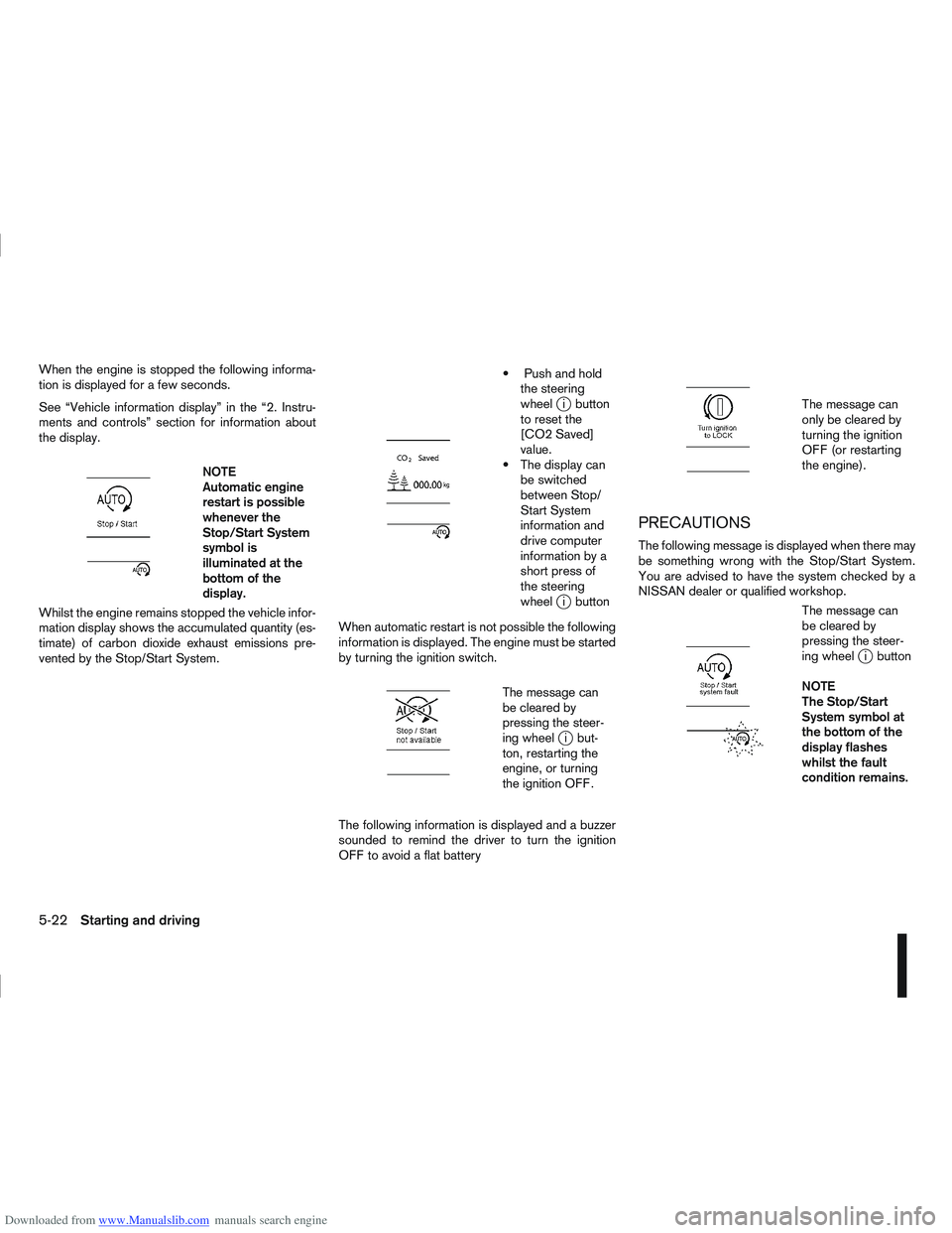
Downloaded from www.Manualslib.com manuals search engine When the engine is stopped the following informa-
tion is displayed for a few seconds.
See “Vehicle information display” in the “2. Instru-
ments and controls” section for information about
the display.
m
NOTE
Automatic engine
restart is possible
whenever the
Stop/Start System
symbol is
illuminated at the
bottomofthe
display.
Whilst the engine remains stopped the vehicle infor-
mation display shows the accumulated quantity (es-
timate) of carbon dioxide exhaust emissions pre-
vented by the Stop/Start System.
m
Push and hold the steering
wheel
ji button
to reset the
[CO2 Saved]
value.
The display can be switched
between Stop/
Start System
information and
drive computer
information by a
short press of
the steering
wheel
ji button
When automatic restart is not possible the following
information is displayed. The engine must be started
by turning the ignition switch.
m
The message can
be cleared by
pressing the steer-
ing wheel
ji but-
ton, restarting the
engine, or turning
the ignition OFF.
The following information is displayed and a buzzer
sounded to remind the driver to turn the ignition
OFF to avoid a flat battery
m
The message can
only be cleared by
turning the ignition
OFF (or restarting
the engine).
PRECAUTIONS
The following message is displayed when there may
be something wrong with the Stop/Start System.
You are advised to have the system checked by a
NISSAN dealer or qualified workshop.
m
The message can
be cleared by
pressing the steer-
ing wheel
ji button
NOTE
The Stop/Start
System symbol at
the bottom of the
display flashes
whilst the fault
condition remains.
5-22Starting and driving
Page 186 of 297

Downloaded from www.Manualslib.com manuals search engine STOP/START SYSTEM OFF SWITCH
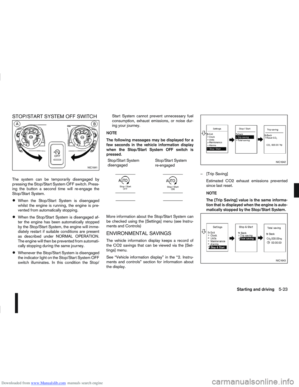
The system can be temporarily disengaged by
pressing the Stop/Start System OFF switch. Press-
ing the button a second time will re-engage the
Stop/Start System.
When the Stop/Start System is disengaged
whilst the engine is running, the engine is pre-
vented from automatically stopping.
When the Stop/Start System is disengaged af-
ter the engine has been automatically stopped
by the Stop/Start System, the engine will imme-
diately restart if suitable conditions are present
as described under NORMAL OPERATION.
The engine will then be prevented from automati-
cally stopping during the same journey.
Whenever the Stop/Start System is disengaged
the indicator light on the Stop/Start System OFF
switch illuminates. In this condition the Stop/Start System cannot prevent unnecessary fuel
consumption, exhaust emissions, or noise dur-
ing your journey.
NOTE
The following messages may be displayed for a
few seconds in the vehicle information display
when the Stop/Start System OFF switch is
pressed. Stop/Start System
disengaged
m
Stop/Start System
re-engaged
m
More information about the Stop/Start System can
be checked using the [Settings] menu (see Instru-
ments and Controls)
ENVIRONMENTAL SAVINGS
The vehicle information display keeps a record of
the CO2 savings that can be viewed via the [Set-
tings] menu.
See “Vehicle information display” in the “2. Instru-
ments and controls” section for information about
the display. – [Trip Saving]
Estimated CO2 exhaust emissions prevented
since last reset.
NOTE
The [Trip Saving] value is the same informa-
tion that is displayed when the engine is auto-
matically stopped by the Stop/Start System.
NIC1641
NIC1642
NIC1643
Starting and driving5-23
Page 289 of 297

Downloaded from www.Manualslib.com manuals search engine – Jump-starting ........................................................ 6-10, 8-19
– Precautions when starting and driving .............................. 5-3
– Push-starting ................................................................. 6-12
– Starting the engine ........................................................ 5-11
Steering
– Power steering system .................................................. 5-38
– Steering lock ............................................................ 5-7, 5-9
– Steering wheel adjustment ............................................. 3-16
– Steering wheel switches for hands-free telephonecontrol ........................................................................\
... 4-55
– Steering-wheel switch for audio control ......................... 4-43
– Steering-wheel switch for hands-free telephone control . 4-50
– Telephone button ........................................ 4-44, 4-52, 4-55
Stop/Start System ............................................................... 5-21
Storage ........................................................................\
....... 2-31
– Bottle holder .................................................................. 2-32
– Console box .................................................................. 2-32
– Cup holder .................................................................... 2-32
– Glove box ...................................................................... 2-31
– Map pockets ................................................................. 2-32
– Roof rail ........................................................................\
2-32
– Seat pockets ................................................................. 2-32
– Storage trays ................................................................. 2-31
– Sunglasses holder ......................................................... 2-32
Sun visors ........................................................................\
... 3-17
Sunshade
– Sunshade (Reinitialisation procedure) ............................ 2-37
– Sunshade operation ...................................................... 2-36
Super Lock system ............................................................... 3-9
– Emergency situations ....................................................... 3-9
– Power door lock switch ................................................. 3-11
Supplemental Restraint System (air bag system)
– Air bag system .............................................................. 1-13
– Air bag warning labels ................................................... 1-16
– Air bag warning light ...................................................... 1-16
– Front passenger air bag deactivate switch ..................... 1-17
– Front passenger air bag indicator light ........................... 1-17 Switch
– Defogger switch ............................................................ 2-23
– Fog light switch ............................................................. 2-26
– Headlight and turn signal switch .................................... 2-24
– Headlight cleaner switch ................................................ 2-28
– Power door lock switch ................................................. 3-10
– Wiper and washer switch .............................................. 2-21
T
Tachometer ........................................................................\
... 2-2
Temporary-use spare tyre ...................................................... 6-2
Three-point type seat belts .................................................... 1-9
Three-way catalyst (Petrol engine models) ............................. 5-4
Tilting steering wheel ........................................................... 3-16
Tonneau cover .................................................................... 2-33
Towing
– Recommended towing for four-wheel drive (4WD)models ........................................................................\
.. 6-14
– Recommended towing for two-wheel drive (2WD) models ........................................................................\
.. 6-14
– Tow bar Installation ....................................................... 5-36
– Tow truck towing ........................................................... 6-13
– Towing eye .................................................................... 6-15
– Towing precautions ....................................................... 6-13
– Trailer towing ................................................................ 5-35
Trailer
– Trailer brakes ................................................................ 5-36
– Trailer detection ............................................................. 5-36
– Trailer direction indicator light .......................................... 2-9
– Trailer towing ................................................................ 5-35
Transmission
– Automatic transmission (ignition knob) ...................... 5-7, 5-9
– Automatic transmission fluid (ATF) ................................. 8-14
– Continuously variable transmission (ignition knob) ..... 5-7, 5-9
– Continuously variable transmission fluid ......................... 8-14
10-8Index