2007 NISSAN PATHFINDER seat adjustment
[x] Cancel search: seat adjustmentPage 34 of 352

Unfastening the seat belts
s1To unfasten the seat belt, press the button on
the buckle. The seat belt automatically re-
tracts.
Checking seat belt operation
Seat belt retractors are designed to lock seat belt
movement by two separate methods:
cWhen the seat belt is pulled quickly from the
retractor.
cWhen the vehicle slows down rapidly.
To increase your confidence in the seat belts,
check the operation as follows.cGrasp the shoulder belt and pull forward
quickly. The retractor should lock and re-
strict further belt movement.
If the retractor does not lock during this check or
if you have any questions about seat belt opera-
tion, see a NISSAN dealer.
Shoulder belt height adjustment (front
and 2nd row outboard seats)
The shoulder belt anchor height should be ad-
justed to the position best for you. (See “Precau-
tions on seat belt usage” earlier in this section.)
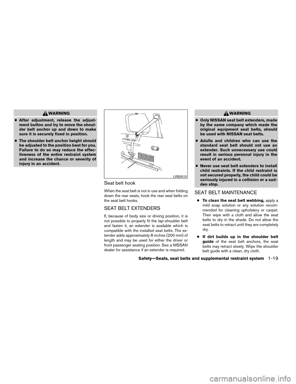
To adjust, pull out
s1the adjustment button and
move the shoulder belt anchor
s2to the desired
position, so the belt passes over the center of the
shoulder. The belt should be away from your face
and neck, but not falling off your shoulder. Re-
lease the adjustment button to lock the shoulder
belt anchor into position.
WRS0139
Front and 2nd row outboard seats
LRS0242
1-18Safety—Seats, seat belts and supplemental restraint system
ZREVIEW COPYÐ2007 Pathfinder(pat)
Owners ManualÐUSA_English(nna)
10/13/06Ðarosenma
X
Page 35 of 352

WARNING
cAfter adjustment, release the adjust-
ment button and try to move the shoul-
der belt anchor up and down to make
sure it is securely fixed in position.
cThe shoulder belt anchor height should
be adjusted to the position best for you.
Failure to do so may reduce the effec-
tiveness of the entire restraint system
and increase the chance or severity of
injury in an accident.
Seat belt hook
When the seat belt is not in use and when folding
down the rear seats, hook the rear seat belts on
the seat belt hooks.
SEAT BELT EXTENDERS
If, because of body size or driving position, it is
not possible to properly fit the lap-shoulder belt
and fasten it, an extender is available which is
compatible with the installed seat belts. The ex-
tender adds approximately 8 inches (200 mm) of
length and may be used for either the driver or
front passenger seating position. See a NISSAN
dealer for assistance if an extender is required.
WARNING
cOnly NISSAN seat belt extenders, made
by the same company which made the
original equipment seat belts, should
be used with NISSAN seat belts.
cAdults and children who can use the
standard seat belt should not use an
extender. Such unnecessary use could
result in serious personal injury in the
event of an accident.
cNever use seat belt extenders to install
child restraints. If the child restraint is
not secured properly, the child could be
seriously injured in a collision or a sud-
den stop.
SEAT BELT MAINTENANCE
cTo clean the seat belt webbing,apply a
mild soap solution or any solution recom-
mended for cleaning upholstery or carpet.
Then wipe with a cloth and allow the seat
belts to dry in the shade. Do not allow the
seat belts to retract until they are completely
dry.
cIf dirt builds up in the shoulder belt
guideof the seat belt anchors, the seat
belts may retract slowly. Wipe the shoulder
belt guide with a clean, dry cloth.
LRS0515
Safety—Seats, seat belts and supplemental restraint system1-19
ZREVIEW COPYÐ2007 Pathfinder(pat)
Owners ManualÐUSA_English(nna)
10/13/06Ðarosenma
X
Page 38 of 352

Several manufacturers offer child restraints for
infants and small children of various sizes. When
selecting any child restraint, keep the following
points in mind:
cChoose only a restraint with a label certifying
that it complies with Federal Motor Vehicle
Safety Standard 213 or Canadian Motor
Vehicle Safety Standard 213.
cCheck the child restraint in your vehicle to be
sure it is compatible with the vehicle’s seat
and seat belt system.
cIf the child restraint is compatible with your
vehicle, place your child in the child restraint
and check the various adjustments to be
sure the child restraint is compatible with
your child. Choose a child restraint that is
designed for your child’s height and weight.
Always follow all recommended procedures.
All U.S. states and Canadian provinces or
territories require that infants and small
children be restrained in an approved child
restraint at all times while the vehicle is
being operated.
LATCH (Lower Anchors and Tethers
for CHildren) SYSTEM
Your vehicle is equipped with special anchor
points that are used with LATCH (Lower Anchors
and Tethers for CHildren) system compatible
child restraints.
The LATCH anchor points are provided to install
child restraints in the 2nd row outboard seating
positions only. Do not attempt to install a child
restraint in the center position using the LATCH
anchors.
LATCH lower anchor point locations
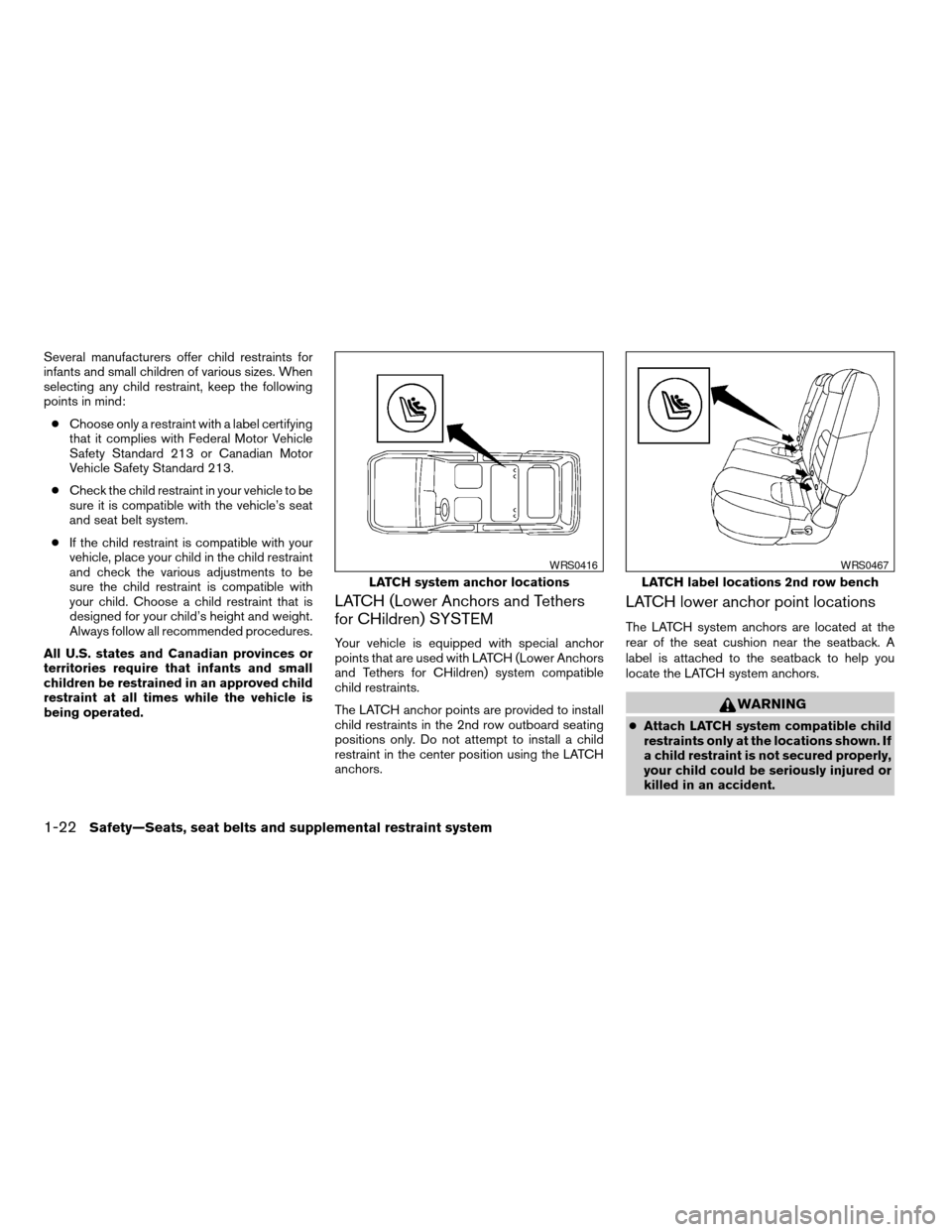
The LATCH system anchors are located at the
rear of the seat cushion near the seatback. A
label is attached to the seatback to help you
locate the LATCH system anchors.
WARNING
cAttach LATCH system compatible child
restraints only at the locations shown. If
a child restraint is not secured properly,
your child could be seriously injured or
killed in an accident.
LATCH system anchor locations
WRS0416
LATCH label locations 2nd row bench
WRS0467
1-22Safety—Seats, seat belts and supplemental restraint system
ZREVIEW COPYÐ2007 Pathfinder(pat)
Owners ManualÐUSA_English(nna)
10/13/06Ðarosenma
X
Page 52 of 352

cAfter placing the child in the booster
seat and fastening the seat belt, make
sure the shoulder portion of the belt is
away from the child’s face and neck and
the lap portion of the belt does not
cross the abdomen.
cDo not put the shoulder belt behind the
child or under the child’s arm. If you
must install a booster seat in the front
seat, see “Booster seat installation”
later in this section.
cWhen your booster seat is not in use,
keep it secured with a seat belt to pre-
vent it from being thrown around in
case of a sudden stop or accident.
CAUTION
Remember that a booster seat left in a
closed vehicle can become very hot.
Check the seating surface and buckles
before placing your child in the booster
seat.Booster seats of various sizes are offered by
several manufacturers. When selecting any
booster seat, keep the following points in mind:
cChoose only a booster seat with a label
certifying that it complies with Federal Motor
Vehicle Safety Standard 213 or Canadian
Motor Vehicle Safety Standard 213.
cCheck the booster seat in your vehicle to be
sure it is compatible with the vehicle’s seat
and seat belt system.
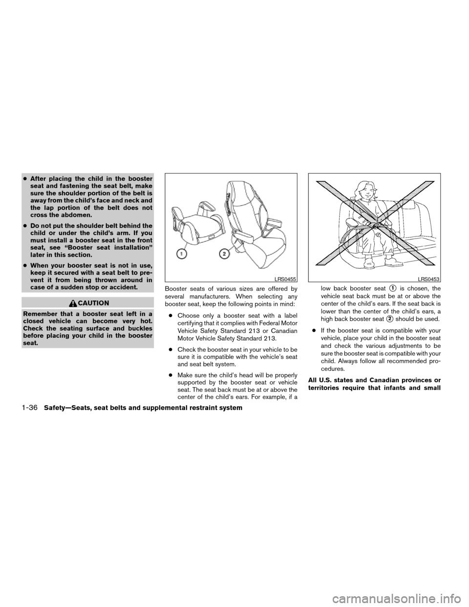
cMake sure the child’s head will be properly
supported by the booster seat or vehicle
seat. The seat back must be at or above the
center of the child’s ears. For example, if alow back booster seat
s1is chosen, the
vehicle seat back must be at or above the
center of the child’s ears. If the seat back is
lower than the center of the child’s ears, a
high back booster seat
s2should be used.
cIf the booster seat is compatible with your
vehicle, place your child in the booster seat
and check the various adjustments to be
sure the booster seat is compatible with your
child. Always follow all recommended pro-
cedures.
All U.S. states and Canadian provinces or
territories require that infants and small
LRS0455LRS0453
1-36Safety—Seats, seat belts and supplemental restraint system
ZREVIEW COPYÐ2007 Pathfinder(pat)
Owners ManualÐUSA_English(nna)
10/13/06Ðarosenma
X
Page 54 of 352

3. The booster seat should be positioned on
the vehicle seat so that it is stable. If neces-
sary, adjust or remove the head restraint to
obtain the correct booster seat fit. See
“Head restraint adjustment” earlier in this
section. If the head restraint is removed,
store it in a secure place. Be sure to install
the head restraint when the booster seat is
removed. If the seating position does not
have an adjustable head restraint and it is
interfering with the proper booster seat fit,
try another seating position or a different
booster seat.4. Position the lap portion of the seat belt low
and snug on the child’s hips. Be sure to
follow the booster seat manufacturer’s in-
structions for adjusting the belt routing.
5. Pull the shoulder belt portion of the seat belt
toward the retractor to take up extra slack.
Be sure the shoulder belt is positioned
across the top, middle portion of the child’s
shoulder. Be sure to follow the booster seat
manufacturer’s instructions for adjusting the
belt routing.
Rear center position
LRS0504
Rear outboard position
LRS0502
1-38Safety—Seats, seat belts and supplemental restraint system
ZREVIEW COPYÐ2007 Pathfinder(pat)
Owners ManualÐUSA_English(nna)
10/13/06Ðarosenma
X
Page 133 of 352

WARNING
cAlways have the doors locked while
driving. Along with the use of seat belts,
this provides greater safety in the event
of an accident by helping to prevent
persons from being thrown from the
vehicle. This also helps keep children
and others from unintentionally open-
ing the doors, and will help keep out
intruders.
cBefore opening any door, always look
for and avoid oncoming traffic.
cDo not leave children unattended inside
the vehicle. They could unknowingly ac-
tivate switches or controls. Unattended
children could become involved in seri-
ous accidents.
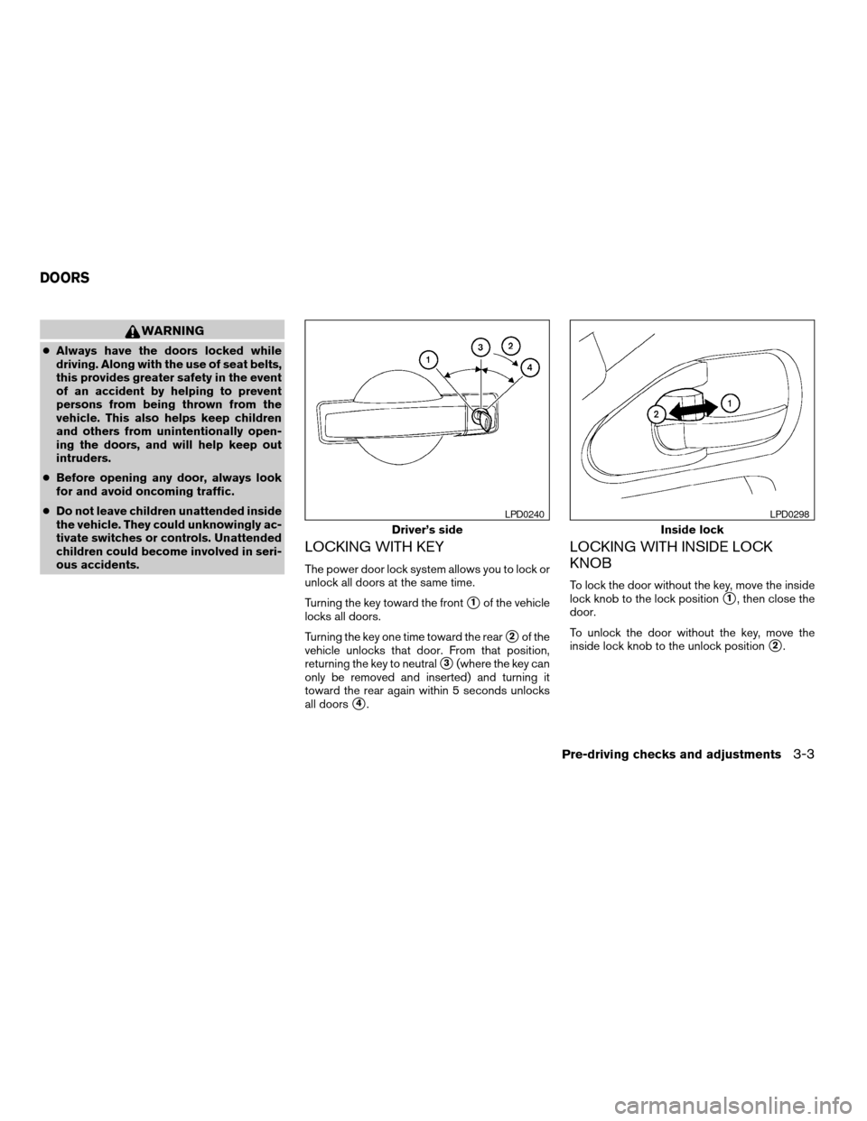
LOCKING WITH KEY
The power door lock system allows you to lock or
unlock all doors at the same time.
Turning the key toward the front
s1of the vehicle
locks all doors.
Turning the key one time toward the rear
s2of the
vehicle unlocks that door. From that position,
returning the key to neutral
s3(where the key can
only be removed and inserted) and turning it
toward the rear again within 5 seconds unlocks
all doors
s4.
LOCKING WITH INSIDE LOCK
KNOB
To lock the door without the key, move the inside
lock knob to the lock position
s1, then close the
door.
To unlock the door without the key, move the
inside lock knob to the unlock position
s2.
Driver’s side
LPD0240
Inside lock
LPD0298
DOORS
Pre-driving checks and adjustments3-3
ZREVIEW COPYÐ2007 Pathfinder(pat)
Owners ManualÐUSA_English(nna)
10/16/06Ðcathy
X
Page 147 of 352

The automatic drive positioner system has two
features:
cMemory storage function
cEntry/exit function
MEMORY STORAGE FUNCTION
Two positions for the driver’s seat, accelerator
and brake pedals, and outside mirrors can be
stored in the automatic drive positioner memory.
Follow these procedures to use the memory sys-
tem.
1. Set the automatic transmission selector le-
ver to the P (Park) position.
2. Turn the ignition ON.3. Adjust the driver’s seat, accelerator and
brake pedals, and outside mirrors to the
desired positions by manually operating
each adjusting switch. For additional infor-
mation, see “Seats” in the “Safety—Seats,
seat belts and supplemental restraint sys-
tem” section and “Pedal position adjust-
ment” and “Outside mirrors” earlier in this
section.
During this step, do not turn the ignition to
any position other than ON.
4. Push the SET switch and, within 5 seconds,
push the memory switch (1 or 2) fully for at
least 1 second.
The indicator light for the pushed memory
switch will come on and stay on for approxi-
mately 5 seconds after pushing the switch.
After the indicator light goes off, the se-
lected positions are stored in the selected
memory (1 or 2) .
If a new memory is stored in the same memory
switch, the previous memory will be deleted.
LPD0306
AUTOMATIC DRIVE POSITIONER (if
so equipped)
Pre-driving checks and adjustments3-17
ZREVIEW COPYÐ2007 Pathfinder(pat)
Owners ManualÐUSA_English(nna)
10/16/06Ðcathy
X
Page 148 of 352

Linking a keyfob to a stored memory
position
Each keyfob can be linked to a stored memory
position (memory switch 1 or 2) with the follow-
ing procedure.
1. Follow the steps for storing a memory posi-
tion.
2. While the indicator light for the memory
switch being set is illuminated for 5 sec-
onds, press the
button on the keyfob.
The indicator light will blink. After the indica-
tor light goes off, the keyfob is linked to that
memory setting.
With the key removed from the ignition switch,
press the
button on the keyfob. The driv-
er’s seat, accelerator and brake pedals, and out-
side mirrors will move to the memorized position.
NOTE:
If a new memory position is saved to the
memory switch, the keyfob automatically
re-links.
Confirming memory storage
cTurn the ignition ON and push the SET
switch. If the main memory has not been
stored, the indicator light will come on for
approximately 0.5 seconds. When thememory has stored the position, the indica-
tor light will stay on for approximately 5 sec-
onds.
cIf the battery cable is disconnected, or if the
fuse opens, the memory storage function will
be canceled and must be restarted before a
stored memory position can be set again.
Drive the vehicle over 25 MPH (40 km/h) to
restart the memory storage function. You
can also restart the memory storage function
using the following procedure.
1. Connect the battery cable or replace the
fuse.
2. Open and close the driver’s door more than
two times with the ignition key in the LOCK
position.
Once the memory storage function has been
restarted, you can store a memory position.
See “Memory storage function” earlier in this
section.
Selecting the memorized position
Set the automatic transmission selector lever to
the P (Park) position, then:
cWithin 45 seconds of opening the driver’s
door, push the memory switch (1 or 2) fully
for at least 1 second, orcTurn the ignition switch to the ON position
and push the memory switch (1 or 2) fully for
at least 1 second.
The driver’s seat, accelerator and brake pedals,
and outside mirrors will move to the memorized
position with the indicator light blinking, and then
the light will stay on for approximately 5 seconds.
ENTRY/EXIT FUNCTION
This system is designed so that the driver’s seat
will automatically move when the automatic
transmission selector lever is in the P (Park)
position. This allows the driver to get into and out
of the driver’s seat more easily.
The driver’s seat will slide backward:
cWhen the key is removed from the ignition
switch and the driver’s door is opened.
cWhen the driver’s door is opened with the
ignition key turned to LOCK.
cWhen the ignition key is turned from ACC to
LOCK with the driver’s door open.
The driver’s seat will return to the previous posi-
tion:
cWhen the key is inserted into the ignition
switch and the driver’s door is closed.
cWhen the driver’s door is closed with the key
turned to LOCK.
3-18Pre-driving checks and adjustments
ZREVIEW COPYÐ2007 Pathfinder(pat)
Owners ManualÐUSA_English(nna)
10/16/06Ðcathy
X