2007 NISSAN NOTE interior
[x] Cancel search: interiorPage 31 of 235

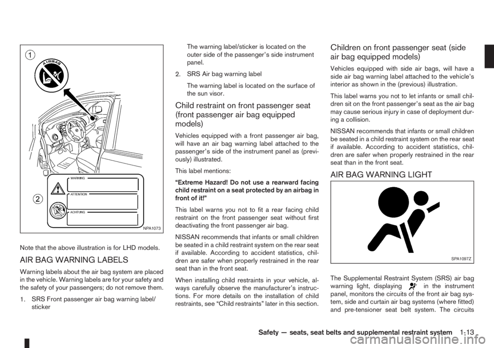
Note that the above illustration is for LHD models.
AIR BAG WARNING LABELS
Warning labels about the air bag system are placed
in the vehicle. Warning labels are for your safety and
the safety of your passengers; do not remove them.
1.SRS Front passenger air bag warning label/
stickerThe warning label/sticker is located on the
outer side of the passenger’s side instrument
panel.
2.SRS Air bag warning label
The warning label is located on the surface of
the sun visor.
Child restraint on front passenger seat
(front passenger air bag equipped
models)
Vehicles equipped with a front passenger air bag,
will have an air bag warning label attached to the
passenger’s side of the instrument panel as (previ-
ously) illustrated.
This label mentions:
“Extreme Hazard! Do not use a rearward facing
child restraint on a seat protected by an airbag in
front of it!”
This label warns you not to fit a rear facing child
restraint on the front passenger seat without first
deactivating the front passenger air bag.
NISSAN recommends that infants or small children
be seated in a child restraint system on the rear seat
if available. According to accident statistics, chil-
dren are safer when properly restrained in the rear
seat than in the front seat.
When installing child restraints in your vehicle, al-
ways carefully observe the manufacturer’s instruc-
tions. For more details on the installation of child
restraints, see “Child restraints” later in this section.
Children on front passenger seat (side
air bag equipped models)
Vehicles equipped with side air bags, will have a
side air bag warning label attached to the vehicle’s
interior as shown in the (previous) illustration.
This label warns you not to let infants or small chil-
dren sit on the front passenger’s seat as the air bag
may cause serious injury in case of deployment dur-
ing a collision.
NISSAN recommends that infants or small children
be seated in a child restraint system on the rear seat
if available. According to accident statistics, chil-
dren are safer when properly restrained in the rear
seat than in the front seat.
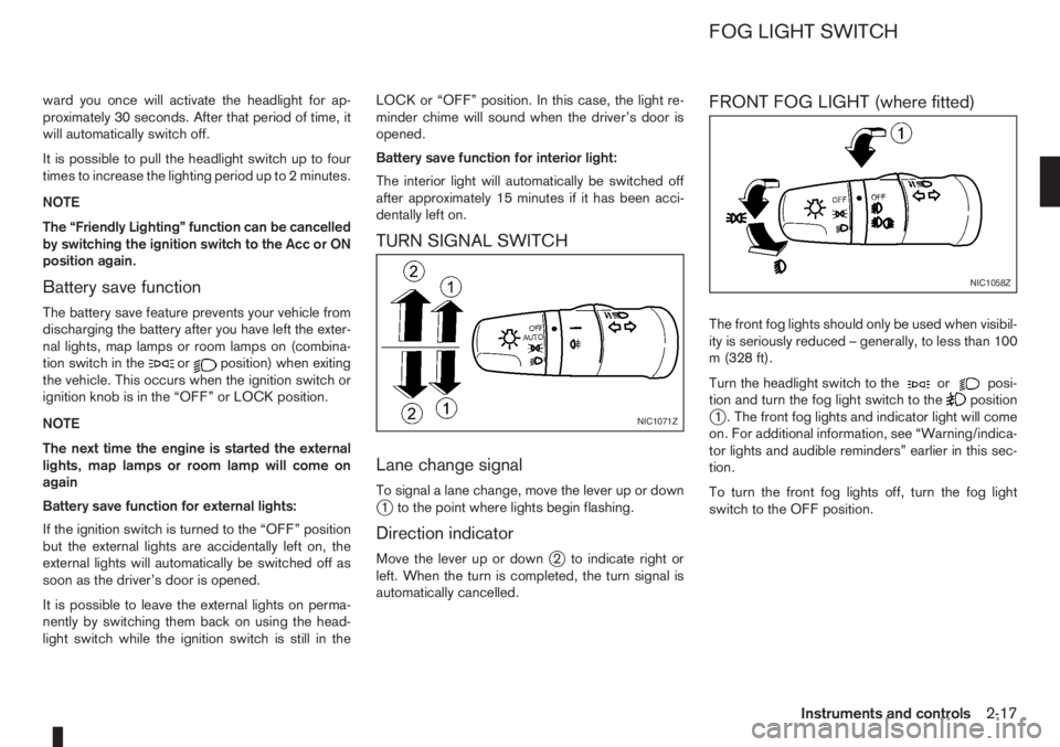
AIR BAG WARNING LIGHT
The Supplemental Restraint System (SRS) air bag
warning light, displayingin the instrument
panel, monitors the circuits of the front air bag sys-
tem, side and curtain air bag systems (where fitted)
and pre-tensioner seat belt system. The circuits
NPA1073
SPA1097Z
Safety — seats, seat belts and supplemental restraint system1-13
Page 43 of 235

2Instruments and controlsInstruments and controls
Meters and gauges .................................................. 2-2
Speedometer...................................................... 2-2
Tachometer ........................................................ 2-2
Fuel gauge ......................................................... 2-2
Combination meter display (LCD) ....................... 2-3
Odometer/twin trip odometer .............................. 2-3
Trip computer (where fitted)................................ 2-3
Outside temperature display ............................... 2-4
Engine oil level information (where fitted)............. 2-4
Digital clock ........................................................ 2-5
Warning/indicator lights and audible reminders ........ 2-7
Checking bulbs .................................................. 2-7
Warning lights .................................................... 2-7
Indicator lights .................................................... 2-11
Audible reminders............................................... 2-12
Wiper and washer switch ........................................ 2-13
Windscreen wiper and washer switch ................. 2-13
Rear window ...................................................... 2-14
Defogger switch ...................................................... 2-15
Rear window defogger ....................................... 2-15
Outside mirror defogger (where fitted) ................ 2-15
Headlight and turn signal switch............................... 2-16
Headlight switch ................................................. 2-16
Turn signal switch ............................................... 2-17
Fog light switch ....................................................... 2-17
Front fog light (where fitted) ................................ 2-17Rear fog light switch ........................................... 2-18
Headlight aiming control .......................................... 2-18
Headlight aiming control switch........................... 2-18
Hazard warning flasher switch ................................. 2-19
Horn ........................................................................ 2-19
Seat heating (where fitted) ....................................... 2-19
Power outlet ............................................................ 2-20
Storage ................................................................... 2-21
Glove box ........................................................... 2-21
Centre console storage box ................................ 2-22
Cup holder ......................................................... 2-22
Rear foldable tables (where fitted)....................... 2-23
Seat pockets (where fitted) ................................. 2-23
Convenience hook (where fitted)......................... 2-23
Under seat storage tray (where fitted) ................. 2-23
“Flexi-board” System (where fitted) ..................... 2-24
Utility hooks (where fitted)................................... 2-25
Power windows ....................................................... 2-25
Driver’s side main switch .................................... 2-26
Passenger’s side switch ..................................... 2-26
Automatic operation ............................................ 2-26
Interior lights ............................................................ 2-27
Room light .......................................................... 2-27
Map light (where fitted) ....................................... 2-28
Luggage compartment light ................................ 2-28
Page 59 of 235

ward you once will activate the headlight for ap-
proximately 30 seconds. After that period of time, it
will automatically switch off.
It is possible to pull the headlight switch up to four
times to increase the lighting period up to 2 minutes.
NOTE
The “Friendly Lighting” function can be cancelled
by switching the ignition switch to the Acc or ON
position again.
Battery save function
The battery save feature prevents your vehicle from
discharging the battery after you have left the exter-
nal lights, map lamps or room lamps on (combina-
tion switch in the
orposition) when exiting
the vehicle. This occurs when the ignition switch or
ignition knob is in the “OFF” or LOCK position.
NOTE
The next time the engine is started the external
lights, map lamps or room lamp will come on
again
Battery save function for external lights:
If the ignition switch is turned to the “OFF” position
but the external lights are accidentally left on, the
external lights will automatically be switched off as
soon as the driver’s door is opened.
It is possible to leave the external lights on perma-
nently by switching them back on using the head-
light switch while the ignition switch is still in theLOCK or “OFF” position. In this case, the light re-
minder chime will sound when the driver’s door is
opened.
Battery save function for interior light:
The interior light will automatically be switched off
after approximately 15 minutes if it has been acci-
dentally left on.
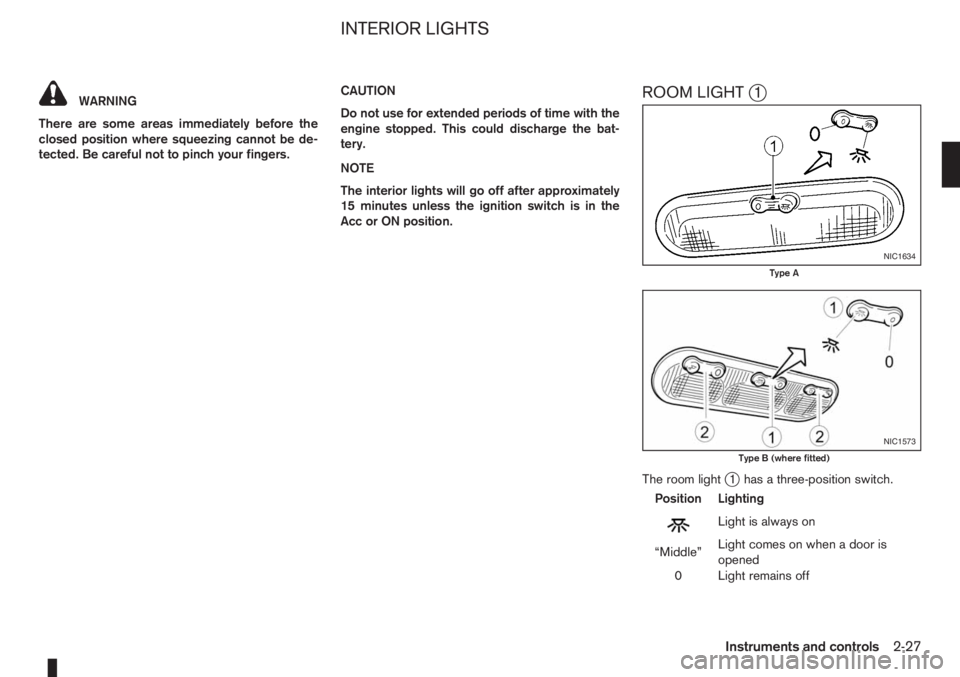
TURN SIGNAL SWITCH
Lane change signal
To signal a lane change, move the lever up or downj1 to the point where lights begin flashing.
Direction indicator
Move the lever up or downj2 to indicate right or
left. When the turn is completed, the turn signal is
automatically cancelled.
FRONT FOG LIGHT (where fitted)
The front fog lights should only be used when visibil-
ity is seriously reduced – generally, to less than 100
m (328 ft).
Turn the headlight switch to the
orposi-
tion and turn the fog light switch to thepositionj1 . The front fog lights and indicator light will come
on. For additional information, see “Warning/indica-
tor lights and audible reminders” earlier in this sec-
tion.
To turn the front fog lights off, turn the fog light
switch to the OFF position.NIC1071Z
NIC1058Z
FOG LIGHT SWITCH
Instruments and controls2-17
Page 62 of 235

5. When the vehicle’s interior has warmed-up, or
before you leave the vehicle, be sure to turn the
seat heater system off.
CAUTION
•Do not use the seat heater system for a long
period of time when the engine is not running,
otherwise the battery could run down.
•Do not put anything on the seat that insulates
the heat, such as a blanket, cushion, seat
cover, etc. Otherwise, the seat may overheat.
•Do not place anything hard or heavy on the
seat or pierce it with a pin or similar object.
This may damage the heater.
•Any liquid spilled on a heated seat should be
removed immediately with a dry cloth.
•When cleaning the seat, never use benzine,
thinner or any similar materials.
•If any abnormalities are found or the heating
does not operate, turn off the switch and have
the system checked by a NISSAN dealer or
qualified workshop.1.Power outlet
A.Front of the vehicle
The 12V (120 W) power outlet
j1 provides a high
output electrical power supply to operate devices
such as:
•pocket computer games
•personal stereo
•fans
CAUTION
•This power outlet is not designed for use with
a cigarette lighter unit.
•Use this power outlet with the engine running
(do not use for extended period of time with
the engine stopped or idling).
•When not in use, ensure that the cap is in-
serted. Do not allow water to contact the out-
let.
NIC1060Z
Front centre console
NIC1061Z
Rear centre console (where fitted)
NIC1485
Luggage compartment side panel (where fitted)
POWER OUTLET
2-20Instruments and controls
Page 69 of 235

WARNING
There are some areas immediately before the
closed position where squeezing cannot be de-
tected. Be careful not to pinch your fingers.CAUTION
Do not use for extended periods of time with the
engine stopped. This could discharge the bat-
tery.
NOTE
The interior lights will go off after approximately
15 minutes unless the ignition switch is in the
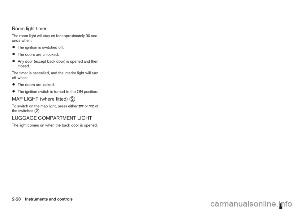
Acc or ON position.ROOM LIGHTj1
The room lightj1 has a three-position switch.
Position Lighting
mLightisalwayson
“Middle”Light comes on when a door is
opened
0 Light remains off
NIC1634
Type A
NIC1573
Type B (where fitted)
INTERIOR LIGHTS
Instruments and controls2-27
Page 70 of 235

Room light timer
The room light will stay on for approximately 30 sec-
onds when:
•The ignition is switched off.
•The doors are unlocked.
•Any door (except back door) is opened and then
closed.
The timer is cancelled, and the interior light will turn
off when:
•The doors are locked.
•The ignition switch is turned to the ON position.
MAP LIGHT (where fitted)j2
To switch on the map light, press eitherorof
the switchesj2.
LUGGAGE COMPARTMENT LIGHT
The light comes on when the back door is opened.
2-28Instruments and controls
Page 86 of 235

SIDE VENTS
The direction of the air flow can be adjusted byjA
opening,jB closing orjC adjusting.
CENTRE VENTS
The direction of the airflow can be adjustedjAand
the vents can be opened or closedjB.
: This symbol indicates that the vents are
closed.
: This symbol indicates that the vents are open.
WARNING
•The heater and air conditioner operate only
when the engine is running.
•Never leave children or adults who would nor-
mally require the support of others alone in
the vehicle. Pets should not be left alone ei-
ther. They could unknowingly activate
switches or controls and inadvertently
become involved in a serious accident and
injure themselves. On hot, sunny days, tem-
peratures in a closed vehicle could quickly
become high enough to cause severe or pos-
sibly fatal injuries to people or animals.
•Do not use the recirculation mode for long
periods as it may cause the interior air to be-
come stale and the windows to fog up.
•Do not adjust the heating and air conditioning
controls while driving so that full attention may
be given to vehicle operation.
NOTE
•Condensation forms inside the air condition-
ing unit when the air conditioner is running,
and is safely discharged underneath your ve-
hicle.
•Traces of water on the ground are therefore
normal.
NAA883Z
NAA884Z
VENTS HEATER AND AIR CONDITIONER
OPERATION
4-2Heater and air conditioner, and audio system
Page 87 of 235

MANUAL AIR CONDITIONER
1.Air flow control dial
2.Air intake lever
3.Temperature control dial
4.Air conditioner ON/OFF button (where fitted)
5.Fan speed control dial
Controls
Fan speed control dialm:
To switch the fan on or off and to control the fan
speed, turn the fan speed control dial clockwise to
increase the fan speed. To decrease the fan speed,
turn the fan speed control dial anticlockwise.
Temperature control dial:
Turn the temperature control dial to set the desired
air temperature from the vents and floor outlets.Air flow control dial:
Use this dial to manually select the air flow from the
air outlets as described below.
: Air flows from centre and side vents.
: Air flows from centre, side vents and floor
outlets.
: Air flows mainly from floor outlets.
: Air flows from the defogger outlets and floor
outlets.
: Air flows mainly from defogger outlets.
Air recirculation mode
m:
Move the air intake lever to the
position. To
recirculate interior air in the passenger compartment
in situations such as: driving on a dust raised road,
avoiding traffic fumes or having maximum cooling
from the air conditioner.Outside air mode
m:
Move the air intake lever to the
position to
draw outside air into the passenger compartment
for normal heating, ventilation or air conditioner op-
eration.
Heater operation
The heating function operates only after engine
warm-up.
Heating:
This mode is used to direct hot air from the floor out-
lets.
1. Move the air intake lever to the
position for
normal heating.
2. Turn the air flow control dial to the
position.
3. Turn the fan speed control dial to the desired fan
speed.
4. Turn the temperature control dial to the desired
position between the middle and the maximum
“HOT” (right) position.
For quick heating, select the air recirculation mode
position (
). Be sure to return to the outside air
mode position () for normal heating to avoid
window fog and stale interior air.
Ventilation:
This mode directs outside air from the side and
centre vents.
1. Move the air intake lever to the
position.
NAA1032Z
Manual air conditioner
Heater and air conditioner, and audio system4-3