Page 1090 of 2896
SHIFT CONTROL SYSTEM
CVT-193
D
E
F
G
H
I
J
K
L
MA
B
CVT
Revision: June 20062007 Versa
7. Remove the plate (1) from the control device assembly.
: Vehicle front
8. Remove the lock plate (1) from the control cable (2).
: Vehicle front
9. Remove the control cable (2) from the control device assembly.
10. Insert flat-bladed screwdrivers at points (A) and (B) as shown,
and press both tabs (E) and (F) at the front (C) and rear (D)
slightly toward the center of the control device assembly to
remove the control device assembly from the underside of the
vehicle.
: Vehicle front
SCIA6967E
SCIA6968E
SCIA6970E
Page 1093 of 2896
CVT-196
SHIFT CONTROL SYSTEM
Revision: June 20062007 Versa
Checking of CVT PositionUCS0064K
1. Place selector lever in “P” position, and turn ignition switch ON. (Do not start engine.)
2. Make sure selector lever can be shifted to other than “P” position when brake pedal is depressed. Also
make sure selector lever can be shifted from “P” position only when brake pedal is depressed.
3. Move the selector lever and check for excessive effort, sticking, noise or rattle.
4. Confirm the selector lever stops at each position with the feel of engagement when it is moved through all
the positions. Check that the actual position of the selector lever matches the position shown by the shift
position indicator and the manual lever on the transaxle.
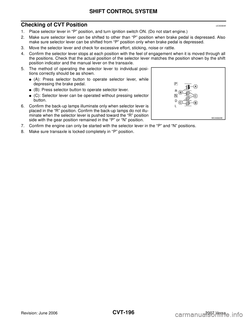
5. The method of operating the selector lever to individual posi-
tions correctly should be as shown.
�(A): Press selector button to operate selector lever, while
depressing the brake pedal.
�(B): Press selector button to operate selector lever.
�(C): Selector lever can be operated without pressing selector
button.
6. Confirm the back-up lamps illuminate only when selector lever is
placed in the “R” position. Confirm the back-up lamps do not illu-
minate when the selector lever is pushed toward the “R” position
side with the gear position remained in the “P” or “N” position.
7. Confirm the engine can only be started with the selector lever in the “P” and “N” positions.
8. Make sure transaxle is locked completely in “P” position.
WCIA0620E
Page 1100 of 2896
KEY INTERLOCK CABLE
CVT-203
D
E
F
G
H
I
J
K
L
MA
B
CVT
Revision: June 20062007 Versa
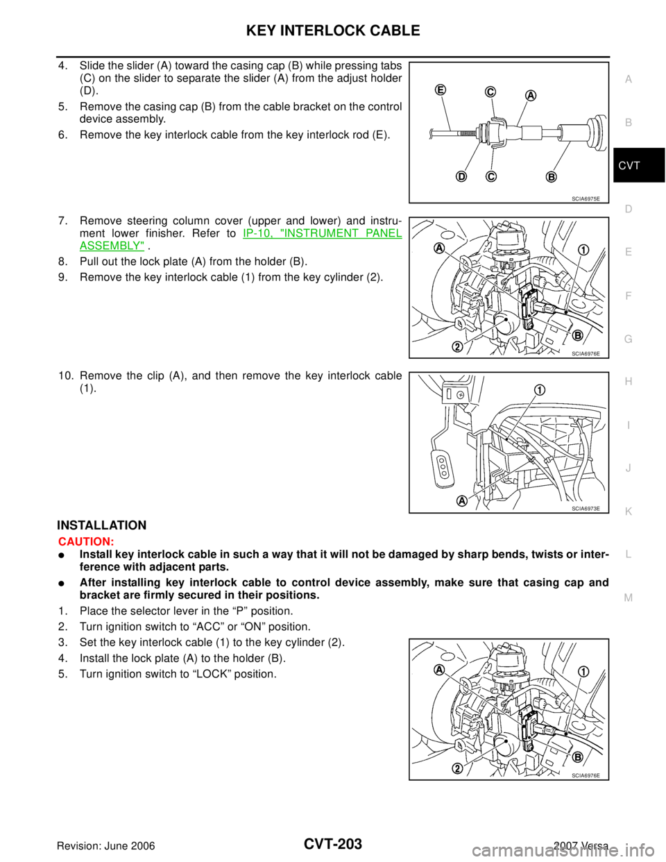
4. Slide the slider (A) toward the casing cap (B) while pressing tabs
(C) on the slider to separate the slider (A) from the adjust holder
(D).
5. Remove the casing cap (B) from the cable bracket on the control
device assembly.
6. Remove the key interlock cable from the key interlock rod (E).
7. Remove steering column cover (upper and lower) and instru-
ment lower finisher. Refer to IP-10, "
INSTRUMENT PANEL
ASSEMBLY" .
8. Pull out the lock plate (A) from the holder (B).
9. Remove the key interlock cable (1) from the key cylinder (2).
10. Remove the clip (A), and then remove the key interlock cable
(1).
INSTALLATION
CAUTION:
�Install key interlock cable in such a way that it will not be damaged by sharp bends, twists or inter-
ference with adjacent parts.
�After installing key interlock cable to control device assembly, make sure that casing cap and
bracket are firmly secured in their positions.
1. Place the selector lever in the “P” position.
2. Turn ignition switch to “ACC” or “ON” position.
3. Set the key interlock cable (1) to the key cylinder (2).
4. Install the lock plate (A) to the holder (B).
5. Turn ignition switch to “LOCK” position.
SCIA6975E
SCIA6976E
SCIA6973E
SCIA6976E
Page 1101 of 2896
CVT-204
KEY INTERLOCK CABLE
Revision: June 20062007 Versa
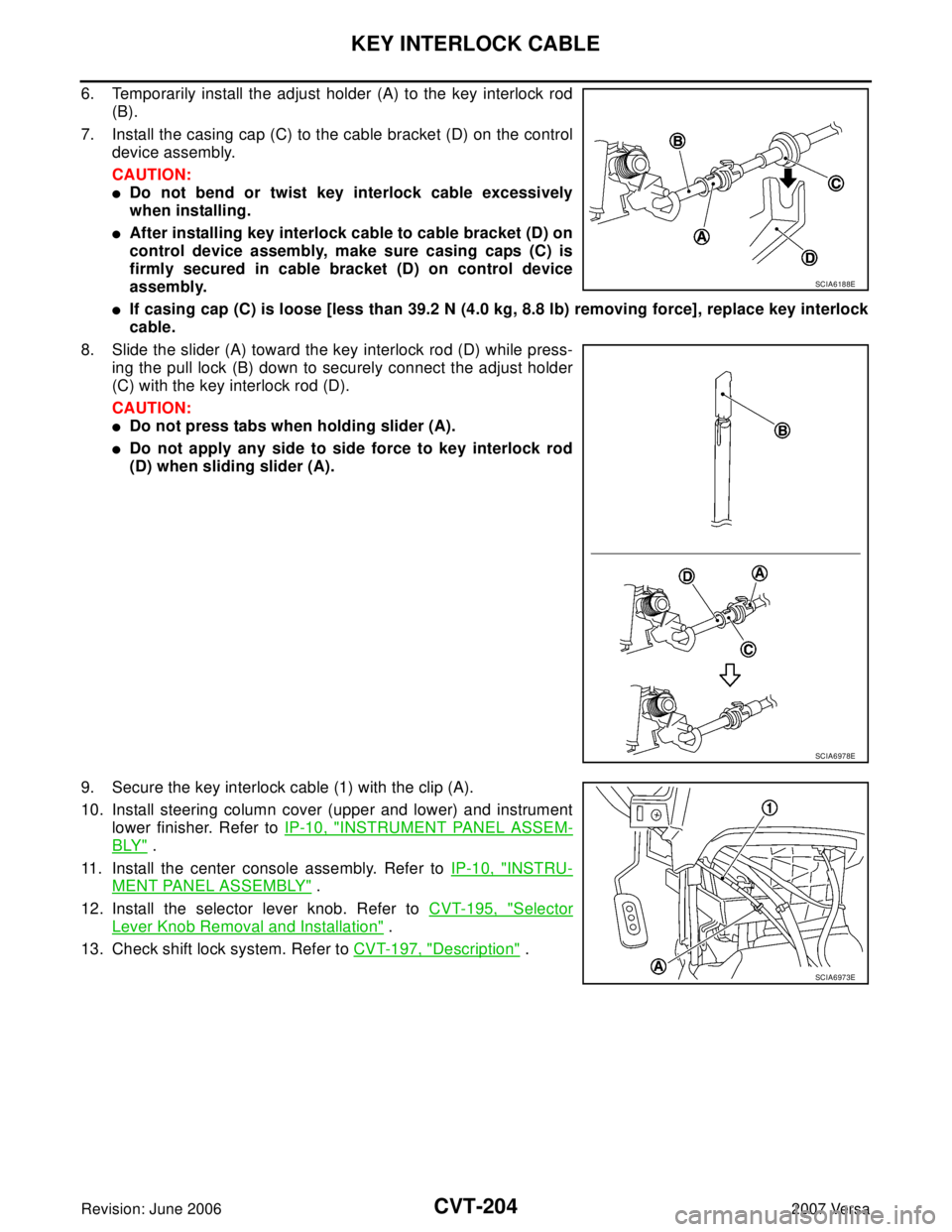
6. Temporarily install the adjust holder (A) to the key interlock rod
(B).
7. Install the casing cap (C) to the cable bracket (D) on the control
device assembly.
CAUTION:
�Do not bend or twist key interlock cable excessively
when installing.
�After installing key interlock cable to cable bracket (D) on
control device assembly, make sure casing caps (C) is
firmly secured in cable bracket (D) on control device
assembly.
�If casing cap (C) is loose [less than 39.2 N (4.0 kg, 8.8 lb) removing force], replace key interlock
cable.
8. Slide the slider (A) toward the key interlock rod (D) while press-
ing the pull lock (B) down to securely connect the adjust holder
(C) with the key interlock rod (D).
CAUTION:
�Do not press tabs when holding slider (A).
�Do not apply any side to side force to key interlock rod
(D) when sliding slider (A).
9. Secure the key interlock cable (1) with the clip (A).
10. Install steering column cover (upper and lower) and instrument
lower finisher. Refer to IP-10, "
INSTRUMENT PANEL ASSEM-
BLY" .
11. Install the center console assembly. Refer to IP-10, "
INSTRU-
MENT PANEL ASSEMBLY" .
12. Install the selector lever knob. Refer to CVT-195, "
Selector
Lever Knob Removal and Installation" .
13. Check shift lock system. Refer to CVT-197, "
Description" .
SCIA6188E
SCIA6978E
SCIA6973E
Page 1131 of 2896
DI-22
COMBINATION METERS
Revision: June 20062007 Versa
Fuel Gauge Fluctuates, Indicates Wrong Value, or VariesEKS00I0K
1. CHECK FUEL GAUGE FLUCTUATION
Test drive vehicle to see if gauge fluctuates only during driving or at the instant of stopping.
Does the indication value vary only during driving or at the at the instant of stopping?
YES >> The pointer fluctuation may be caused by fuel level change in the fuel tank. Condition is normal.
NO >> Ask the customer about the situation when the symptom occurs in detail, and perform the trouble
diagnosis.
Fuel Gauge Does Not Move to Full positionEKS00I0L
1. OBSERVE FUEL GAUGE
Does it take a long time for the pointer to move to FULL position?
YES or NO
YES >> GO TO 2.
NO >> GO TO 3.
2. IDENTIFY FUELING CONDITION
Was the vehicle fueled with the ignition switch ON?
YES or NO
YES >> Be sure to fuel the vehicle with the ignition switch OFF. Otherwise, it will take a long time to move
to FULL position because of the characteristic of the fuel gauge.
NO >> GO TO 3.
3. OBSERVE VEHICLE POSITION
Is the vehicle parked on an incline?
YES or NO
YES >> Check the fuel level indication with vehicle on a level surface.
NO >> GO TO 4.
4. OBSERVE FUEL GAUGE POINTER
During driving, does the fuel gauge pointer move gradually toward EMPTY position?
YES or NO
YES >> Check the components. Refer to DI-23, "FUEL LEVEL SENSOR UNIT CHECK" .
NO >> The float arm may interfere or bind with any of the components in the fuel tank.
DTC [U1000] CAN Communication CircuitEKS00IAR
Symptom: Display CAN COMM CIRC [U1000] at the result of self-diagnosis for combination meter.
1. CHECK CAN COMMUNICATION
1. Select "SELF-DIAG RESULTS" mode for "METER" with CONSULT-II.
2. Print out CONSULT-II screen.
>> Go to "CAN SYSTEM". Refer to LAN-44, "
TROUBLE DIAGNOSIS" .
Page 1853 of 2896
EM-44Revision: June 2006
TIMING CHAIN
2007 Versa
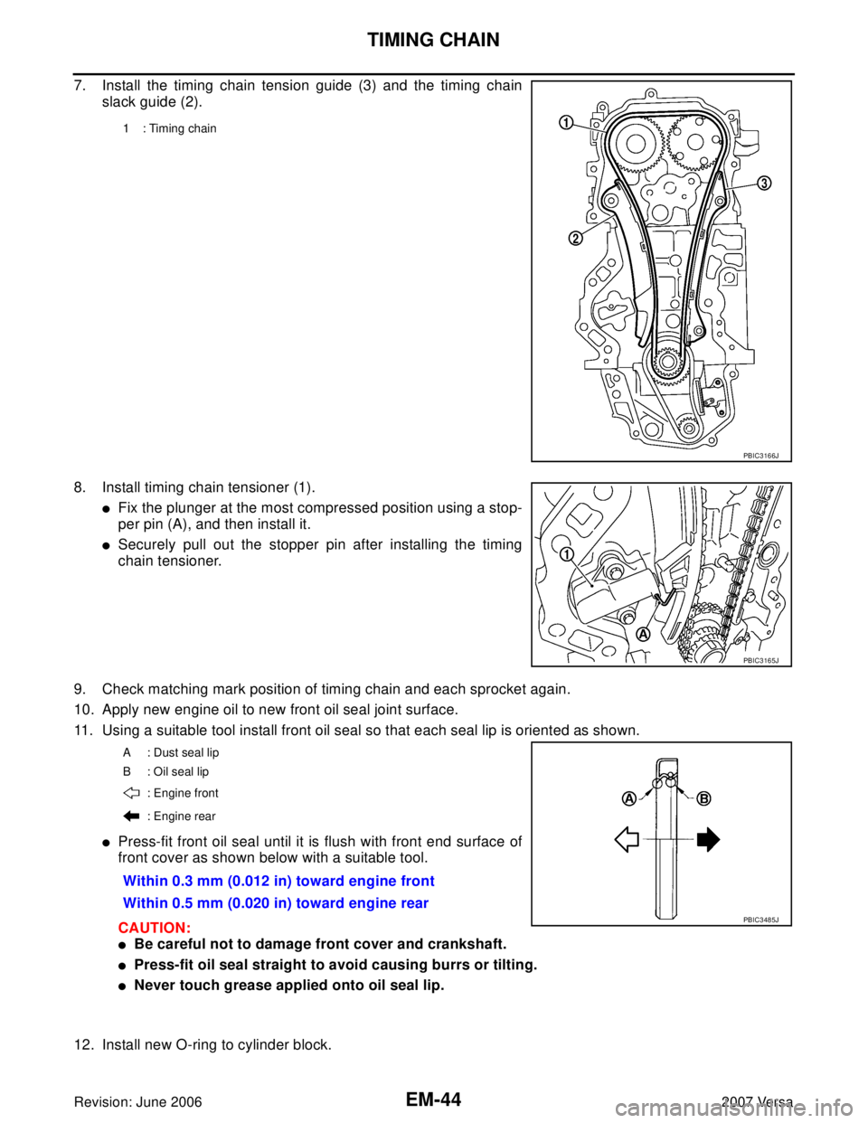
7. Install the timing chain tension guide (3) and the timing chain
slack guide (2).
8. Install timing chain tensioner (1).
�Fix the plunger at the most compressed position using a stop-
per pin (A), and then install it.
�Securely pull out the stopper pin after installing the timing
chain tensioner.
9. Check matching mark position of timing chain and each sprocket again.
10. Apply new engine oil to new front oil seal joint surface.
11. Using a suitable tool install front oil seal so that each seal lip is oriented as shown.
�Press-fit front oil seal until it is flush with front end surface of
front cover as shown below with a suitable tool.
CAUTION:
�Be careful not to damage front cover and crankshaft.
�Press-fit oil seal straight to avoid causing burrs or tilting.
�Never touch grease applied onto oil seal lip.
12. Install new O-ring to cylinder block.
1 : Timing chain
PBIC3166J
PBIC3165J
A : Dust seal lip
B: Oil seal lip
: Engine front
: Engine rear
Within 0.3 mm (0.012 in) toward engine front
Within 0.5 mm (0.020 in) toward engine rear
PBIC3485J
Page 1869 of 2896
EM-60Revision: June 2006
OIL SEAL
2007 Versa
Removal and Installation of Front Oil SealEBS00T6I
REMOVAL
1. Remove the following parts.
�Front fender protector (RH); Refer to EI-22, "FENDER PROTECTOR" .
�Drive belt; Refer to EM-13, "Components" .
�Crankshaft pulley; Refer to EM-37, "Components" .
2. Remove front oil seal using a suitable tool.
CAUTION:
Be careful not to damage front cover and crankshaft.
INSTALLATION
1. Apply new engine oil to new front oil seal joint surface and seal lip.
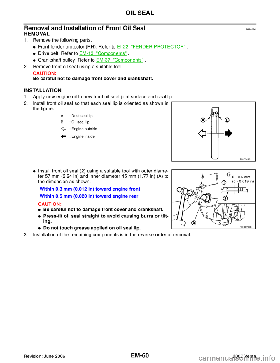
2. Install front oil seal so that each seal lip is oriented as shown in
the figure.
�Install front oil seal (2) using a suitable tool with outer diame-
ter 57 mm (2.24 in) and inner diameter 45 mm (1.77 in) (A) to
the dimension as shown.
CAUTION:
�Be careful not to damage front cover and crankshaft.
�Press-fit oil seal straight to avoid causing burrs or tilt-
ing.
�Do not touch grease applied on oil seal lip.
3. Installation of the remaining components is in the reverse order of removal.
A : Dust seal lip
B: Oil seal lip
: Engine outside
: Engine inside
PBIC3485J
Within 0.3 mm (0.012 in) toward engine front
Within 0.5 mm (0.020 in) toward engine rear
PBIC3729E
Page 1891 of 2896
EM-82Revision: June 2006
CYLINDER BLOCK
2007 Versa
5. Install the main bearings paying attention to the direction.
CAUTION:
�Before installing main bearings, apply new engine oil to the bearing surface (inside). Do not
apply new engine oil to the back surface, but thoroughly clean it.
�When installing, align main bearing to the center position of cylinder block and main bearing
cap.
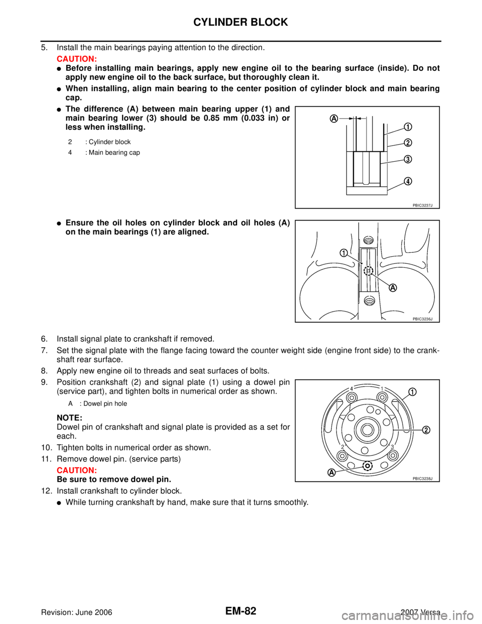
�The difference (A) between main bearing upper (1) and
main bearing lower (3) should be 0.85 mm (0.033 in) or
less when installing.
�Ensure the oil holes on cylinder block and oil holes (A)
on the main bearings (1) are aligned.
6. Install signal plate to crankshaft if removed.
7. Set the signal plate with the flange facing toward the counter weight side (engine front side) to the crank-
shaft rear surface.
8. Apply new engine oil to threads and seat surfaces of bolts.
9. Position crankshaft (2) and signal plate (1) using a dowel pin
(service part), and tighten bolts in numerical order as shown.
NOTE:
Dowel pin of crankshaft and signal plate is provided as a set for
each.
10. Tighten bolts in numerical order as shown.
11. Remove dowel pin. (service parts)
CAUTION:
Be sure to remove dowel pin.
12. Install crankshaft to cylinder block.
�While turning crankshaft by hand, make sure that it turns smoothly.
2 : Cylinder block
4 : Main bearing cap
PBIC3237J
PBIC3236J
A : Dowel pin hole
PBIC3238J