Page 1203 of 2896
EC-34Revision: June 2006
EVAPORATIVE EMISSION SYSTEM
2007 Versa
Component InspectionUBS00QB9
EVAP CANISTER
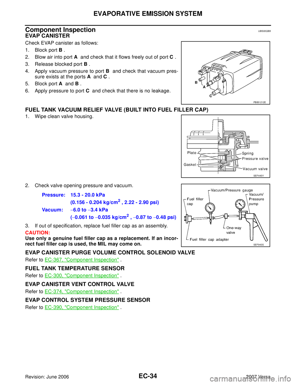
Check EVAP canister as follows:
1. Block port B .
2. Blow air into port A and check that it flows freely out of port C .
3. Release blocked port B .
4. Apply vacuum pressure to port B and check that vacuum pres-
sure exists at the ports A and C .
5. Block port A and B .
6. Apply pressure to port C and check that there is no leakage.
FUEL TANK VACUUM RELIEF VALVE (BUILT INTO FUEL FILLER CAP)
1. Wipe clean valve housing.
2. Check valve opening pressure and vacuum.
3. If out of specification, replace fuel filler cap as an assembly.
CAUTION:
Use only a genuine fuel filler cap as a replacement. If an incor-
rect fuel filler cap is used, the MIL may come on.
EVAP CANISTER PURGE VOLUME CONTROL SOLENOID VALVE
Refer to EC-367, "Component Inspection" .
FUEL TANK TEMPERATURE SENSOR
Refer to EC-300, "Component Inspection" .
EVAP CANISTER VENT CONTROL VALVE
Refer to EC-374, "Component Inspection" .
EVAP CONTROL SYSTEM PRESSURE SENSOR
Refer to EC-390, "Component Inspection" .
PBIB1212E
SEF 4 45 Y
Pressure: 15.3 - 20.0 kPa
(0.156 - 0.204 kg/cm
2 , 2.22 - 2.90 psi)
Vac uu m :−6.0 to −3.4 kPa
(−0.061 to −0.035 kg/cm
2 , −0.87 to −0.48 psi)
SEF 9 43 S
Page 1204 of 2896
EVAPORATIVE EMISSION SYSTEM
EC-35
C
D
E
F
G
H
I
J
K
L
MA
EC
Revision: June 20062007 Versa
EVAP SERVICE PORT
Positive pressure is delivered to the EVAP system through the EVAP
service port. If fuel vapor leakage in the EVAP system occurs, use a
leak detector to locate the leak.
Removal and InstallationUBS00QBA
EVAP CANISTER
Tighten EVAP canister as shown in the figure.
EVAP CANISTER VENT CONTROL VALVE
1. Turn EVAP canister vent control valve counterclockwise.
�Lock (A)
�Unlock (B)
2. Remove the EVAP canister vent control valve.
Always replace O-ring with a new one.
How to Detect Fuel Vapor LeakageUBS00QBB
CAUTION:
�Never use compressed air or a high pressure pump.
�Do not exceed 4.12 kPa (0.042 kg/cm2 , 0.6 psi) of pressure in EVAP system.
NOTE:
�Do not start engine.
�Improper installation of EVAP service port adapter to the EVAP service port may cause a leak.
SEF 4 62 UC
PBIB1214E
PBIB3091E
Page 1207 of 2896
EC-38Revision: June 2006
ON BOARD REFUELING VAPOR RECOVERY (ORVR)
2007 Versa
ON BOARD REFUELING VAPOR RECOVERY (ORVR)PFP:00032
System DescriptionUBS00QBC
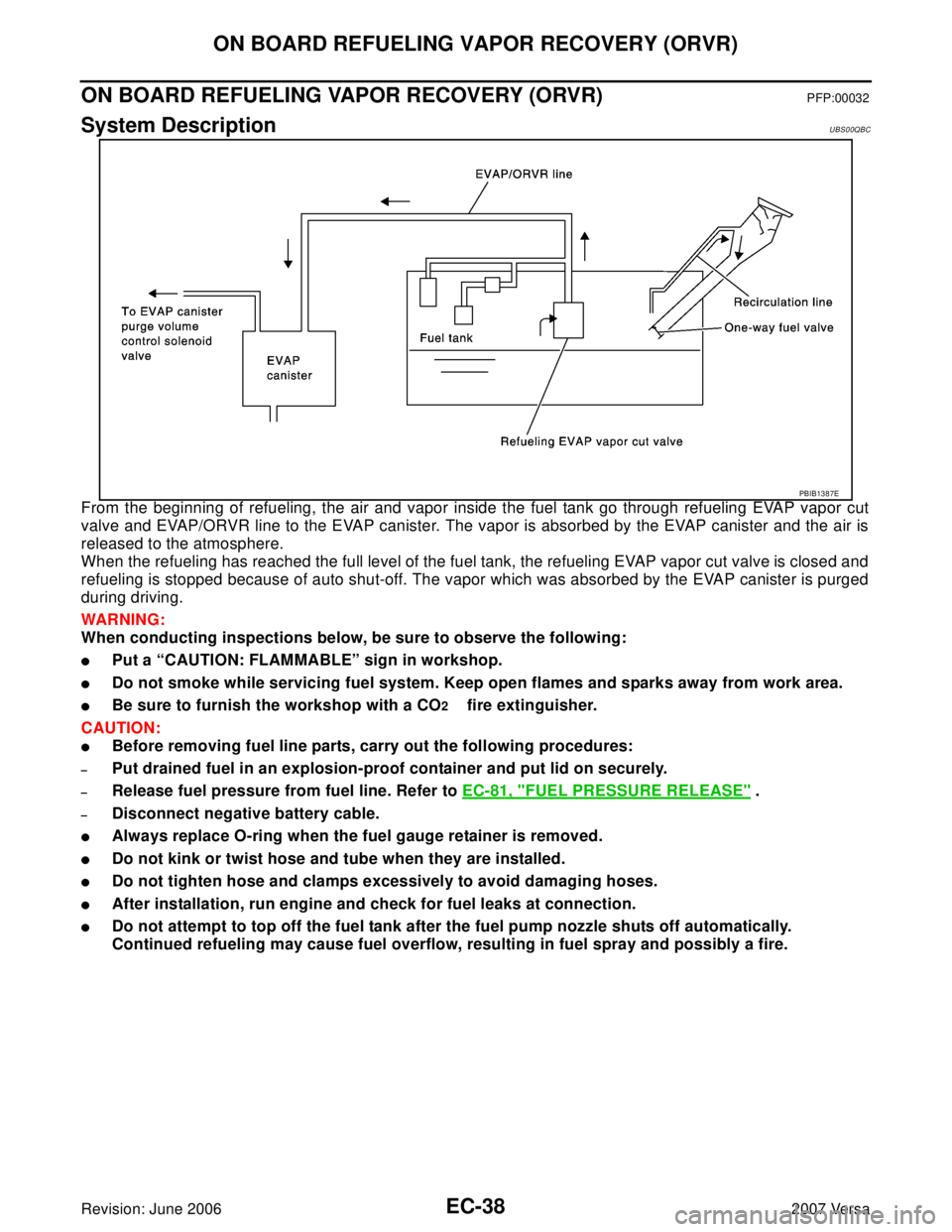
From the beginning of refueling, the air and vapor inside the fuel tank go through refueling EVAP vapor cut
valve and EVAP/ORVR line to the EVAP canister. The vapor is absorbed by the EVAP canister and the air is
released to the atmosphere.
When the refueling has reached the full level of the fuel tank, the refueling EVAP vapor cut valve is closed and
refueling is stopped because of auto shut-off. The vapor which was absorbed by the EVAP canister is purged
during driving.
WAR NIN G:
When conducting inspections below, be sure to observe the following:
�Put a “CAUTION: FLAMMABLE” sign in workshop.
�Do not smoke while servicing fuel system. Keep open flames and sparks away from work area.
�Be sure to furnish the workshop with a CO2 fire extinguisher.
CAUTION:
�Before removing fuel line parts, carry out the following procedures:
–Put drained fuel in an explosion-proof container and put lid on securely.
–Release fuel pressure from fuel line. Refer to EC-81, "FUEL PRESSURE RELEASE" .
–Disconnect negative battery cable.
�Always replace O-ring when the fuel gauge retainer is removed.
�Do not kink or twist hose and tube when they are installed.
�Do not tighten hose and clamps excessively to avoid damaging hoses.
�After installation, run engine and check for fuel leaks at connection.
�Do not attempt to top off the fuel tank after the fuel pump nozzle shuts off automatically.
Continued refueling may cause fuel overflow, resulting in fuel spray and possibly a fire.
PBIB1387E
Page 1208 of 2896
ON BOARD REFUELING VAPOR RECOVERY (ORVR)
EC-39
C
D
E
F
G
H
I
J
K
L
MA
EC
Revision: June 20062007 Versa
Diagnostic ProcedureUBS00QBD
SYMPTOM: FUEL ODOR FROM EVAP CANISTER IS STRONG.
1. CHECK EVAP CANISTER
1. Remove EVAP canister with EVAP canister vent control valve and EVAP control system pressure sensor
attached.
2. Weigh the EVAP canister with EVAP canister vent control valve and EVAP control system pressure sensor
attached.
The weight should be less than 1.9 kg (4.2 lb).
OK or NG
OK >> GO TO 2.
NG >> GO TO 3.
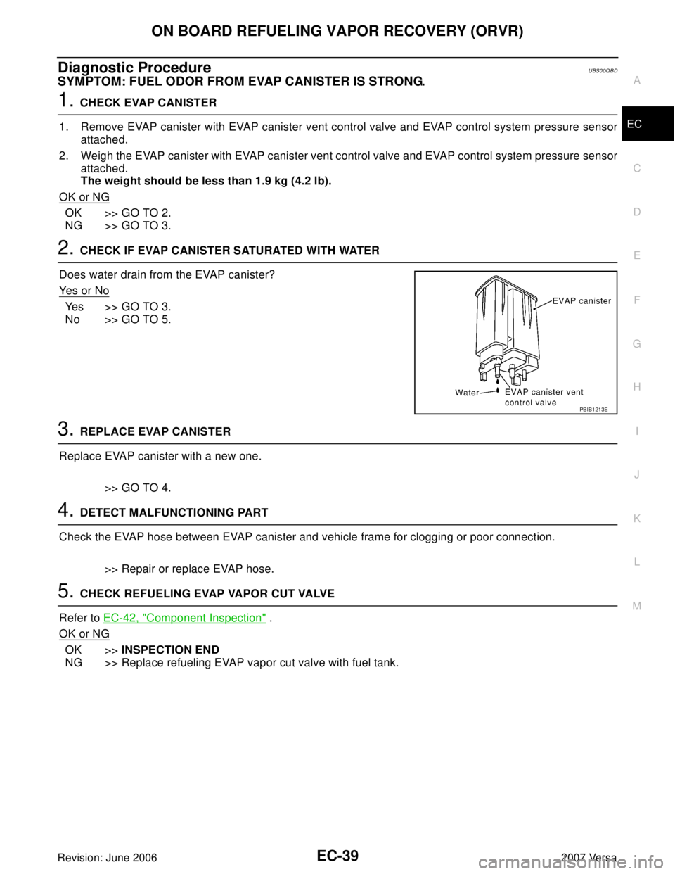
2. CHECK IF EVAP CANISTER SATURATED WITH WATER
Does water drain from the EVAP canister?
Ye s o r N o
Yes >> GO TO 3.
No >> GO TO 5.
3. REPLACE EVAP CANISTER
Replace EVAP canister with a new one.
>> GO TO 4.
4. DETECT MALFUNCTIONING PART
Check the EVAP hose between EVAP canister and vehicle frame for clogging or poor connection.
>> Repair or replace EVAP hose.
5. CHECK REFUELING EVAP VAPOR CUT VALVE
Refer to EC-42, "
Component Inspection" .
OK or NG
OK >>INSPECTION END
NG >> Replace refueling EVAP vapor cut valve with fuel tank.
PBIB1213E
Page 1209 of 2896
EC-40Revision: June 2006
ON BOARD REFUELING VAPOR RECOVERY (ORVR)
2007 Versa
SYMPTOM: CANNOT REFUEL/FUEL ODOR FROM THE FUEL FILLER OPENING IS STRONG
WHILE REFUELING.
1. CHECK EVAP CANISTER
1. Remove EVAP canister with EVAP canister vent control valve and EVAP control system pressure sensor
attached.
2. Weigh the EVAP canister with EVAP canister vent control valve and EVAP control system pressure sensor
attached.
The weight should be less than 1.9 kg (4.2 lb).
OK or NG
OK >> GO TO 2.
NG >> GO TO 3.
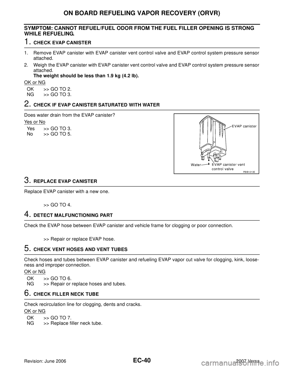
2. CHECK IF EVAP CANISTER SATURATED WITH WATER
Does water drain from the EVAP canister?
Ye s o r N o
Yes >> GO TO 3.
No >> GO TO 5.
3. REPLACE EVAP CANISTER
Replace EVAP canister with a new one.
>> GO TO 4.
4. DETECT MALFUNCTIONING PART
Check the EVAP hose between EVAP canister and vehicle frame for clogging or poor connection.
>> Repair or replace EVAP hose.
5. CHECK VENT HOSES AND VENT TUBES
Check hoses and tubes between EVAP canister and refueling EVAP vapor cut valve for clogging, kink, loose-
ness and improper connection.
OK or NG
OK >> GO TO 6.
NG >> Repair or replace hoses and tubes.
6. CHECK FILLER NECK TUBE
Check recirculation line for clogging, dents and cracks.
OK or NG
OK >> GO TO 7.
NG >> Replace filler neck tube.
PBIB1213E
Page 1211 of 2896
EC-42Revision: June 2006
ON BOARD REFUELING VAPOR RECOVERY (ORVR)
2007 Versa
Component InspectionUBS00QBE
REFUELING EVAP VAPOR CUT VALVE
With CONSULT-II
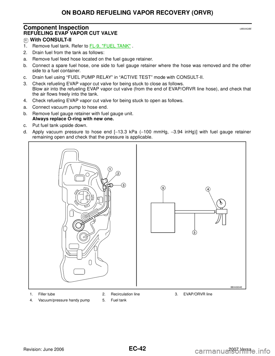
1. Remove fuel tank. Refer to FL-9, "FUEL TANK" .
2. Drain fuel from the tank as follows:
a. Remove fuel feed hose located on the fuel gauge retainer.
b. Connect a spare fuel hose, one side to fuel gauge retainer where the hose was removed and the other
side to a fuel container.
c. Drain fuel using “FUEL PUMP RELAY” in “ACTIVE TEST” mode with CONSULT-II.
3. Check refueling EVAP vapor cut valve for being stuck to close as follows.
Blow air into the refueling EVAP vapor cut valve (from the end of EVAP/ORVR line hose), and check that
the air flows freely into the tank.
4. Check refueling EVAP vapor cut valve for being stuck to open as follows.
a. Connect vacuum pump to hose end.
b. Remove fuel gauge retainer with fuel gauge unit.
Always replace O-ring with new one.
c. Put fuel tank upside down.
d. Apply vacuum pressure to hose end [−13.3 kPa (−100 mmHg, −3.94 inHg)] with fuel gauge retainer
remaining open and check that the pressure is applicable.
1. Filler tube 2. Recirculation line 3. EVAP/ORVR line
4. Vacuum/pressure handy pump 5. Fuel tank
BBIA0694E
Page 1212 of 2896
ON BOARD REFUELING VAPOR RECOVERY (ORVR)
EC-43
C
D
E
F
G
H
I
J
K
L
MA
EC
Revision: June 20062007 Versa
Without CONSULT-II
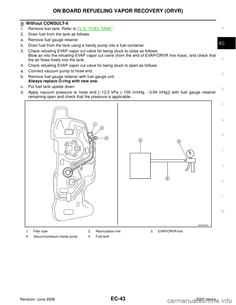
1. Remove fuel tank. Refer to FL-9, "FUEL TANK" .
2. Drain fuel from the tank as follows:
a. Remove fuel gauge retainer.
b. Drain fuel from the tank using a handy pump into a fuel container.
3. Check refueling EVAP vapor cut valve for being stuck to close as follows.
Blow air into the refueling EVAP vapor cut valve (from the end of EVAP/ORVR line hose), and check that
the air flows freely into the tank.
4. Check refueling EVAP vapor cut valve for being stuck to open as follows.
a. Connect vacuum pump to hose end.
b. Remove fuel gauge retainer with fuel gauge unit.
Always replace O-ring with new one.
c. Put fuel tank upside down.
d. Apply vacuum pressure to hose end [−13.3 kPa (−100 mmHg, −3.94 inHg)] with fuel gauge retainer
remaining open and check that the pressure is applicable.
1. Filler tube 2. Recirculation line 3. EVAP/ORVR line
4. Vacuum/pressure handy pump 5. Fuel tank
BBIA0694E
Page 1250 of 2896
BASIC SERVICE PROCEDURE
EC-81
C
D
E
F
G
H
I
J
K
L
MA
EC
Revision: June 20062007 Versa
Fuel Pressure CheckUBS00QOB
FUEL PRESSURE RELEASE
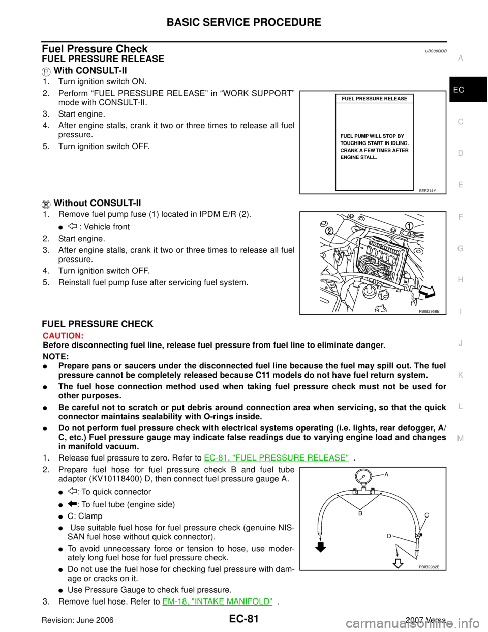
With CONSULT-II
1. Turn ignition switch ON.
2. Perform “FUEL PRESSURE RELEASE” in “WORK SUPPORT”
mode with CONSULT-II.
3. Start engine.
4. After engine stalls, crank it two or three times to release all fuel
pressure.
5. Turn ignition switch OFF.
Without CONSULT-II
1. Remove fuel pump fuse (1) located in IPDM E/R (2).
� : Vehicle front
2. Start engine.
3. After engine stalls, crank it two or three times to release all fuel
pressure.
4. Turn ignition switch OFF.
5. Reinstall fuel pump fuse after servicing fuel system.
FUEL PRESSURE CHECK
CAUTION:
Before disconnecting fuel line, release fuel pressure from fuel line to eliminate danger.
NOTE:
�Prepare pans or saucers under the disconnected fuel line because the fuel may spill out. The fuel
pressure cannot be completely released because C11 models do not have fuel return system.
�The fuel hose connection method used when taking fuel pressure check must not be used for
other purposes.
�Be careful not to scratch or put debris around connection area when servicing, so that the quick
connector maintains sealability with O-rings inside.
�Do not perform fuel pressure check with electrical systems operating (i.e. lights, rear defogger, A/
C, etc.) Fuel pressure gauge may indicate false readings due to varying engine load and changes
in manifold vacuum.
1. Release fuel pressure to zero. Refer to EC-81, "
FUEL PRESSURE RELEASE" .
2. Prepare fuel hose for fuel pressure check B and fuel tube
adapter (KV10118400) D, then connect fuel pressure gauge A.
�: To quick connector
�: To fuel tube (engine side)
�C: Clamp
� Use suitable fuel hose for fuel pressure check (genuine NIS-
SAN fuel hose without quick connector).
�To avoid unnecessary force or tension to hose, use moder-
ately long fuel hose for fuel pressure check.
�Do not use the fuel hose for checking fuel pressure with dam-
age or cracks on it.
�Use Pressure Gauge to check fuel pressure.
3. Remove fuel hose. Refer to EM-18, "
INTAKE MANIFOLD" .
SEF 2 14 Y
PBIB2958E
PBIB2982E