2007 NISSAN LATIO fuel filter
[x] Cancel search: fuel filterPage 1522 of 2896
DTC P0442 EVAP CONTROL SYSTEM
EC-353
C
D
E
F
G
H
I
J
K
L
MA
EC
Revision: June 20062007 Versa
22. CHECK REFUELING EVAP VAPOR CUT VALVE
Refer to EC-42, "
Component Inspection" .
OK or NG
OK >> GO TO 23.
NG >> Replace refueling EVAP vapor cut valve with fuel tank.
23. CHECK FUEL LEVEL SENSOR
Refer to FL-5, "
FUEL LEVEL SENSOR UNIT, FUEL FILTER AND FUEL PUMP ASSEMBLY" .
OK or NG
OK >> GO TO 24.
NG >> Replace fuel level sensor unit.
24. CHECK INTERMITTENT INCIDENT
Refer to EC-143, "
TROUBLE DIAGNOSIS FOR INTERMITTENT INCIDENT" .
>>INSPECTION END
Page 1583 of 2896
EC-414Revision: June 2006
DTC P0456 EVAP CONTROL SYSTEM
2007 Versa
20. CHECK EVAP/ORVR LINE
Check EVAP/ORVR line between EVAP canister and fuel tank for clogging, kink, looseness and improper con-
nection. For location, refer to EC-38, "
ON BOARD REFUELING VAPOR RECOVERY (ORVR)" .
OK or NG
OK >> GO TO 21.
NG >> Repair or replace hoses and tubes.
21. CHECK RECIRCULATION LINE
Check recirculation line between filler neck tube and fuel tank for clogging, kink, cracks, looseness and
improper connection.
OK or NG
OK >> GO TO 22.
NG >> Repair or replace hose, tube or filler neck tube.
22. CHECK REFUELING EVAP VAPOR CUT VALVE
Refer to EC-42, "
Component Inspection" .
OK or NG
OK >> GO TO 23.
NG >> Replace refueling EVAP vapor cut valve with fuel tank.
23. CHECK FUEL LEVEL SENSOR
Refer to FL-5, "
FUEL LEVEL SENSOR UNIT, FUEL FILTER AND FUEL PUMP ASSEMBLY" .
OK or NG
OK >> GO TO 24.
NG >> Replace fuel level sensor unit.
24. CHECK INTERMITTENT INCIDENT
Refer to EC-143, "
TROUBLE DIAGNOSIS FOR INTERMITTENT INCIDENT" .
>>INSPECTION END
Page 1585 of 2896
EC-416Revision: June 2006
DTC P0460 FUEL LEVEL SENSOR
2007 Versa
Diagnostic ProcedureUBS00QJO
1. CHECK FUEL GAUGE OPERATION
Refer to DI-13, "
Self-Diagnosis Mode of Combination Meter" .
OK or NG
OK >> GO TO 2.
NG >> Follow the instruction of DI-13, "
Self-Diagnosis Mode of Combination Meter" .
2. CHECK FUEL LEVEL SENSOR AND CIRCUIT
Refer to DI-20, "
Fuel Level Sensor Signal Inspection" .
OK or NG
OK >> GO TO 3.
NG >> Repair or replace malfunctioning parts.
3. CHECK INTERMITTENT INCIDENT
Refer to EC-143, "
TROUBLE DIAGNOSIS FOR INTERMITTENT INCIDENT" .
>>INSPECTION END
Removal and InstallationUBS00QJP
FUEL LEVEL SENSOR
Refer to FL-5, "FUEL LEVEL SENSOR UNIT, FUEL FILTER AND FUEL PUMP ASSEMBLY"
Page 1587 of 2896
EC-418Revision: June 2006
DTC P0461 FUEL LEVEL SENSOR
2007 Versa
5. Turn ignition switch OFF and wait at least 10 seconds then turn
ON.
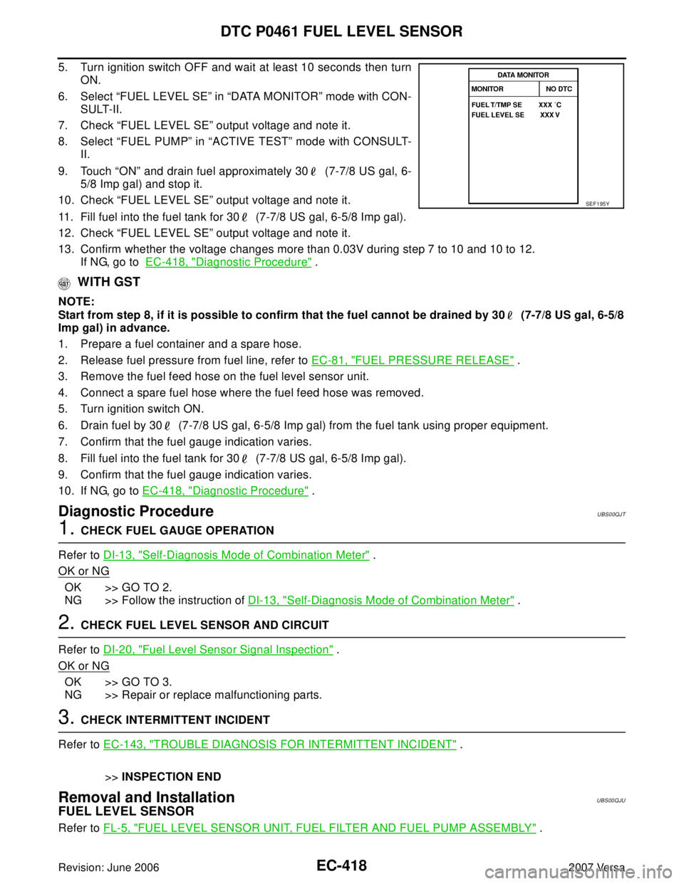
6. Select “FUEL LEVEL SE” in “DATA MONITOR” mode with CON-
SULT-II.
7. Check “FUEL LEVEL SE” output voltage and note it.
8. Select “FUEL PUMP” in “ACTIVE TEST” mode with CONSULT-
II.
9. Touch “ON” and drain fuel approximately 30 (7-7/8 US gal, 6-
5/8 Imp gal) and stop it.
10. Check “FUEL LEVEL SE” output voltage and note it.
11. Fill fuel into the fuel tank for 30 (7-7/8 US gal, 6-5/8 Imp gal).
12. Check “FUEL LEVEL SE” output voltage and note it.
13. Confirm whether the voltage changes more than 0.03V during step 7 to 10 and 10 to 12.
If NG, go to EC-418, "
Diagnostic Procedure" .
WITH GST
NOTE:
Start from step 8, if it is possible to confirm that the fuel cannot be drained by 30 (7-7/8 US gal, 6-5/8
Imp gal) in advance.
1. Prepare a fuel container and a spare hose.
2. Release fuel pressure from fuel line, refer to EC-81, "
FUEL PRESSURE RELEASE" .
3. Remove the fuel feed hose on the fuel level sensor unit.
4. Connect a spare fuel hose where the fuel feed hose was removed.
5. Turn ignition switch ON.
6. Drain fuel by 30 (7-7/8 US gal, 6-5/8 Imp gal) from the fuel tank using proper equipment.
7. Confirm that the fuel gauge indication varies.
8. Fill fuel into the fuel tank for 30 (7-7/8 US gal, 6-5/8 Imp gal).
9. Confirm that the fuel gauge indication varies.
10. If NG, go to EC-418, "
Diagnostic Procedure" .
Diagnostic ProcedureUBS00QJT
1. CHECK FUEL GAUGE OPERATION
Refer to DI-13, "
Self-Diagnosis Mode of Combination Meter" .
OK or NG
OK >> GO TO 2.
NG >> Follow the instruction of DI-13, "
Self-Diagnosis Mode of Combination Meter" .
2. CHECK FUEL LEVEL SENSOR AND CIRCUIT
Refer to DI-20, "
Fuel Level Sensor Signal Inspection" .
OK or NG
OK >> GO TO 3.
NG >> Repair or replace malfunctioning parts.
3. CHECK INTERMITTENT INCIDENT
Refer to EC-143, "
TROUBLE DIAGNOSIS FOR INTERMITTENT INCIDENT" .
>>INSPECTION END
Removal and InstallationUBS00QJU
FUEL LEVEL SENSOR
Refer to FL-5, "FUEL LEVEL SENSOR UNIT, FUEL FILTER AND FUEL PUMP ASSEMBLY" .
SEF 1 95 Y
Page 1589 of 2896
EC-420Revision: June 2006
DTC P0462, P0463 FUEL LEVEL SENSOR
2007 Versa
Diagnostic ProcedureUBS00QJY
1. CHECK FUEL GAUGE OPERATION
Refer to DI-13, "
Self-Diagnosis Mode of Combination Meter" .
OK or NG
OK >> GO TO 2.
NG >> Follow the instruction of DI-13, "
Self-Diagnosis Mode of Combination Meter" .
2. CHECK FUEL LEVEL SENSOR AND CIRCUIT
Refer to DI-20, "
Fuel Level Sensor Signal Inspection" .
OK or NG
OK >> GO TO 3.
NG >> Repair or replace malfunctioning parts.
3. CHECK INTERMITTENT INCIDENT
Refer to EC-143, "
TROUBLE DIAGNOSIS FOR INTERMITTENT INCIDENT" .
>>INSPECTION END
Removal and InstallationUBS00QJZ
FUEL LEVEL SENSOR
Refer to FL-5, "FUEL LEVEL SENSOR UNIT, FUEL FILTER AND FUEL PUMP ASSEMBLY" .
Page 1744 of 2896
FUEL PUMP
EC-575
C
D
E
F
G
H
I
J
K
L
MA
EC
Revision: June 20062007 Versa
Component InspectionUBS00PTY
FUEL PUMP
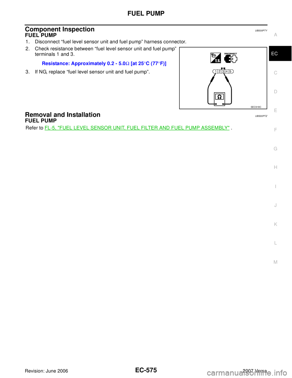
1. Disconnect “fuel level sensor unit and fuel pump” harness connector.
2. Check resistance between “fuel level sensor unit and fuel pump”
terminals 1 and 3.
3. If NG, replace “fuel level sensor unit and fuel pump”.
Removal and InstallationUBS00PTZ
FUEL PUMP
Refer to FL-5, "FUEL LEVEL SENSOR UNIT, FUEL FILTER AND FUEL PUMP ASSEMBLY" . Resistance: Approximately 0.2 - 5.0Ω [at 25°C (77°F)]
SEC9 18 C
Page 1810 of 2896
EM-1
ENGINE MECHANICAL
B ENGINE
CONTENTS
C
D
E
F
G
H
I
J
K
L
M
SECTION EM
A
EM
Revision: June 20062007 Versa PRECAUTIONS .......................................................... 3
Precautions for Supplemental Restraint System
(SRS) “AIR BAG” and “SEAT BELT PRE-TEN-
SIONER” .................................................................. 3
Precautions for Procedures without Cowl Top Cover ..... 3
Precautions Necessary for Steering Wheel Rotation
After Battery Disconnect .......................................... 3
OPERATION PROCEDURE ................................. 3
Precautions for Drain Coolant .................................. 4
Precautions for Disconnecting Fuel Piping .............. 4
Precautions for Removal and Disassembly ............. 4
Precautions for Inspection, Repair and Replace-
ment ......................................................................... 4
Precautions for Assembly and Installation ............... 4
Parts Requiring Angular Tightening ......................... 4
Precautions for Liquid Gasket .................................. 5
REMOVAL OF LIQUID GASKET SEALING .......... 5
LIQUID GASKET APPLICATION PROCEDURE ..... 5
PREPARATION ........................................................... 7
Special Service Tools ............................................... 7
Commercial Service Tools ........................................ 9
NOISE, VIBRATION AND HARSHNESS (NVH)
TROUBLESHOOTING ...............................................11
NVH Troubleshooting — Engine Noise ...................11
Use the Chart Below to Help You Find the Cause
of the Symptom. ..................................................... 12
DRIVE BELTS ........................................................... 13
Components ........................................................... 13
Checking Drive Belts .............................................. 13
Tension Adjustment ................................................ 13
Removal and Installation ........................................ 13
REMOVAL ........................................................... 13
INSTALLATION ................................................... 14
Components ........................................................... 14
Removal and Installation of Drive Belt Auto-Ten-
sioner ..................................................................... 14
REMOVAL ........................................................... 14
INSTALLATION ................................................... 15
AIR CLEANER AND AIR DUCT ............................... 16Components ........................................................... 16
Removal and Installation ........................................ 16
REMOVAL ........................................................... 16
INSTALLATION ................................................... 16
Changing Air Cleaner Filter .................................... 17
REMOVAL ........................................................... 17
INSPECTION AFTER REMOVAL ....................... 17
INSTALLATION ................................................... 17
INTAKE MANIFOLD ................................................. 18
Components ........................................................... 18
Removal and Installation ........................................ 18
REMOVAL ........................................................... 18
INSTALLATION ................................................... 19
INSPECTION AFTER INSTALLATION ................ 20
EXHAUST MANIFOLD ............................................. 21
Components ........................................................... 21
Removal and Installation ........................................ 21
REMOVAL ........................................................... 21
INSPECTION AFTER REMOVAL ....................... 22
INSTALLATION ................................................... 22
OIL PAN .................................................................... 24
Components ........................................................... 24
Removal and Installation ........................................ 24
REMOVAL ........................................................... 24
INSPECTION AFTER REMOVAL ....................... 26
INSTALLATION ................................................... 26
IGNITION COIL, SPARK PLUG AND ROCKER
COVER ...................................................................... 30
Components ........................................................... 30
Removal and Installation ........................................ 30
REMOVAL ........................................................... 30
INSPECTION AFTER REMOVAL ....................... 31
INSTALLATION ................................................... 31
FUEL INJECTOR AND FUEL TUBE ........................ 33
Components ........................................................... 33
Removal and Installation ........................................ 33
REMOVAL ........................................................... 33
INSTALLATION ................................................... 35
TIMING CHAIN .......................................................... 37
Page 1817 of 2896
EM-8Revision: June 2006
PREPARATION
2007 Versa
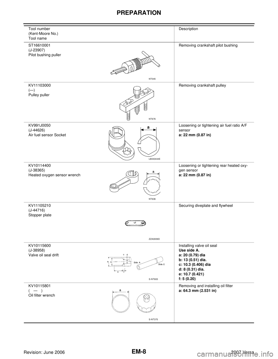
ST16610001
(J-23907)
Pilot bushing pullerRemoving crankshaft pilot bushing
KV11103000
(—)
Pulley pullerRemoving crankshaft pulley
KV991J0050
(J-44626)
Air fuel sensor SocketLoosening or tightening air fuel ratio A/F
sensor
a: 22 mm (0.87 in)
KV10114400
(J-38365)
Heated oxygen sensor wrenchLoosening or tightening rear heated oxy-
gen sensor
a: 22 mm (0.87 in)
KV11105210
(J-44716)
Stopper plateSecuring diveplate and flywheel
KV10115600
(J-38958)
Valve oil seal driftInstalling valve oil seal
Use side A.
a: 20 (0.79) dia
b: 13 (0.51) dia.
c: 10.3 (0.406) dia
d: 8 (0.31) dia.
e: 10.7 (0.421)
f: 5 (0.20)
KV10115801
(—)
Oil filter wrenchRemoving and installing oil filter
a: 64.3 mm (2.531 in) Tool number
(Kent-Moore No.)
Tool nameDescription
NT045
NT676
LBIA0444E
NT636
ZZA0009D
S-NT603
S-NT375