Page 1068 of 2896
OVERDRIVE CONTROL SWITCH
CVT-171
D
E
F
G
H
I
J
K
L
MA
B
CVT
Revision: June 20062007 Versa
Wiring Diagram — CVT — ODSWUCS006KQ
BCWA0686E
Page 1073 of 2896
CVT-176
TROUBLE DIAGNOSIS FOR SYMPTOMS
Revision: June 20062007 Versa
TROUBLE DIAGNOSIS FOR SYMPTOMSPFP:00007
Wiring Diagram — CVT — NONDTCUCS00644
BCWA0682E
Page 1077 of 2896

CVT-180
TROUBLE DIAGNOSIS FOR SYMPTOMS
Revision: June 20062007 Versa
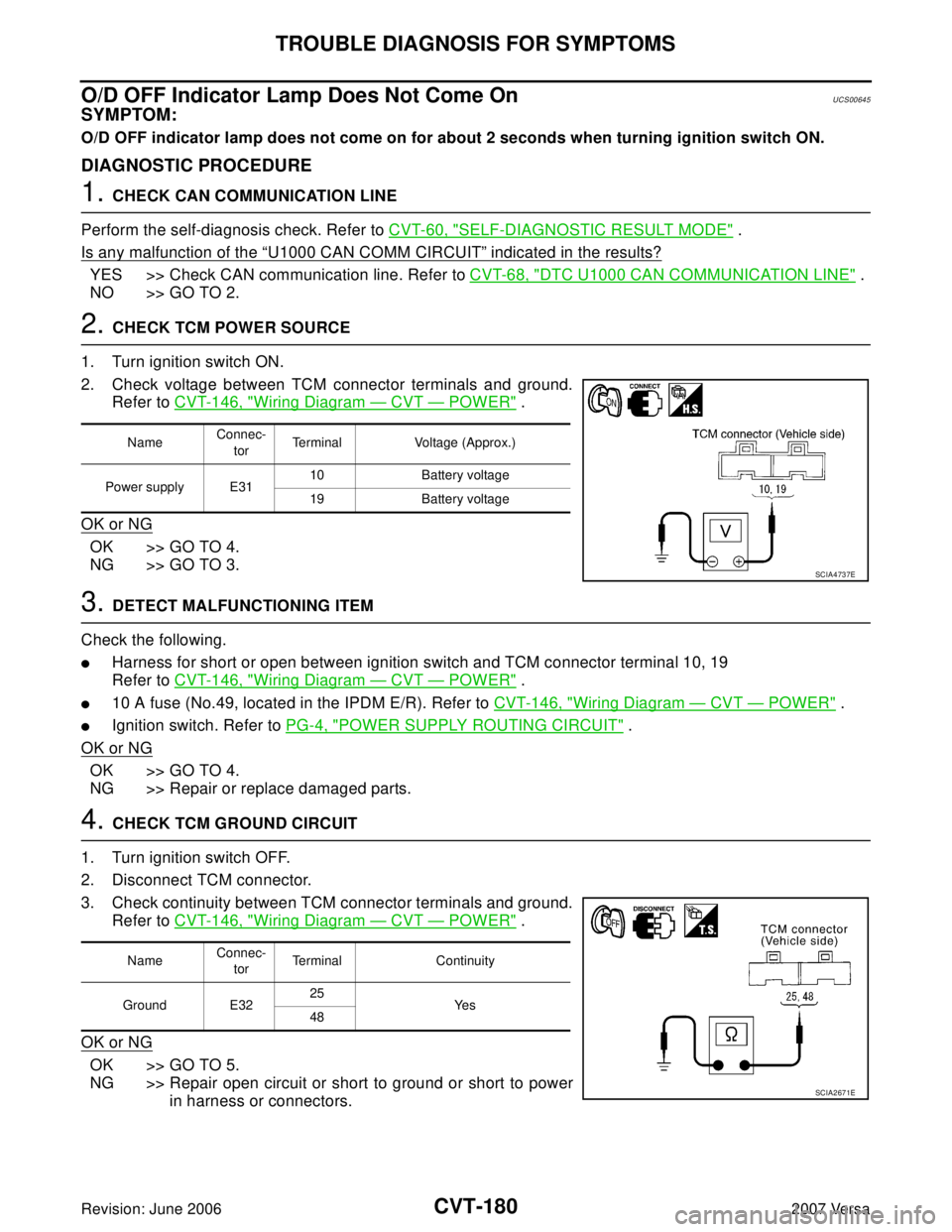
O/D OFF Indicator Lamp Does Not Come OnUCS00645
SYMPTOM:
O/D OFF indicator lamp does not come on for about 2 seconds when turning ignition switch ON.
DIAGNOSTIC PROCEDURE
1. CHECK CAN COMMUNICATION LINE
Perform the self-diagnosis check. Refer to CVT-60, "
SELF-DIAGNOSTIC RESULT MODE" .
Is any malfunction of the
“U1000 CAN COMM CIRCUIT” indicated in the results?
YES >> Check CAN communication line. Refer to CVT-68, "DTC U1000 CAN COMMUNICATION LINE" .
NO >> GO TO 2.
2. CHECK TCM POWER SOURCE
1. Turn ignition switch ON.
2. Check voltage between TCM connector terminals and ground.
Refer to CVT-146, "
Wiring Diagram — CVT — POWER" .
OK or NG
OK >> GO TO 4.
NG >> GO TO 3.
3. DETECT MALFUNCTIONING ITEM
Check the following.
�Harness for short or open between ignition switch and TCM connector terminal 10, 19
Refer to CVT-146, "
Wiring Diagram — CVT — POWER" .
�10 A fuse (No.49, located in the IPDM E/R). Refer to CVT-146, "Wiring Diagram — CVT — POWER" .
�Ignition switch. Refer to PG-4, "POWER SUPPLY ROUTING CIRCUIT" .
OK or NG
OK >> GO TO 4.
NG >> Repair or replace damaged parts.
4. CHECK TCM GROUND CIRCUIT
1. Turn ignition switch OFF.
2. Disconnect TCM connector.
3. Check continuity between TCM connector terminals and ground.
Refer to CVT-146, "
Wiring Diagram — CVT — POWER" .
OK or NG
OK >> GO TO 5.
NG >> Repair open circuit or short to ground or short to power
in harness or connectors.
NameConnec-
torTerminal Voltage (Approx.)
Power supply E3110 Battery voltage
19 Battery voltage
SCIA4737E
NameConnec-
torTerminal Continuity
Ground E3225
Ye s
48
SCIA2671E
Page 1095 of 2896
CVT-198
CVT SHIFT LOCK SYSTEM
Revision: June 20062007 Versa
Wiring Diagram — CVT — SHIFTUCS0064N
BCWA0685E
Page 1110 of 2896

DI-1
DRIVER INFORMATION SYSTEM
K ELECTRICAL
CONTENTS
C
D
E
F
G
H
I
J
L
M
SECTION DI
A
B
DI
Revision: June 20062007 Versa PRECAUTION ............................................................ 3
Precautions for Supplemental Restraint System
(SRS) “AIR BAG” and “SEAT BELT PRE-TEN-
SIONER” .................................................................. 3
PREPARATION ........................................................... 4
Commercial Service Tool ......................................... 4
COMBINATION METERS ........................................... 5
Component Parts and Harness Connector Location ..... 5
System Description .................................................. 5
UNIFIED METER CONTROL UNIT ...................... 5
POWER SUPPLY AND GROUND CIRCUIT ........ 5
SPEEDOMETER ................................................... 6
TACHOMETER ..................................................... 6
FUEL GAUGE ....................................................... 6
ODO/TRIP METER ............................................... 6
CAN COMMUNICATION SYSTEM DESCRIP-
TION ...................................................................... 6
Arrangement of Combination Meter ......................... 7
Internal Circuit .......................................................... 8
Wiring Diagram — METER — .................................. 9
Combination Meter Harness Connector Terminal
Layout .....................................................................11
Terminals and Reference Value for Combination
Meter .......................................................................11
Self-Diagnosis Mode of Combination Meter ........... 13
SELF-DIAGNOSIS MODE FUNCTION ............... 13
OPERATION PROCEDURE ............................... 13
CONSULT-II Function (METER) ............................. 14
CONSULT-II START PROCEDURE .................... 14
SELF-DIAGNOSTIC RESULTS .......................... 14
DATA MONITOR ................................................. 15
Trouble Diagnosis .................................................. 17
HOW TO PERFORM TROUBLE DIAGNOSIS ... 17
PRELIMINARY CHECK ...................................... 17
Symptom Chart ...................................................... 17
Power Supply and Ground Circuit Inspection ........ 17
Vehicle Speed Signal Inspection ............................ 18
WITH ABS ........................................................... 18
WITHOUT ABS OR CVT ..................................... 19
WITH CVT, WITHOUT ABS ................................ 19Engine Speed Signal Inspection ............................. 20
Fuel Level Sensor Signal Inspection ...................... 20
Fuel Gauge Fluctuates, Indicates Wrong Value, or
Varies ...................................................................... 22
Fuel Gauge Does Not Move to Full position ........... 22
DTC [U1000] CAN Communication Circuit ............. 22
Electrical Components Inspection .......................... 23
FUEL LEVEL SENSOR UNIT CHECK ................ 23
Removal and Installation ........................................ 23
COMBINATION METER ...................................... 23
WARNING LAMPS .................................................... 24
Schematic ............................................................... 24
Wiring Diagram — WARN — .................................. 25
Oil Pressure Warning Lamp Stays Off (Ignition
Switch ON) ............................................................. 34
Oil Pressure Warning Lamp Does Not Turn Off (Oil
Pressure Is Normal) ................................................ 35
Component Inspection ............................................ 36
OIL PRESSURE SWITCH ................................... 36
A/T INDICATOR ........................................................ 37
System Description ................................................. 37
Wiring Diagram — AT/IND — ................................. 38
A/T Indicator Does Not Illuminate ........................... 40
CVT INDICATOR ....................................................... 42
System Description ................................................. 42
Wiring Diagram — CVTIND — ............................... 43
CVT Indicator Does Not Illuminate ......................... 45
WARNING CHIME ..................................................... 47
Component Parts and Harness Connector Location ... 47
System Description ................................................. 47
POWER SUPPLY AND GROUND CIRCUIT ....... 47
IGNITION KEY WARNING CHIME (WITHOUT
INTELLIGENT KEY) ............................................ 48
IGNITION KEY WARNING CHIME (WITH INTEL-
LIGENT KEY) ...................................................... 48
LIGHT WARNING CHIME ................................... 48
Wiring Diagram — CHIME — ................................. 50
Terminals and Reference Values for BCM .............. 52
CONSULT-II Function (BCM) ................................. 52
CONSULT-II START PROCEDURE .................... 52
Page 1118 of 2896
COMBINATION METERS
DI-9
C
D
E
F
G
H
I
J
L
MA
B
DI
Revision: June 20062007 Versa
Wiring Diagram — METER —EKS00I09
LKWA0349E
Page 1134 of 2896
WARNING LAMPS
DI-25
C
D
E
F
G
H
I
J
L
MA
B
DI
Revision: June 20062007 Versa
Wiring Diagram — WARN —EKS00I0S
LKWA0351E
Page 1147 of 2896
DI-38
A/T INDICATOR
Revision: June 20062007 Versa
Wiring Diagram — AT/IND —EKS00I0X
LKWA0360E