Page 51 of 80

POWER SEAT/FOR ROADSTER
SE-51
C
D
E
F
G
H
J
K
L
MA
B
SE
Revision: 2006 November2007 350Z
Check Seatback Tilt Switch CircuitNIS000A9
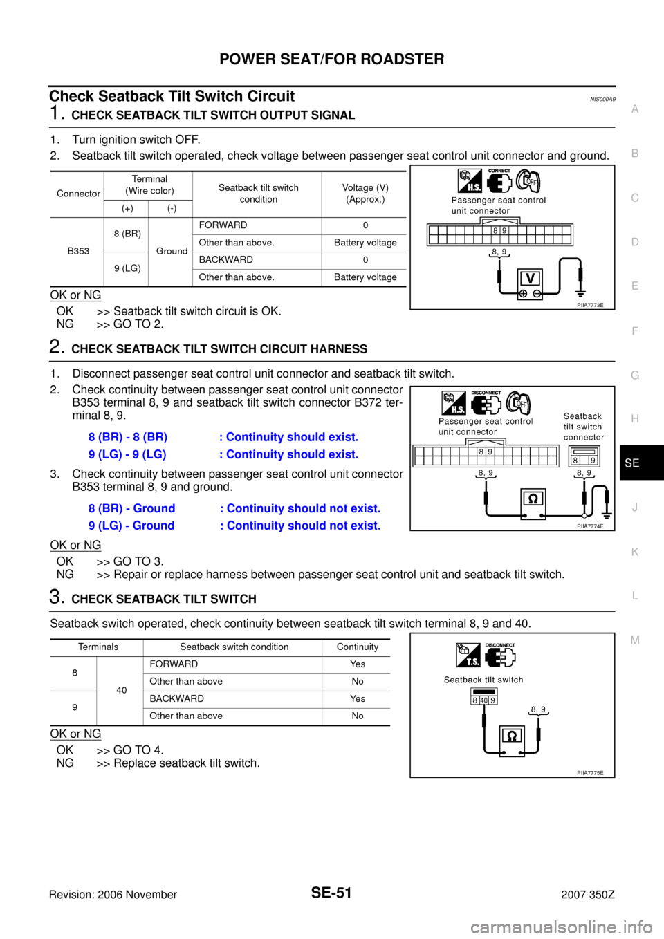
1. CHECK SEATBACK TILT SWITCH OUTPUT SIGNAL
1. Turn ignition switch OFF.
2. Seatback tilt switch operated, check voltage between passenger seat control unit connector and ground.
OK or NG
OK >> Seatback tilt switch circuit is OK.
NG >> GO TO 2.
2. CHECK SEATBACK TILT SWITCH CIRCUIT HARNESS
1. Disconnect passenger seat control unit connector and seatback tilt switch.
2. Check continuity between passenger seat control unit connector
B353 terminal 8, 9 and seatback tilt switch connector B372 ter-
minal 8, 9.
3. Check continuity between passenger seat control unit connector
B353 terminal 8, 9 and ground.
OK or NG
OK >> GO TO 3.
NG >> Repair or replace harness between passenger seat control unit and seatback tilt switch.
3. CHECK SEATBACK TILT SWITCH
Seatback switch operated, check continuity between seatback tilt switch terminal 8, 9 and 40.
OK or NG
OK >> GO TO 4.
NG >> Replace seatback tilt switch.
ConnectorTerminal
(Wire color)Seatback tilt switch
conditionVoltage (V)
(Approx.)
(+) (-)
B3538 (BR)
GroundFORWARD 0
Other than above. Battery voltage
9 (LG)BACKWARD 0
Other than above. Battery voltage
PIIA7773E
8 (BR) - 8 (BR) : Continuity should exist.
9 (LG) - 9 (LG) : Continuity should exist.
8 (BR) - Ground : Continuity should not exist.
9 (LG) - Ground : Continuity should not exist.
PIIA7774E
Terminals Seatback switch condition Continuity
8
40FORWARD Yes
Other than above No
9BACKWARD Yes
Other than above No
PIIA7775E
Page 53 of 80

POWER SEAT/FOR ROADSTER
SE-53
C
D
E
F
G
H
J
K
L
MA
B
SE
Revision: 2006 November2007 350Z
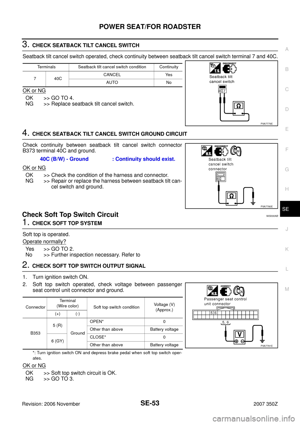
3. CHECK SEATBACK TILT CANCEL SWITCH
Seatback tilt cancel switch operated, check continuity between seatback tilt cancel switch terminal 7 and 40C.
OK or NG
OK >> GO TO 4.
NG >> Replace seatback tilt cancel switch.
4. CHECK SEATBACK TILT CANCEL SWITCH GROUND CIRCUIT
Check continuity between seatback tilt cancel switch connector
B373 terminal 40C and ground.
OK or NG
OK >> Check the condition of the harness and connector.
NG >> Repair or replace the harness between seatback tilt can-
cel switch and ground.
Check Soft Top Switch Circuit NIS000AB
1. CHECK SOFT TOP SYSTEM
Soft top is operated.
Operate normally?
Ye s > > G O T O 2 .
No >> Further inspection necessary. Refer to
2. CHECK SOFT TOP SWITCH OUTPUT SIGNAL
1. Turn ignition switch ON.
2. Soft top switch operated, check voltage between passenger
seat control unit connector and ground.
*: Turn ignition switch ON and depress brake pedal when soft top switch oper-
ates.
OK or NG
OK >> Soft top switch circuit is OK.
NG >> GO TO 3.
Terminals Seatback tilt cancel switch condition Continuity
7 40CCANCEL Yes
AUTO No
PIIA7779E
40C (B/W) - Ground : Continuity should exist.
PIIA7780E
ConnectorTerminal
(Wire color)
Soft top switch conditionVoltage (V)
(Approx.)
(+) (-)
B3535 (R)
GroundOPEN* 0
Other than above Battery voltage
6 (GY)CLOSE* 0
Other than above Battery voltage
PIIA7781E
Page 55 of 80

POWER SEAT/FOR ROADSTER
SE-55
C
D
E
F
G
H
J
K
L
MA
B
SE
Revision: 2006 November2007 350Z
Check Storage Lid Close Signal Circuit NIS000AD
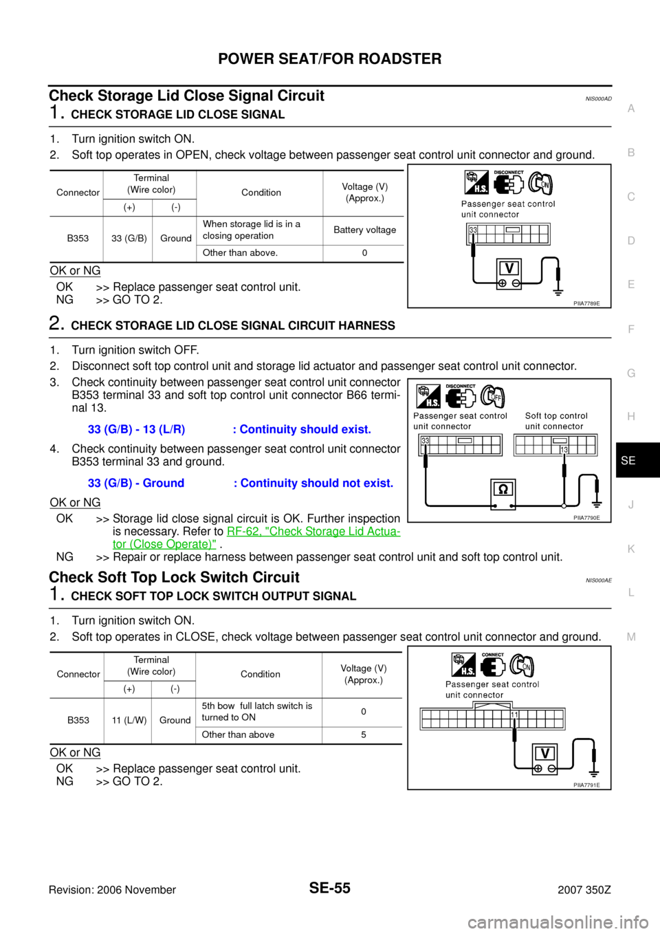
1. CHECK STORAGE LID CLOSE SIGNAL
1. Turn ignition switch ON.
2. Soft top operates in OPEN, check voltage between passenger seat control unit connector and ground.
OK or NG
OK >> Replace passenger seat control unit.
NG >> GO TO 2.
2. CHECK STORAGE LID CLOSE SIGNAL CIRCUIT HARNESS
1. Turn ignition switch OFF.
2. Disconnect soft top control unit and storage lid actuator and passenger seat control unit connector.
3. Check continuity between passenger seat control unit connector
B353 terminal 33 and soft top control unit connector B66 termi-
nal 13.
4. Check continuity between passenger seat control unit connector
B353 terminal 33 and ground.
OK or NG
OK >> Storage lid close signal circuit is OK. Further inspection
is necessary. Refer to RF-62, "
Check Storage Lid Actua-
tor (Close Operate)" .
NG >> Repair or replace harness between passenger seat control unit and soft top control unit.
Check Soft Top Lock Switch Circuit NIS000AE
1. CHECK SOFT TOP LOCK SWITCH OUTPUT SIGNAL
1. Turn ignition switch ON.
2. Soft top operates in CLOSE, check voltage between passenger seat control unit connector and ground.
OK or NG
OK >> Replace passenger seat control unit.
NG >> GO TO 2.
ConnectorTerminal
(Wire color)
ConditionVoltage (V)
(Approx.)
(+) (-)
B353 33 (G/B) GroundWhen storage lid is in a
closing operationBattery voltage
Other than above. 0
PIIA7789E
33 (G/B) - 13 (L/R) : Continuity should exist.
33 (G/B) - Ground : Continuity should not exist.
PIIA7790E
ConnectorTerminal
(Wire color)
ConditionVoltage (V)
(Approx.)
(+) (-)
B353 11 (L/W) Ground5th bow full latch switch is
turned to ON0
Other than above 5
PIIA7791E
Page 73 of 80

SEAT
SE-73
C
D
E
F
G
H
J
K
L
MA
B
SE
Revision: 2006 November2007 350Z
REMOVAL
When removing or installing the seat trim, carefully handle it to keep dirt out and avoid damage.
CAUTION:
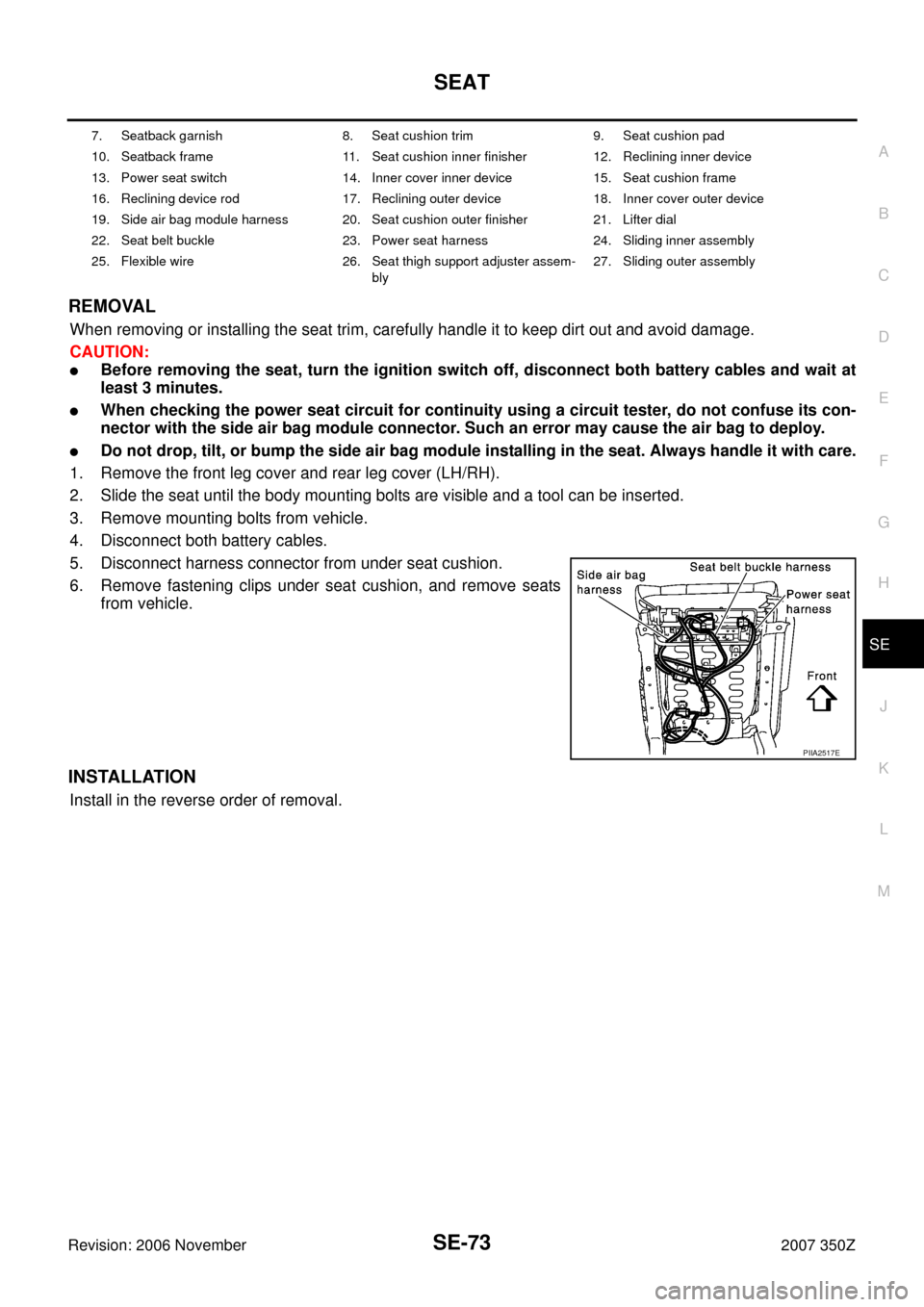
�Before removing the seat, turn the ignition switch off, disconnect both battery cables and wait at
least 3 minutes.
�When checking the power seat circuit for continuity using a circuit tester, do not confuse its con-
nector with the side air bag module connector. Such an error may cause the air bag to deploy.
�Do not drop, tilt, or bump the side air bag module installing in the seat. Always handle it with care.
1. Remove the front leg cover and rear leg cover (LH/RH).
2. Slide the seat until the body mounting bolts are visible and a tool can be inserted.
3. Remove mounting bolts from vehicle.
4. Disconnect both battery cables.
5. Disconnect harness connector from under seat cushion.
6. Remove fastening clips under seat cushion, and remove seats
from vehicle.
INSTALLATION
Install in the reverse order of removal.
7. Seatback garnish 8. Seat cushion trim 9. Seat cushion pad
10. Seatback frame 11. Seat cushion inner finisher 12. Reclining inner device
13. Power seat switch 14. Inner cover inner device 15. Seat cushion frame
16. Reclining device rod 17. Reclining outer device 18. Inner cover outer device
19. Side air bag module harness 20. Seat cushion outer finisher 21. Lifter dial
22. Seat belt buckle 23. Power seat harness 24. Sliding inner assembly
25. Flexible wire 26. Seat thigh support adjuster assem-
bly27. Sliding outer assembly
PIIA2517E
Page:
< prev 1-8 9-16 17-24