RSU-6
REAR SUSPENSION ASSEMBLY
Revision: 2006 November2007 350Z
THE ALIGNMENT PROCESS
IMPORTANT:
Use only the alignment specifications listed in this Service Manual.
�When displaying the alignment settings, many alignment machines use “indicators”: (Green/red, plus or
minus, Go/No Go). Do NOT use these indicators.
–The alignment specifications programmed into your machine that operate these indicators may not be cor-
rect.
–This may result in an ERROR.
�Some newer alignment machines are equipped with an optional “Rolling Compensation” method to “com-
pensate” the sensors (alignment targets or head units). DO NOT use this “Rolling Compensation”
method.
–Use the “Jacking Compensation Method”. After installing the alignment targets or head units, raise the
vehicle and rotate the wheels 1/2 turn both ways.
–See Instructions in the alignment machine you're using for more information on this.
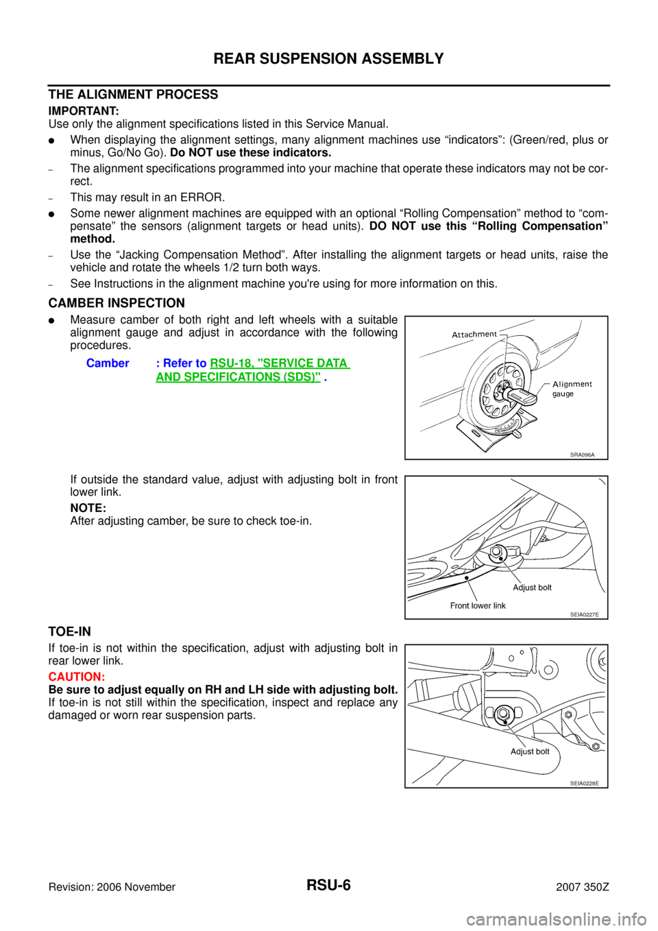
CAMBER INSPECTION
�Measure camber of both right and left wheels with a suitable
alignment gauge and adjust in accordance with the following
procedures.
If outside the standard value, adjust with adjusting bolt in front
lower link.
NOTE:
After adjusting camber, be sure to check toe-in.
TOE-IN
If toe-in is not within the specification, adjust with adjusting bolt in
rear lower link.
CAUTION:
Be sure to adjust equally on RH and LH side with adjusting bolt.
If toe-in is not still within the specification, inspect and replace any
damaged or worn rear suspension parts.Camber : Refer to RSU-18, "
SERVICE DATA
AND SPECIFICATIONS (SDS)" .
SRA096A
SEIA0227E
SEIA0228E
RSU-8
REAR SUSPENSION ASSEMBLY
Revision: 2006 November2007 350Z
Removal and InstallationNES0000R
REMOVAL
1. Remove tire with power tool.
2. Remove brake caliper with power tool. Hang it in a place where it will not interfere with work. Refer to BR-
39, "REAR DISC BRAKE" .
NOTE:
Avoid depressing brake pedal while brake caliper is removed.
3. Remove stabilizer bar. Refer to RSU-16, "
STABILIZER BAR" .
4. Remove rear exhaust tube. Refer to EX-3, "
EXHAUST SYSTEM" .
5. Remove rear propeller shaft. Refer to PR-5, "
REAR PROPELLER SHAFT" .
6. Separate attachment bolts between parking brake cable and vehicle and rear suspension member. Refer
to PB-4, "
PARKING BRAKE CONTROL" .
7. Remove wheel sensor from rear final drive.
8. Remove rear lower link and coil spring. Refer to RSU-15, "
REAR LOWER LINK & COIL SPRING" .
9. Remove fixing bolt in upper side of mounting seal bracket. Refer to RSU-9, "
SHOCK ABSORBER" .
10. Set jack under rear final drive.
11. Remove tunnel stay and member stay from vehicle.
12. Remove fixing bolts and nuts of rear pin stay and then remove rear pin stay from vehicle.
13. Gradually lowering jack, remove rear suspension assembly.
INSTALLATION
�Refer to RSU-7, "Components" for tightening torque. Install in the reverse order of removal.
NOTE:
Refer to component parts location and do not reuse non-reusable parts.
�Perform final tightening of installation position of links (rubber bushing) under unladen condition with tires
on level ground. Check wheel alignment. Refer to RSU-18, "
SERVICE DATA AND SPECIFICATIONS
(SDS)" .
1. Bushing 2. Mounting seal 3. Distance tube
4. Mounting seal bracket 5. Bushing 6. Bound bumper cover
7. Bound bumper 8. Shock absorber 9. Axle
10. Cotter pin 11. Upper seat 12. Coil spring
13. Ball seat 14. Rubber seat 15. Suspension arm
16. Stopper rubber 17. Stabilizer connecting rod mounting
bracket18. Stabilizer connecting rod
19. Rear pin stay 20. Rear suspension member 21. Rear lower link
22. Front lower link 23. Radius rod 24. Stabilizer bar
25. Stabilizer bushing 26. Stabilizer clamp 27. Member stay
28. Tunnel stay