Page 10 of 36

PS-10
STEERING COLUMN
Revision: 2006 November2007 350Z
STEERING COLUMNPFP:48810
Removal and InstallationNGS0000C
COMPONENTS
CAUTION:
�Care must be taken not to give axial impact to steering column assembly during removal and
installation.
�Care must be taken not to move steering gear during removal of steering column assembly.
REMOVAL
1. Set vehicle to the straight ahead-direction.
2. Remove driver air bag module from steering wheel. Refer to SRS-40, "
DRIVER AIR BAG MODULE" .
3. Disconnect steering switch connector, remove steering wheel lock nut, then remove steering wheel. Refer
to PS-7, "
STEERING WHEEL" .
4. Remove dash side finisher (LH). Refer to IP-10, "
INSTRUMENT PANEL ASSEMBLY" .
5. Remove instrument driver panel lower. Refer to IP-10, "
INSTRUMENT PANEL ASSEMBLY" .
6. Remove column lower cover and combination meter (which is connected with steering column upper
cover) from steering column assembly. Refer to DI-24, "
Removal and Installation for Combination Meter" .
1. Lower joint 2. Lower shaft 3. Hole cover
4. Clamp 5. Hole cover seal 6. Collar
7. Steering column assembly 8. Combination switch & spiral cable 9. Escutcheon
10. Column lower cover 11. Right lid 12. Combination meter & column upper cover
13. Steering wheel 14. Steering wheel lock nut 15. Left lid
16. Driver air bag module
SGIA0339E
Page 11 of 36

STEERING COLUMN
PS-11
C
D
E
F
H
I
J
K
L
MA
B
PS
Revision: 2006 November2007 350Z
7. Remove combination switch & spiral cable from steering column
assembly. Refer to SRS-42, "
Removal and Installation" .
8. Disconnect the following connector from steering column
assembly.
�Steering lock harness connector
�Ignition switch harness connector
�Key switch harness connector
9. Remove control unit with VDC/TCS/ABS control unit. Refer to
BRC-129, "
VDC/TCS/ABS CONTROL UNIT" .
10. Disconnect brake switch harness connector.
11. Remove steering column shaft from lower shaft in the following
procedure.
a. Remove lock nut from yoke.
b. Turn steering wheel to the right to appear the head of bolt.
c. Remove the fixed part of collar for bolt to the outside of its head,
remove bolt.
d. Remove the set lib of steering column assembly side from yoke,
push it equal to the thick part of yoke.
NOTE:
Because collar is set in lower shaft, if the set lib is pushed
(action), joint center will be lifted in the opposite direction (reac-
tion), and then the set lib will be in squeezed to the thick part of
yoke.
SGIA0368E
SGIA0724E
SGIA0353E
SGIA0354E
Page 12 of 36
PS-12
STEERING COLUMN
Revision: 2006 November2007 350Z
e. Yoke will be removed from collar, when steering column assem-
bly is lifted about 45° oblique upward.
f. Collar remains on lower shaft.
12. Remove bolts and nut from steering member, remove steering
column assembly from steering member.
13. Remove collar from lower shaft.
14. Remove hole cover seal from lower shaft.
15. Remove mounting bolts, then remove hole cover from panel.
16. Raise vehicle, then loosen bolt for lower yoke of lower joint and
remove joint together with lower shaft.
SGIA0355E
SGIA0356E
SGIA0373E
SGIA0765E
Page 13 of 36
STEERING COLUMN
PS-13
C
D
E
F
H
I
J
K
L
MA
B
PS
Revision: 2006 November2007 350Z
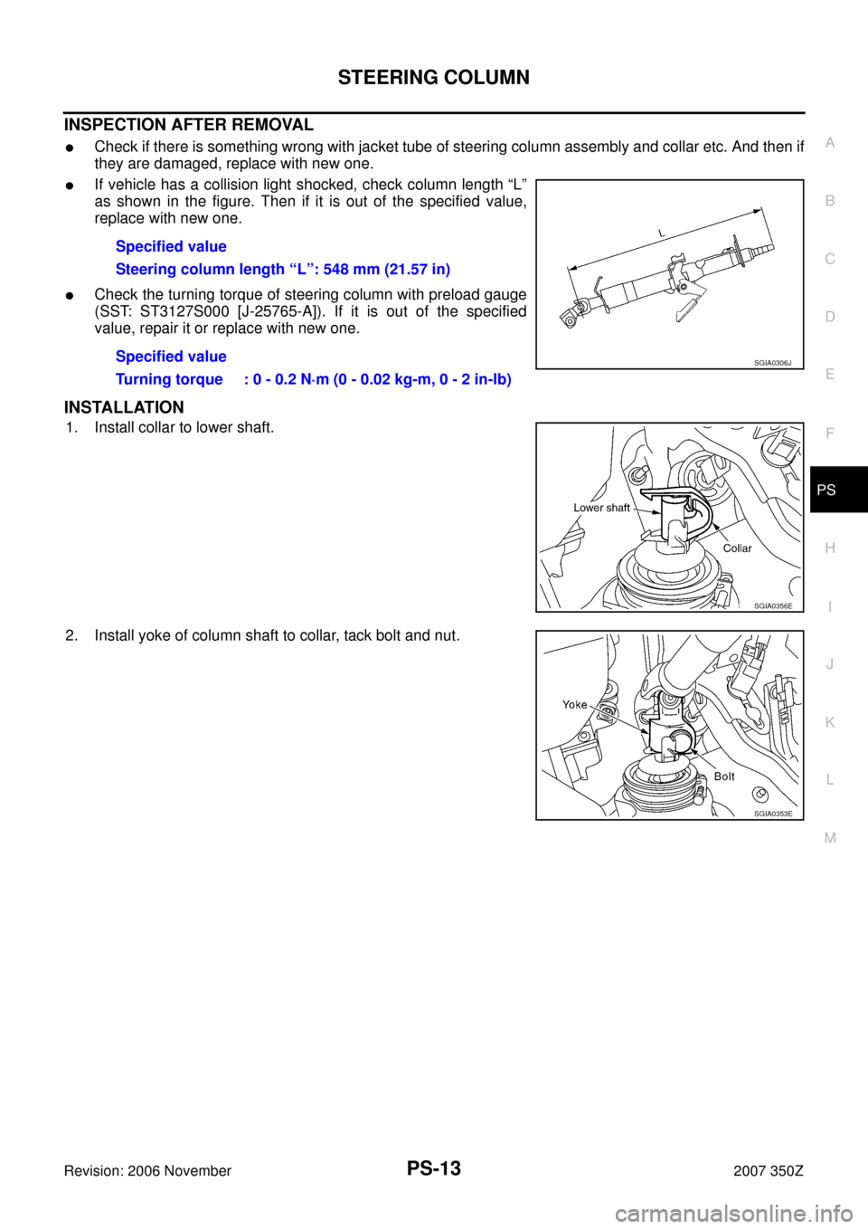
INSPECTION AFTER REMOVAL
�Check if there is something wrong with jacket tube of steering column assembly and collar etc. And then if
they are damaged, replace with new one.
�If vehicle has a collision light shocked, check column length “L”
as shown in the figure. Then if it is out of the specified value,
replace with new one.
�Check the turning torque of steering column with preload gauge
(SST: ST3127S000 [J-25765-A]). If it is out of the specified
value, repair it or replace with new one.
INSTALLATION
1. Install collar to lower shaft.
2. Install yoke of column shaft to collar, tack bolt and nut.Specified value
Steering column length “L”: 548 mm (21.57 in)
Specified value
Turning torque : 0 - 0.2 N·m (0 - 0.02 kg-m, 0 - 2 in-lb)
SGIA0306J
SGIA0356E
SGIA0353E
Page 14 of 36
PS-14
STEERING COLUMN
Revision: 2006 November2007 350Z
3. Put steering column assembly (installation hole “P”) on bolt for
steering member side and install nut “A” then tighten it together
with the other bolts at the specified torque.
4. Connect yoke and collar with bolt, tighten nut at the specified
torque.
INSPECTION AFTER INSTALLATION
�After installing steering column to vehicle, check tilt device and
its operation range “L
1” , “L2” .
�Check if steering operation can turn to the end of the left and
right smoothly.
SGIA0371E
Tilt operating range “L1 ” : 28 - 32 mm (1.10 - 1.26 in)
“L
2 ” : 13 - 17 mm (0.51 - 0.67 in)
SGIA1456E
Page 15 of 36
STEERING COLUMN
PS-15
C
D
E
F
H
I
J
K
L
MA
B
PS
Revision: 2006 November2007 350Z
Disassembly and AssemblyNGS0000D
COMPONENTS
DISASSEMBLY
1. Remove steering column shaft lock nut, then remove steering column shaft from front side of jacket tube.
2. Remove tilt device from jacket tube.
3. Remove lock nut and adjusting stopper according to the following procedure.
a. Turn tilt lever to the unlock side.
b. Remove spring from column mounting bracket.
1. Steering column shaft 2. Adjusting bolt 3. Adjusting stopper
4. Jacket tube 5. Steering column shaft lock nut 6. Spring
7. Column mounting bracket 8. Tilt lever stopper 9. Tilt lever
10. Lock nut
SGIA0340E
SGIA0742E
Page 16 of 36

PS-16
STEERING COLUMN
Revision: 2006 November2007 350Z
c. Lock adjusting bolt, then remove lock nut.
d. Remove adjusting bolt, adjusting stopper, column mounting
bracket, tilt lever stopper and tilt lever from jacket tube.
INSPECTION AFTER DISASSEMBLY
�Check if there is something wrong with steering column shaft and bearing. And then if they are damaged,
replace with new one.
�Check if there is something wrong with the component of tilt device. And then if it is damaged, replace
with new one.
ASSEMBLY
1. Install tilt device to jacket tube. Refer to PS-15, "Disassembly and Assembly" .
NOTE:
�Turn tilt lever to unlock side while at work to make it easier.
�That can avoid column shaft's sudden descent when tilt lever
is operated on vehicle.
2. When tilt lever is in the locked position (operation range is about
40°), tighten lock nut at the specified torque to make tilt lever
locked.
3. Apply grease to the part shown in the figure of component. Refer
to PS-15, "
Disassembly and Assembly" .
4. Install steering column shaft to jacket tube, tighten steering col-
umn shaft lock nut at the specified torque.
SGIA0343E
SGIA0344E
SGIA0346E
Tightening torque:
13.5 - 18.6 N·m (1.4 - 1.8 kg-m, 10 - 13 ft-lb)
Tightening torque : 25 - 34 N·m (2.6 - 3.4 kg-m, 19 - 25 ft-lb)
SGIA0347E
Page 17 of 36

POWER STEERING GEAR AND LINKAGE
PS-17
C
D
E
F
H
I
J
K
L
MA
B
PS
Revision: 2006 November2007 350Z
POWER STEERING GEAR AND LINKAGEPFP:49001
Removal and InstallationNGS0000E
COMPONENTS
CAUTION:
Spiral cable may snap due to steering operation if steering column is separated from steering gear
assembly. Therefore fix steering wheel with a string to avoid turns.
REMOVAL
1. Set wheels in the straight-ahead position.
2. Remove undercover and tires from vehicle with power tool.
3. Remove front crossbar. Refer to FSU-8, "
Components" .
4. Confirm slit of lower joints fits with the projection on rear cover
cap, furthermore marking position on steering gear assembly
nearly fits with the projection on rear cover cap.
5. Remove cotter pin at steering outer socket, then loosen mount-
ing nut.
6. Use a ball joint remover (SST) to remove steering outer socket
from steering knuckle. Be careful not to damage ball joint boot.
CAUTION:
Tighten temporarily mounting nut to prevent damage to
threads and to prevent ball joint remover (SST) from com-
ing off.
7. Remove oil pipings (high pressure side and low pressure side)
from steering gear assembly, then drain fluid from pipings.
1. Cotter pin 2. Steering gear assembly 3. Rack mounting insulator
4. Rack mounting bracket
Refer to GI-11, "
Components" , for the symbols in the figure.
SGIA1471E
SGIA0349E
SGIA0341E

 on bolt for
steering member side and install nut “A” then tighten it together
wit")
