GI-28
SERVICE INFORMATION FOR ELECTRICAL INCIDENT
Revision: 2006 November2007 350Z
�Freezing
�Water intrusion
�Electrical load
�Cold or hot start up
Get a thorough description of the incident from the customer. It is important for simulating the conditions of the
problem.
Vehicle Vibration
The problem may occur or become worse while driving on a rough road or when engine is vibrating (idle with
A/C on). In such a case, you will want to check for a vibration related condition. Refer to the following illustra-
tion.
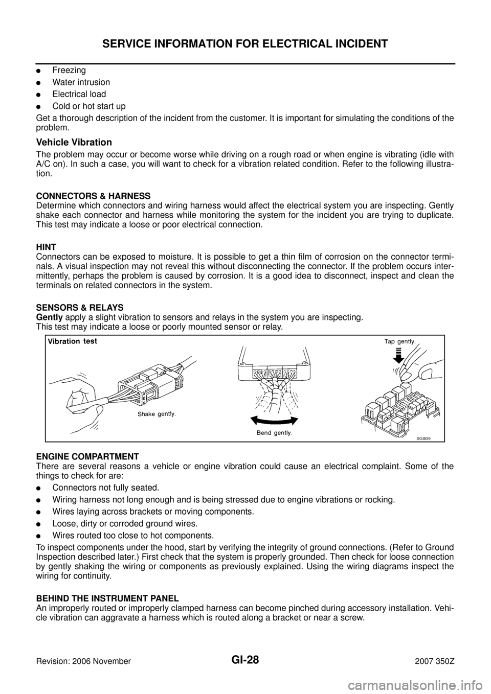
CONNECTORS & HARNESS
Determine which connectors and wiring harness would affect the electrical system you are inspecting. Gently
shake each connector and harness while monitoring the system for the incident you are trying to duplicate.
This test may indicate a loose or poor electrical connection.
HINT
Connectors can be exposed to moisture. It is possible to get a thin film of corrosion on the connector termi-
nals. A visual inspection may not reveal this without disconnecting the connector. If the problem occurs inter-
mittently, perhaps the problem is caused by corrosion. It is a good idea to disconnect, inspect and clean the
terminals on related connectors in the system.
SENSORS & RELAYS
Gently apply a slight vibration to sensors and relays in the system you are inspecting.
This test may indicate a loose or poorly mounted sensor or relay.
ENGINE COMPARTMENT
There are several reasons a vehicle or engine vibration could cause an electrical complaint. Some of the
things to check for are:
�Connectors not fully seated.
�Wiring harness not long enough and is being stressed due to engine vibrations or rocking.
�Wires laying across brackets or moving components.
�Loose, dirty or corroded ground wires.
�Wires routed too close to hot components.
To inspect components under the hood, start by verifying the integrity of ground connections. (Refer to Ground
Inspection described later.) First check that the system is properly grounded. Then check for loose connection
by gently shaking the wiring or components as previously explained. Using the wiring diagrams inspect the
wiring for continuity.
BEHIND THE INSTRUMENT PANEL
An improperly routed or improperly clamped harness can become pinched during accessory installation. Vehi-
cle vibration can aggravate a harness which is routed along a bracket or near a screw.
SGI839
GI-36
CONSULT-III/GST CHECKING SYSTEM
Revision: 2006 November2007 350Z
CONSULT-III/GST CHECKING SYSTEMPFP:00000
DescriptionNAS000A4
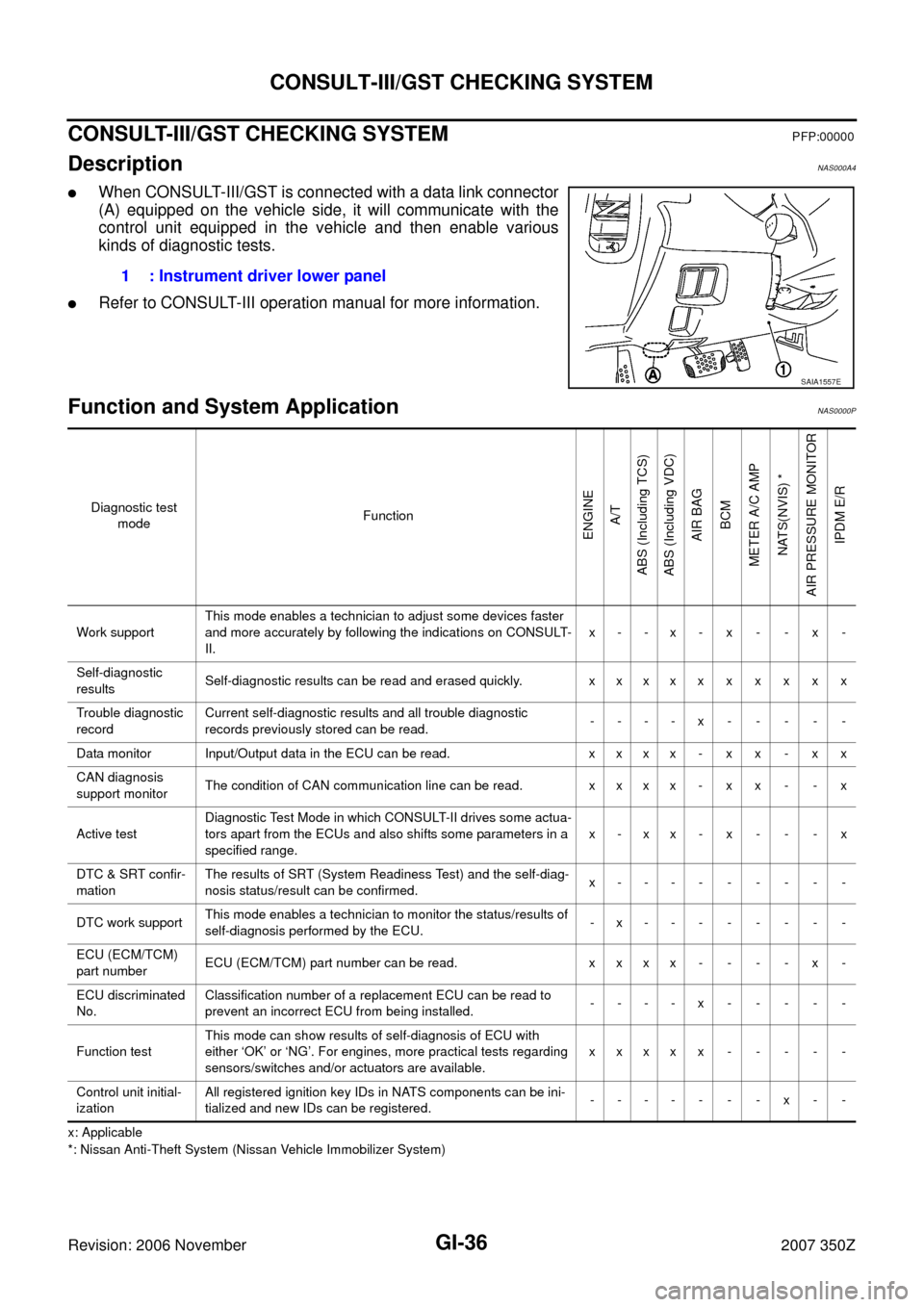
�When CONSULT-III/GST is connected with a data link connector
(A) equipped on the vehicle side, it will communicate with the
control unit equipped in the vehicle and then enable various
kinds of diagnostic tests.
�Refer to CONSULT-III operation manual for more information.
Function and System Application NAS0000P
x: Applicable
*: Nissan Anti-Theft System (Nissan Vehicle Immobilizer System)
1 : Instrument driver lower panel
SAIA1557E
Diagnostic test
modeFunction
ENGINE
A/T
ABS (Including TCS)
ABS (Including VDC)
AIR BAG
BCM
METER A/C AMP
NATS(NVIS) *
AIR PRESSURE MONITOR
IPDM E/R
Work supportThis mode enables a technician to adjust some devices faster
and more accurately by following the indications on CONSULT-
II.x- -x- x - - x -
Self-diagnostic
resultsSelf-diagnostic results can be read and erased quickly. x x x x x x x x x x
Trouble diagnostic
recordCurrent self-diagnostic results and all trouble diagnostic
records previously stored can be read.----x-----
Data monitor Input/Output data in the ECU can be read. x x x x - x x - x x
CAN diagnosis
support monitorThe condition of CAN communication line can be read. x x x x - x x - - x
Active testDiagnostic Test Mode in which CONSULT-II drives some actua-
tors apart from the ECUs and also shifts some parameters in a
specified range.x-xx-x- - -x
DTC & SRT confir-
mationThe results of SRT (System Readiness Test) and the self-diag-
nosis status/result can be confirmed.x---------
DTC work supportThis mode enables a technician to monitor the status/results of
self-diagnosis performed by the ECU.-x--------
ECU (ECM/TCM)
part numberECU (ECM/TCM) part number can be read. x x x x - - - - x -
ECU discriminated
No.Classification number of a replacement ECU can be read to
prevent an incorrect ECU from being installed.----x-----
Function testThis mode can show results of self-diagnosis of ECU with
either ‘OK’ or ‘NG’. For engines, more practical tests regarding
sensors/switches and/or actuators are available.xxxxx-----
Control unit initial-
izationAll registered ignition key IDs in NATS components can be ini-
tialized and new IDs can be registered.---- - - -x - -