GI-4
PRECAUTIONS
Revision: 2006 November2007 350Z
�Before jacking up the vehicle, apply wheel chocks or other tire
blocks to the wheels to prevent the vehicle from moving. After
jacking up the vehicle, support the vehicle weight with safety
stands at the points designated for proper lifting before working
on the vehicle.
These operations should be done on a level surface.
�When removing a heavy component such as the engine or tran-
saxle/transmission, be careful not to lose your balance and drop
them. Also, do not allow them to strike adjacent parts, especially
the brake tubes and master cylinder.
�Before starting repairs which do not require battery power:
Turn off ignition switch.
Disconnect the negative battery terminal.
�If the battery terminals are disconnected, recorded memory of
radio and each control unit is erased.
�Battery posts, terminals and related accessories contain lead
and lead compounds. Wash hands after handling.
�To prevent serious burns:
Avoid contact with hot metal parts.
Do not remove the radiator cap when the engine is hot.
�Dispose of or recycle drained oil or the solvent used for cleaning
parts in an appropriate manner.
�Do not attempt to top off the fuel tank after the fuel pump nozzle
shuts off automatically.
Continued refueling may cause fuel overflow, resulting in fuel
spray and possibly a fire.
�Clean all disassembled parts in the designated liquid or solvent
prior to inspection or assembly.
�Replace oil seals, gaskets, packings, O-rings, locking washers, cotter pins, self-locking nuts, etc. with new
ones.
�Replace inner and outer races of tapered roller bearings and needle bearings as a set.
�Arrange the disassembled parts in accordance with their assembled locations and sequence.
�Do not touch the terminals of electrical components which use microcomputers (such as ECM).
Static electricity may damage internal electronic components.
�After disconnecting vacuum or air hoses, attach a tag to indicate the proper connection.
�Use only the fluids and lubricants specified in this manual.
�Use approved bonding agent, sealants or their equivalents when required.
�Use hand tools, power tools (disassembly only) and recom-
mended special tools where specified for safe and efficient ser-
vice repairs.
�When repairing the fuel, oil, water, vacuum or exhaust systems,
check all affected lines for leaks.
SGI231
SEF289H
SGI233
PBIC0190E
GI-12
HOW TO USE THIS MANUAL
Revision: 2006 November2007 350Z
How to Follow Trouble DiagnosesNAS0000I
DESCRIPTION
NOTICE:
Trouble diagnoses indicate work procedures required to diagnose problems effectively. Observe the following
instructions before diagnosing.
1.Before performing trouble diagnoses, read the “Preliminary Check”, the “Symptom Chart” or the
“Work Flow”.
2.After repairs, re-check that the problem has been completely eliminated.
3.Refer to Component Parts and Harness Connector Location for the Systems described in each
section for identification/location of components and harness connectors.
4.Refer to the Circuit Diagram for quick pinpoint check.
If you need to check circuit continuity between harness connectors in more detail, such as when a
sub-harness is used, refer to Wiring Diagram in each individual section and Harness Layout in PG
section for identification of harness connectors.
5.When checking circuit continuity, ignition switch should be OFF.
6.Before checking voltage at connectors, check battery voltage.
7.After accomplishing the Diagnostic Procedures and Electrical Components Inspection, make sure
that all harness connectors are reconnected as they were.
HOW TO FOLLOW TEST GROUPS IN TROUBLE DIAGNOSES
1.Work and diagnostic procedure
Start to diagnose a problem using procedures indicated in enclosed test groups.
2.Questions and required results
Questions and required results are indicated in bold type in test group.
The meaning of are as follows:
SAIA0256E
GI-18
HOW TO USE THIS MANUAL
Revision: 2006 November2007 350Z
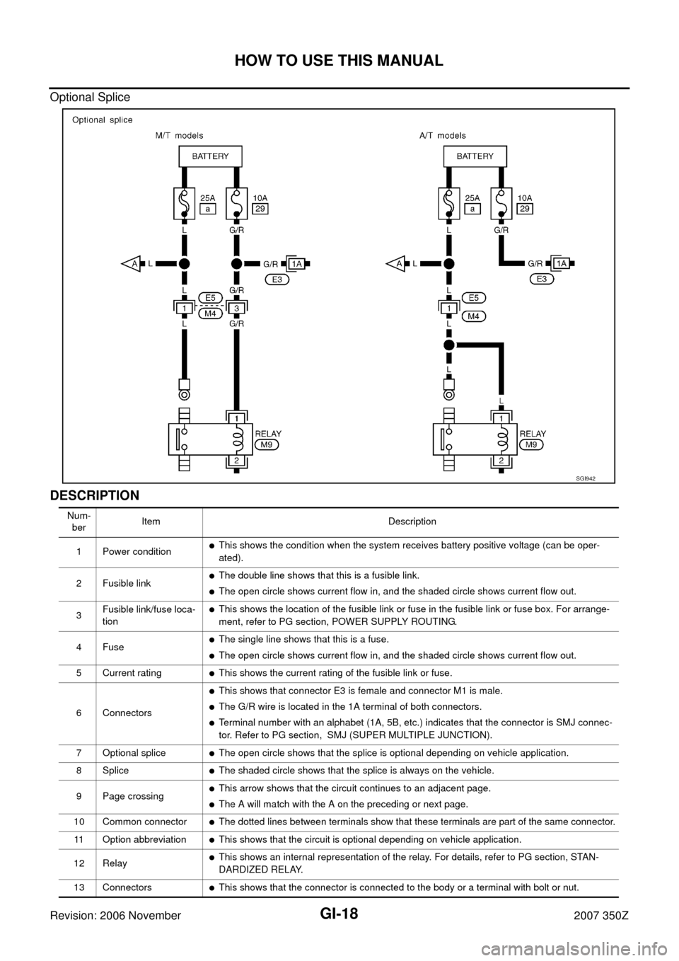
Optional Splice
DESCRIPTION
SGI942
Num-
berItem Description
1 Power condition
�This shows the condition when the system receives battery positive voltage (can be oper-
ated).
2 Fusible link
�The double line shows that this is a fusible link.
�The open circle shows current flow in, and the shaded circle shows current flow out.
3Fusible link/fuse loca-
tion
�This shows the location of the fusible link or fuse in the fusible link or fuse box. For arrange-
ment, refer to PG section, POWER SUPPLY ROUTING.
4Fuse
�The single line shows that this is a fuse.
�The open circle shows current flow in, and the shaded circle shows current flow out.
5 Current rating
�This shows the current rating of the fusible link or fuse.
6 Connectors
�This shows that connector E3 is female and connector M1 is male.
�The G/R wire is located in the 1A terminal of both connectors.
�Terminal number with an alphabet (1A, 5B, etc.) indicates that the connector is SMJ connec-
tor. Refer to PG section, SMJ (SUPER MULTIPLE JUNCTION).
7 Optional splice
�The open circle shows that the splice is optional depending on vehicle application.
8 Splice
�The shaded circle shows that the splice is always on the vehicle.
9 Page crossing
�This arrow shows that the circuit continues to an adjacent page.
�The A will match with the A on the preceding or next page.
10 Common connector
�The dotted lines between terminals show that these terminals are part of the same connector.
11 Option abbreviation
�This shows that the circuit is optional depending on vehicle application.
12 Relay
�This shows an internal representation of the relay. For details, refer to PG section, STAN-
DARDIZED RELAY.
13 Connectors
�This shows that the connector is connected to the body or a terminal with bolt or nut.