FAX-2
PREPARATION
Revision: 2006 November2007 350Z
PREPARATIONPFP:00002
Special Service ToolsNDS0000N
The actual shapes of Kent-Moore tools may differ from those of special service tools illustrated here.
Commercial Service ToolsNDS0000O
Tool number
(Kent-Moore No.)
Tool nameDescription
HT72520000
(J-25730-A)
Ball joint remover
a: 33 mm (1.30 in)
b: 50 mm (1.97 in)
r: 11.5 mm (0.453 in)Removing steering outer socket
ST3127S000
(J-25765-A)
Preload gaugeMeasuring rotating torque of ball joint
NT546
ZZA0806D
Tool nameDescription
Power toolLoosening bolts and nuts
PBIC0190E
FRONT WHEEL HUB AND KNUCKLE
FAX-5
C
E
F
G
H
I
J
K
L
MA
B
FA X
Revision: 2006 November2007 350Z
8. Use a ball joint remover to remove steering outer socket from
steering knuckle. Be careful not to damage ball joint boot.
CAUTION:
Tighten temporarily mounting nut to prevent damage to
threads and to prevent ball joint remover (SST) from com-
ing off.
9. After removing upper link, transverse link, compression rod and
cotter pin at steering knuckle, loosen mounting nut.
10. Use a ball joint remover (suitable tool) to remove upper link,
transverse link and compression rod from steering knuckle. Be
careful not to damage ball joint boot.
CAUTION:
Tighten temporarily mounting nut to prevent damage to threads and to prevent ball joint remover
(suitable tool) from coming off.
11. Remove steering knuckle and wheel hub and bearing assembly fixing bolt.
12. Remove wheel hub and bearing assembly from steering knuckle.
INSPECTION AFTER REMOVAL
�About the inspection for upper link, compression rod, steering outer socket, refer to FSU-14, "UPPER
LINK" , FSU-16, "COMPRESSION ROD" , PS-17, "POWER STEERING GEAR AND LINKAGE" .
Visual Inspection
�Check steering knuckle and ball seat for deformation, cracks, and other damage. Replace steering
knuckle and ball seat if cracks, deformation or other damage is found.
�Check ball joint boot for deformation, damage, and also for grease leakage. Replace steering knuckle
assembly if cracks, deformation or also for grease leakage is found.
Steering Knuckle Ball Joint Inspection
�Manually move ball stud to confirm it moves smoothly with no binding.
Swing Torque Inspection
CAUTION:
Before measurement, move ball joint at least ten times by hand to check for smooth movement.
�Hook spring balance at cotter pin mounting hole. Confirm spring
balance measurement value is within specifications when ball
stud begins moving.
�If it is outside the standard, replace steering knuckle.
Rotating Torque Inspection
�Attach mounting nut to ball stud. Check that rotating torque is
within specifications with a preload gauge.
�If it is outside the standard, replace steering knuckle.
SGIA0341E
Swing force:
0.147 - 1.4 N·m (0.02 - 0.14 kg-m, 2 - 12 in-lb)
Spring balance measurement
2.23 - 21.2 N (0.22 - 2.16 kg, 0.50 - 4.77 lb)
SEIA0523E
Tool number A: ST3127S000 (J−25765−A)
Rotating torque:
0.147 - 1.4 N·m (0.02 - 0.14 kg-m, 2 - 12 in-lb)
PDIA1258E
FAX-6
FRONT WHEEL HUB AND KNUCKLE
Revision: 2006 November2007 350Z
Axial End Play Inspection
�Move tip of ball joint in axial direction to check for looseness.
�If it is outside the standard, replace steering knuckle.
INSTALLATION
�Refer to FAX-4, "Removal and Installation" for tightening torque. Install in the reverse order of removal.
NOTE:
Refer to component parts location and do not reuse non-reusable parts.
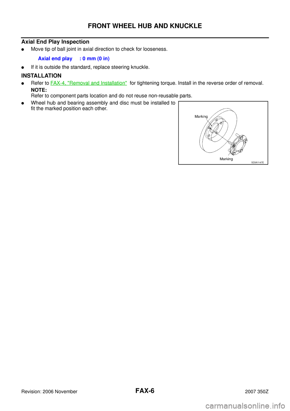
�Wheel hub and bearing assembly and disc must be installed to
fit the marked position each other.Axial end play : 0 mm (0 in)
SDIA1147E
SERVICE DATA AND SPECIFICATIONS (SDS)
FAX-7
C
E
F
G
H
I
J
K
L
MA
B
FA X
Revision: 2006 November2007 350Z
SERVICE DATA AND SPECIFICATIONS (SDS)PFP:00030
Wheel BearingNDS0000S
BALL JOINT
Axial end play0.05 mm (0.002 in) or less
Swing force 0.147 - 1.4 N·m (0.02 - 0.14 kg-m, 2 - 12 in-lb)
Measurement on spring balance (Spring balance hooking posi-
tion: cotter pin mounting hole)2.23 - 21.2 N (0.22 - 2.16 kg, 0.50 - 4.77 lb)
Rotating torque 0.147 - 1.4 N·m (0.02 - 0.14 kg-m, 2 - 12 in-lb)
Axial end play0 mm (0 in)


FAX-7
C
E
F
G
H
I
J
K
L
MA
B
FA X
Revision: 2006 November2007 350Z
SERVICE DATA AND SPECIFICATIONS (SDS)PFP:00030
Wheel BearingNDS0000S
BALL JOINT
Axial end play0")