Page 17 of 30
RADIATOR (ALUMINUM TYPE)
CO-17
C
D
E
F
G
H
I
J
K
L
MA
CO
Revision: 2006 November2007 350Z
RADIATOR (ALUMINUM TYPE)PFP:21460
Disassembly and AssemblyNBS0001Z
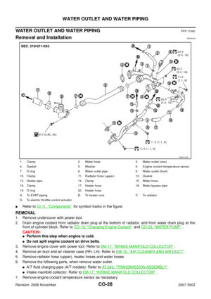
�Refer to GI-11, "Components" for symbol marks in the figure.
PREPARATION
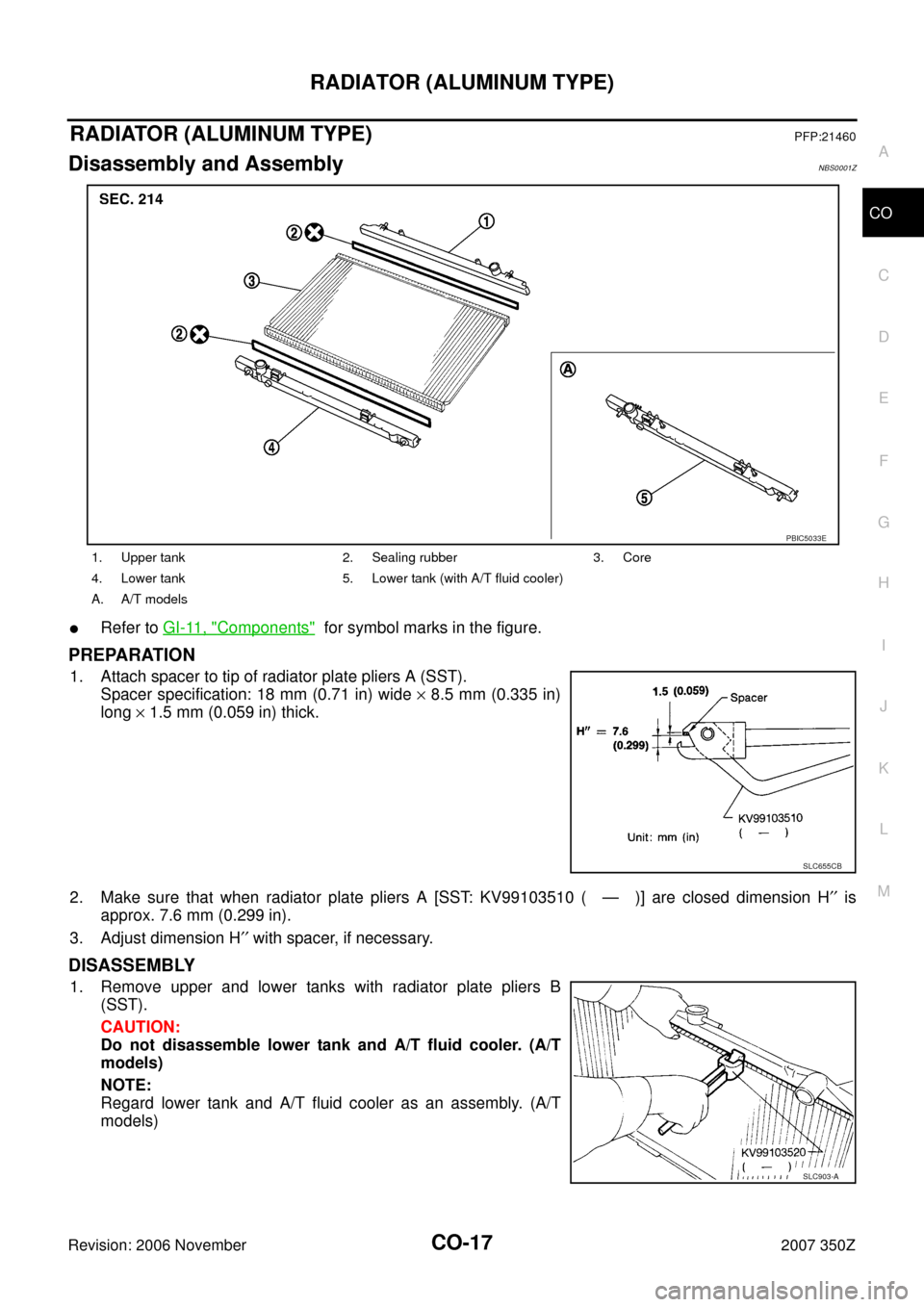
1. Attach spacer to tip of radiator plate pliers A (SST).
Spacer specification: 18 mm (0.71 in) wide × 8.5 mm (0.335 in)
long × 1.5 mm (0.059 in) thick.
2. Make sure that when radiator plate pliers A [SST: KV99103510 ( — )] are closed dimension H′′ is
approx. 7.6 mm (0.299 in).
3. Adjust dimension H′′ with spacer, if necessary.
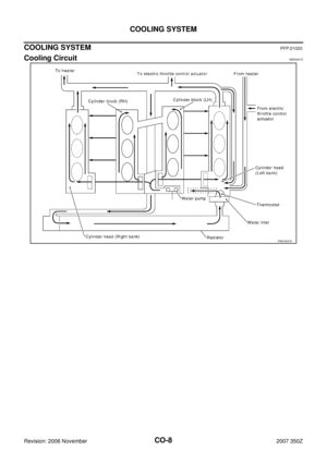
DISASSEMBLY
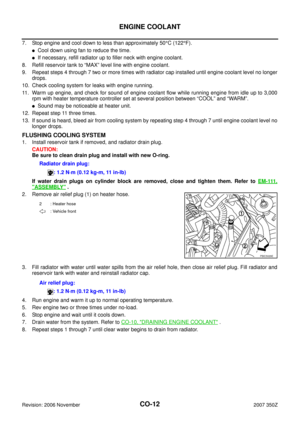
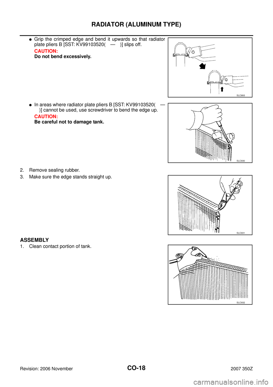
1. Remove upper and lower tanks with radiator plate pliers B
(SST).
CAUTION:
Do not disassemble lower tank and A/T fluid cooler. (A/T
models)
NOTE:
Regard lower tank and A/T fluid cooler as an assembly. (A/T
models)
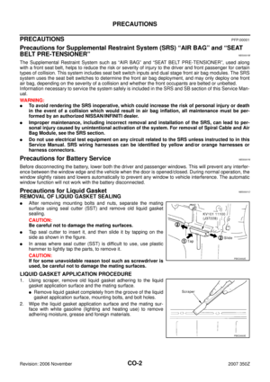
1. Upper tank 2. Sealing rubber 3. Core
4. Lower tank 5. Lower tank (with A/T fluid cooler)
A. A/T models
PBIC5033E
SLC655CB
SLC903-A
Page 18 of 30
CO-18
RADIATOR (ALUMINUM TYPE)
Revision: 2006 November2007 350Z
�Grip the crimped edge and bend it upwards so that radiator
plate pliers B [SST: KV99103520( — )] slips off.
CAUTION:
Do not bend excessively.
�In areas where radiator plate pliers B [SST: KV99103520( —
)] cannot be used, use screwdriver to bend the edge up.
CAUTION:
Be careful not to damage tank.
2. Remove sealing rubber.
3. Make sure the edge stands straight up.
ASSEMBLY
1. Clean contact portion of tank.
SLC893
SLC930
SLC931
SLC932
Page 19 of 30
RADIATOR (ALUMINUM TYPE)
CO-19
C
D
E
F
G
H
I
J
K
L
MA
CO
Revision: 2006 November2007 350Z
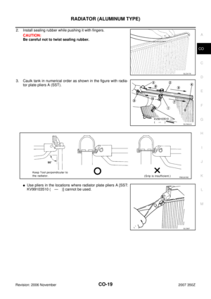
2. Install sealing rubber while pushing it with fingers.
CAUTION:
Be careful not to twist sealing rubber.
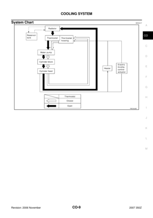
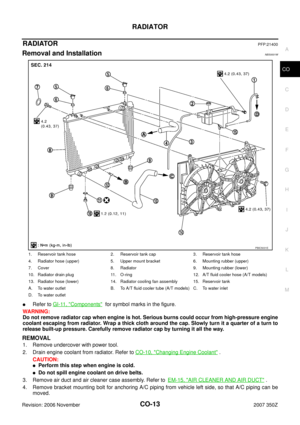
3. Caulk tank in numerical order as shown in the figure with radia-
tor plate pliers A (SST).
�Use pliers in the locations where radiator plate pliers A [SST:
KV99103510 ( — )] cannot be used.
SLC917A
SLC904-A
PBIC2076E
SLC897
Page 20 of 30

Revision: 2006 November2007 350Z
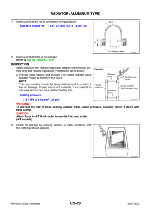
4. Make sure that the rim is completely crimped down.
5. Make sure that there is no leakage.
Refer to CO-20, \"
INSPECTION\" .
INSPECTION")
CO-20
RADIATOR (ALUMINUM TYPE)
Revision: 2006 November2007 350Z
4. Make sure that the rim is completely crimped down.
5. Make sure that there is no leakage.
Refer to CO-20, "
INSPECTION" .
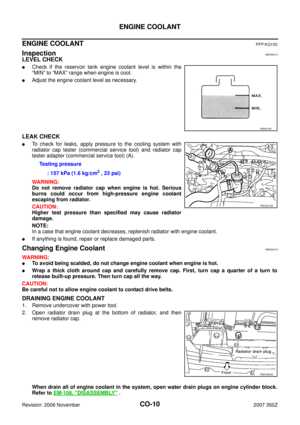
INSPECTION
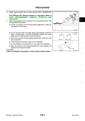
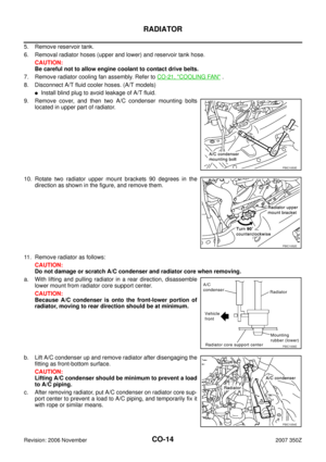
1. Apply pressure with radiator cap tester adapter (commercial ser-
vice tool) and radiator cap tester (commercial service tool).
�Provide used radiator and connect it to tested radiator using
radiator hoses as shown in the figure.
NOTE:
The used radiator should be tested beforehand to confirm it
has no leakage. If used one is not available, it is possible to
use new service part as a radiator testing tool.
WARNING:
To prevent the risk of hose coming undone while under pressure, securely fasten it down with
hose clamp.
CAUTION:
Attach hose to A/T fluid cooler to seal its inlet and outlet.
(A/T models)
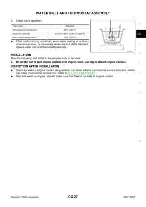
2. Check for leakage by soaking radiator in water container with
the testing pressure applied.Standard height “H” : 8.0 - 8.4 mm (0.315 - 0.331 in)
SLC554A
Testing pressure
: 157 kPa (1.6 kg/cm
2 , 23 psi)PBIC5158E
PBIC1699E
Page 21 of 30

COOLING FAN
CO-21
C
D
E
F
G
H
I
J
K
L
MA
CO
Revision: 2006 November2007 350Z
COOLING FANPFP:21140
Removal and InstallationNBS00020
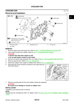
REMOVAL
1. Remove engine cover with power tool. Refer to EM-17, "INTAKE MANIFOLD COLLECTOR" .
2. Drain engine coolant from radiator. Refer to CO-10, "
Changing Engine Coolant" .
CAUTION:
�Perform this step when engine is cold.
�Do not spill engine coolant on drive belts.
3. Remove air cleaner case assembly (RH, LH). Refer to EM-15, "
AIR CLEANER AND AIR DUCT" .
4. Remove reservoir tank. Refer to CO-13, "
RADIATOR" .
5. Disconnect radiator hose (upper) at radiator side. Refer to CO-13, "
RADIATOR" .
6. Disconnect fan motor harness connectors at the right-lower por-
tion of fan shroud.
7. Remove mounting bolts to lift up and radiator cooling fan assembly.
CAUTION:
Be careful not to damage or scratch on radiator core.
INSTALLATION
Installation is the reverse order of removal.
NOTE:
Cooling fans are controlled by ECM. For details, refer to EC-543, "
DTC P1217 ENGINE OVER TEMPERA-
TURE" .
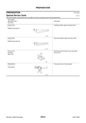
1. Cooling fan (RH) 2. Cooling fan (LH) 3. Fan shroud
4. Fan motor
PBIC2609E
PBIC1935E
Page 22 of 30
CO-22
COOLING FAN
Revision: 2006 November2007 350Z
Disassembly and Assembly NBS00021
DISASSEMBLY
1. Remove cooling fans (RH and LH) from fan motors.
2. Remove fan motors from fan shroud.
INSPECTION AFTER DISASSEMBLY
Cooling Fan
Inspect cooling fan for crack or unusual bend.
�If anything is found, replace cooling fan.
ASSEMBLY
Assembly is the reverse order of disassembly.
CAUTION:
RH and LH cooling fans are different. Be careful not to misassemble them.
Page 23 of 30

WATER PUMP
CO-23
C
D
E
F
G
H
I
J
K
L
MA
CO
Revision: 2006 November2007 350Z
WAT E R P U MPPFP:21020
Removal and InstallationNBS00022
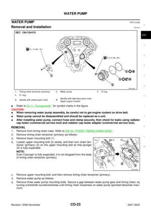
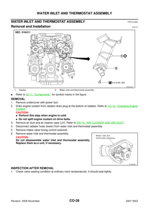
�Refer to GI-11, "Components" for symbol marks in the figure.
CAUTION:
�When removing water pump assembly, be careful not to get engine coolant on drive belt.
�Water pump cannot be disassembled and should be replaced as a unit.
�After installing water pump, connect hose and clamp securely, then check for leaks using radiator
cap tester (commercial service tool) and radiator cap tester adapter (commercial service tool).
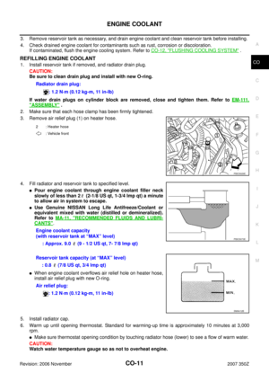
REMOVAL
1. Remove front timing chain case. Refer to EM-44, "FRONT TIMING CHAIN CASE" .
2. Remove timing chain tensioner (primary) as follows:
a. Remove lower mounting bolt (1).
b. Loosen upper mounting bolt (2) slowly, and then turn chain ten-
sioner (primary) (3) on the upper mounting bolt so that plunger
(4) is fully expanded.
NOTE:
Even if plunger is fully expanded, it is not dropped from the body
of timing chain tensioner (primary).
c. Remove upper mounting bolt, and then remove timing chain tensioner (primary).
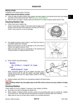
3. Remove water pump as follows:
a. Remove three water pump mounting bolts. Secure a gap between water pump gear and timing chain, by
turning crankshaft counterclockwise until timing chain looseness on water pump sprocket becomes maxi-
mum.
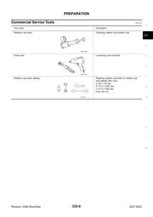
1. Timing chain tensioner (primary) 2. Water pump 3. O-ring
4. O- ring
A. Identify with yellow paint mark B.Identify with light blue paint mark
Apply engine coolant
PBIC5030E
PBIC4938E
Page 24 of 30
![NISSAN 350Z 2007 Z33 Engine Cooling System Workshop Manual CO-24
WATER PUMP
Revision: 2006 November2007 350Z
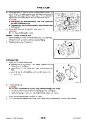
b. Screw M8 bolts (A) [pitch: 1.25 mm (0.049 in) length: approx. 50
mm (1.97 in)] into water pumps upper and lower mounting bolt
holes until they reac](/manual-img/5/763/w960_763-23.png "NISSAN 350Z 2007 Z33 Engine Cooling System Workshop Manual CO-24
WATER PUMP
Revision: 2006 November2007 350Z
b. Screw M8 bolts (A) [pitch: 1.25 mm (0.049 in) length: approx. 50
mm (1.97 in)] into water pumps upper and lower mounting bolt
holes until they reac")
CO-24
WATER PUMP
Revision: 2006 November2007 350Z
b. Screw M8 bolts (A) [pitch: 1.25 mm (0.049 in) length: approx. 50
mm (1.97 in)] into water pumps upper and lower mounting bolt
holes until they reach timing chain case. Then, alternately
tighten each bolt for a half turn, and pull out water pump (1).
CAUTION:
�Pull straight out while preventing vane from contacting
socket in installation area.
�Remove water pump without causing sprocket to contact
timing chain.
c. Remove M8 bolts and O-rings from water pump (1).
CAUTION:
Do not disassemble water pump.
INSPECTION AFTER REMOVAL
�Check for badly rusted or corroded water pump body assembly.
�Check for rough operation due to excessive end play.
�Replace water pump, if necessary.
INSTALLATION
1. Install new O-rings to water pump.
�Apply engine oil to O-rings (1) and engine coolant to O-ring
(3) as shown in the figure.
�Locate O-ring (1) with yellow paint mark (A) to engine front
side.
�Locate O-ring (3) with light blue paint mark (B) to rear side.
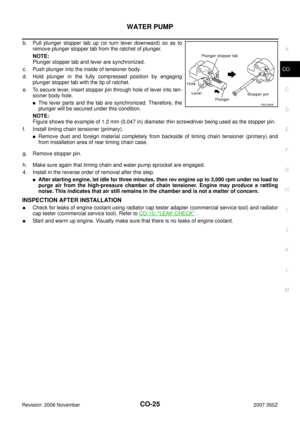
2. Install water pump.
CAUTION:
Do not allow cylinder block to nip O-rings when installing water pump.
�Make sure that timing chain and water pump sprocket are engaged.
�Insert water pump by tightening mounting bolts alternately and evenly.
3. Install timing chain tensioner (primary) as follows:
a. Turn crankshaft clockwise so that timing chain on the timing chain tensioner (primary) side is loose.
PBIC4939E
SLC943A
2 : Water pump
PBIC5074E


CO-19
C
D
E
F
G
H
I
J
K
L
MA
CO
Revision: 2006 November2007 350Z
2. Install sealing rubber while pushing it with fingers.
CAUTION:
Be careful not to twist sealing rubber.
3. C")
 from fan motors.
2. Remove fan motors from fan shroud.
INSPECTION AF")