Page 22 of 312
AT-22
A/T CONTROL SYSTEM
Revision: 2006 November2007 350Z
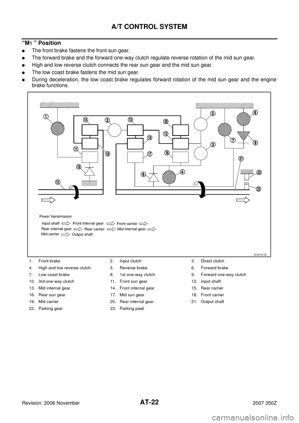
“M1 ” Position
�The front brake fastens the front sun gear.
�The forward brake and the forward one-way clutch regulate reverse rotation of the mid sun gear.
�High and low reverse clutch connects the rear sun gear and the mid sun gear.
�The low coast brake fastens the mid sun gear.
�During deceleration, the low coast brake regulates forward rotation of the mid sun gear and the engine
brake functions.
1. Front brake 2. Input clutch 3. Direct clutch
4. High and low reverse clutch 5. Reverse brake 6. Forward brake
7. Low coast brake 8. 1st one-way clutch 9. Forward one-way clutch
10. 3rd one-way clutch 11. Front sun gear 12. Input shaft
13. Mid internal gear 14. Front internal gear 15. Rear carrier
16. Rear sun gear 17. Mid sun gear 18. Front carrier
19. Mid carrier 20. Rear internal gear 21. Output shaft
22. Parking gear 23. Parking pawl
SCIA1513E
Page 23 of 312
A/T CONTROL SYSTEM
AT-23
D
E
F
G
H
I
J
K
L
MA
B
AT
Revision: 2006 November2007 350Z
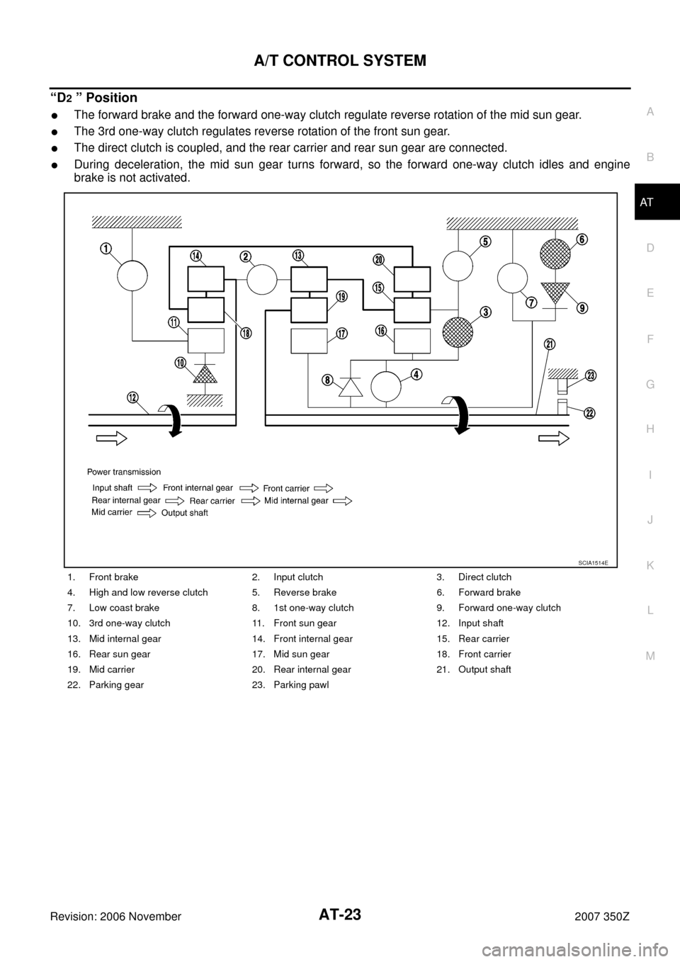
“D2 ” Position
�The forward brake and the forward one-way clutch regulate reverse rotation of the mid sun gear.
�The 3rd one-way clutch regulates reverse rotation of the front sun gear.
�The direct clutch is coupled, and the rear carrier and rear sun gear are connected.
�During deceleration, the mid sun gear turns forward, so the forward one-way clutch idles and engine
brake is not activated.
1. Front brake 2. Input clutch 3. Direct clutch
4. High and low reverse clutch 5. Reverse brake 6. Forward brake
7. Low coast brake 8. 1st one-way clutch 9. Forward one-way clutch
10. 3rd one-way clutch 11. Front sun gear 12. Input shaft
13. Mid internal gear 14. Front internal gear 15. Rear carrier
16. Rear sun gear 17. Mid sun gear 18. Front carrier
19. Mid carrier 20. Rear internal gear 21. Output shaft
22. Parking gear 23. Parking pawl
SCIA1514E
Page 24 of 312
AT-24
A/T CONTROL SYSTEM
Revision: 2006 November2007 350Z
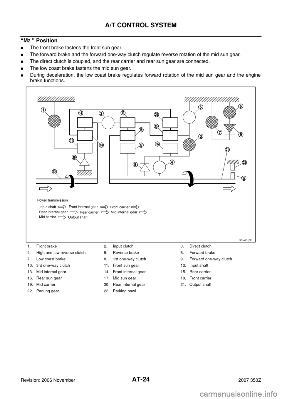
“M2 ” Position
�The front brake fastens the front sun gear.
�The forward brake and the forward one-way clutch regulate reverse rotation of the mid sun gear.
�The direct clutch is coupled, and the rear carrier and rear sun gear are connected.
�The low coast brake fastens the mid sun gear.
�During deceleration, the low coast brake regulates forward rotation of the mid sun gear and the engine
brake functions.
1. Front brake 2. Input clutch 3. Direct clutch
4. High and low reverse clutch 5. Reverse brake 6. Forward brake
7. Low coast brake 8. 1st one-way clutch 9. Forward one-way clutch
10. 3rd one-way clutch 11. Front sun gear 12. Input shaft
13. Mid internal gear 14. Front internal gear 15. Rear carrier
16. Rear sun gear 17. Mid sun gear 18. Front carrier
19. Mid carrier 20. Rear internal gear 21. Output shaft
22. Parking gear 23. Parking pawl
SCIA1515E
Page 29 of 312

A/T CONTROL SYSTEM
AT-29
D
E
F
G
H
I
J
K
L
MA
B
AT
Revision: 2006 November2007 350Z
TCM FunctionNCS0001M
The function of the TCM is to:
�Receive input signals sent from various switches and sensors.
�Determine required line pressure, shifting point, lock-up operation, and engine brake operation.
�Send required output signals to the respective solenoids.
CONTROL SYSTEM OUTLINE
The A/T senses vehicle operating conditions through various sensors or signals. It always controls the opti-
mum shift position and reduces shifting and lock-up shocks.
CONTROL SYSTEM DIAGRAM
SENSORS (or SIGNALS)
�TCM
�ACTUATORS
PNP switch
Accelerator pedal position signal
Closed throttle position signal
Wide open throttle position signal
Engine speed signal
A/T fluid temperature sensor
Revolution sensor
Vehicle speed signal
Manual mode switch signal
Stop lamp switch signal
Turbine revolution sensor
ATF pressure switchShift control
Line pressure control
Lock-up control
Engine brake control
Timing control
Fail-safe control
Self-diagnosis
CONSULT-III communication line
Duet-EA control
CAN systemInput clutch solenoid valve
Direct clutch solenoid valve
Front brake solenoid valve
High and low reverse clutch
solenoid valve
Low coast brake solenoid valve
Torque converter clutch sole-
noid valve
Line pressure solenoid valve
A/T CHECK indicator lamp
Starter relay
Back-up lamp relay
SCIA8327E
Page 30 of 312
 is a serial communication line for real time application. It is an")
AT-30
A/T CONTROL SYSTEM
Revision: 2006 November2007 350Z
CAN CommunicationNCS0001N
SYSTEM DESCRIPTION
CAN (Controller Area Network) is a serial communication line for real time application. It is an on-vehicle mul-
tiplex communication line with high data communication speed and excellent error detection ability. Many elec-
tronic control units are equipped onto a vehicle, and each control unit shares information and links with other
control units during operation (not independent). In CAN communication, control units are connected with 2
communication lines (CAN-H line, CAN-L line) allowing a high rate of information transmission with less wiring.
Each control unit transmits/receives data but selectively reads required data only. For details, refer to LAN-48,
"CAN System Specification Chart" .
Input/Output Signal of TCMNCS0001O
�*1: Spare for vehicle speed sensor A/T (revolution sensor)
�*2: Spare for accelerator pedal position signal
�*3: If these input and output signals are different, the TCM triggers the fail-safe function.
�*4: Used as a condition for starting self-diagnostics; if self-diagnostics are not started, it is judged that there is some kind of error.
�*5: Input by CAN communications
�*6: Output by CAN communicationsControl itemLine
pressure
controlVehicle
speed
controlShift
controlLock-up
controlEngine
brake
controlFail-safe
function
(*3)
Self-diag-
nostics
function
InputAccelerator pedal position signal
(*5)XXXXX X X
Vehicle speed sensor A/T
(revolution sensor)XXXXX X X
Vehicle speed sensor MTR
(*1)(*5)X
Closed throttle position signal
(*5)X(*2)XX X
X(*4)
Wide open throttle position signal(*5)X
X(*4)
Turbine revolution sensor 1 X X X X X
Turbine revolution sensor 2
(for 4th speed only)XXXXX
Engine speed signals
(*5)XXXXX X X
Stop lamp switch signal
(*5)XXX
X(*4)
A/T fluid temperature sensors 1, 2 X X X X X X
ASCDOperation signal
(*5)XXX
Overdrive cancel sig-
nal
(*5)X
OutputDirect clutch solenoid X X X X
Input clutch solenoid X X X X
High and low reverse clutch solenoid X X X X
Front brake solenoid X X X X
Low coast brake solenoid
(ATF pressure switch 2)XX X X X
Line pressure solenoid X X X X X X X
TCC solenoid X X X
Self-diagnostics table
(*6)X
Starter relayXX
Page 31 of 312

A/T CONTROL SYSTEM
AT-31
D
E
F
G
H
I
J
K
L
MA
B
AT
Revision: 2006 November2007 350Z
Line Pressure ControlNCS0001P
�When an input torque signal equivalent to the engine drive force is sent from the ECM to the TCM, the
TCM controls the line pressure solenoid.
�This line pressure solenoid controls the pressure regulator valve as the signal pressure and adjusts the
pressure of the operating oil discharged from the oil pump to the line pressure most appropriate to the
driving state.
LINE PRESSURE CONTROL IS BASED ON THE TCM LINE PRESSURE CHARACTERISTIC
PATTERN
�The TCM has stored in memory a number of patterns for the optimum line pressure characteristic for the
driving state.
�In order to obtain the most appropriate line pressure characteristic to meet the current driving state, the
TCM controls the line pressure solenoid current valve and thus controls the line pressure.
Normal Control
Each clutch is adjusted to the necessary pressure to match the
engine drive force.
Back-up Control (Engine Brake)
When the select operation is performed during driving and the A/T is
shifted down, the line pressure is set according to the vehicle speed.
PCIA0007E
PCIA0008E
PCIA0009E
Page 32 of 312
AT-32
A/T CONTROL SYSTEM
Revision: 2006 November2007 350Z
During Shift Change
The necessary and adequate line pressure for shift change is set.
For this reason, line pressure pattern setting corresponds to input
torque and gearshift selection. Also, line pressure characteristic is
set according to engine speed, during engine brake operation.
At Low Fluid Temperature
When the A/T fluid temperature drops below the prescribed tempera-
ture, in order to speed up the action of each friction element, the line
pressure is set higher than the normal line pressure characteristic.
Shift ControlNCS0001Q
The clutch pressure control solenoid is controlled by the signals from the switches and sensors. Thus, the
clutch pressure is adjusted to be appropriate to the engine load state and vehicle driving state. It becomes
possible to finely control the clutch hydraulic pressure with high precision and a smoother shift change charac-
teristic is attained.
PCIA0010E
PCIA0011E
PCIA0012E
Page 33 of 312

A/T CONTROL SYSTEM
AT-33
D
E
F
G
H
I
J
K
L
MA
B
AT
Revision: 2006 November2007 350Z
NORMAL SHIFT CONTROL
The clutch is controlled with the optimum timing and oil pressure by the engine speed, engine torque informa-
tion, etc.
Shift Change System Diagram
*1: Full phase real-time feedback control monitors movement of gear ratio at gear change, and controls oil
pressure at real-time to achieve the best gear ratio.
BLIPPING CONTROL
This system makes transmission clutch engage readily by controlling (synchronizing) engine revolution
according to the (calculation of) engine revolution after shifting down.
�“BLIPPING CONTROL” functions.
–When downshifting by accelerator pedal depression at “D” position.
–When downshifting under the manual mode.
�TCM selects “BLIPPING CONTROL” or “NORMAL SHIFT CONTROL” according to the gear position, the
select lever position, the engine torque and the speed when accelerating by pedal depression.
�Revolution control demand signal is transmitted from TCM to ECM under “BLIPPING CONTROL”.
�TCM synchronizes engine revolution according to the revolution control demand signal.
PCIA0013E