Page 51 of 142
TROUBLE DIAGNOSIS
ATC-51
C
D
E
F
G
H
I
K
L
MA
B
AT C
Revision: 2006 November2007 350Z
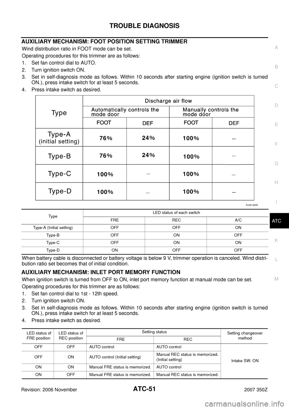
AUXILIARY MECHANISM: FOOT POSITION SETTING TRIMMER
Wind distribution ratio in FOOT mode can be set.
Operating procedures for this trimmer are as follows:
1. Set fan control dial to AUTO.
2. Turn ignition switch ON.
3. Set in self-diagnosis mode as follows. Within 10 seconds after starting engine (ignition switch is turned
ON.), press intake switch for at least 5 seconds.
4. Press intake switch as desired.
When battery cable is disconnected or battery voltage is below 9 V, trimmer operation is canceled. Wind distri-
bution ratio set becomes that of initial condition.
AUXILIARY MECHANISM: INLET PORT MEMORY FUNCTION
When ignition switch is turned from OFF to ON, inlet port memory function at manual mode can be set.
Operating procedures for this trimmer are as follows:
1. Set fan control dial to 1st - 12th speed.
2. Turn ignition switch ON.
3. Set in self-diagnosis mode as follows. Within 10 seconds after starting engine (ignition switch is turned
ON.), press intake switch for at least 5 seconds.
4. Press intake switch as desired.
RJIA1365E
Ty p eLED status of each switch
FRE REC A/C
Type-A (Initial setting) OFF OFF ON
Ty p e - B O F F O N O F F
Type-C OFF ON ON
Type-D ON OFF OFF
LED status of
FRE positionLED status of
REC positionSetting status
Setting changeover
method
FRE REC
OFF OFF AUTO control AUTO control
Intake SW: ON OFF ON AUTO control (Initial setting)Manual REC status is memorized.
(Initial setting)
ON ON Manual FRE status is memorized. AUTO control
ON OFF Manual FRE status is memorized. Manual REC status is memorized.
Page 52 of 142
ATC-52
TROUBLE DIAGNOSIS
Revision: 2006 November2007 350Z
When battery cable is disconnected or battery voltage is below 9 V, memory function is canceled. Memory
function set becomes that of initial condition.
Page 55 of 142
TROUBLE DIAGNOSIS
ATC-55
C
D
E
F
G
H
I
K
L
MA
B
AT C
Revision: 2006 November2007 350Z
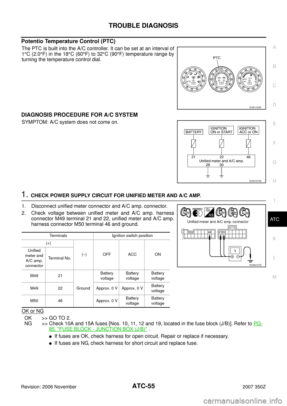
Potentio Temperature Control (PTC)
The PTC is built into the A/C controller. It can be set at an interval of
1°C (2.0°F) in the 18°C (60°F) to 32°C (90°F) temperature range by
turning the temperature control dial.
DIAGNOSIS PROCEDURE FOR A/C SYSTEM
SYMPTOM: A/C system does not come on.
1. CHECK POWER SUPPLY CIRCUIT FOR UNIFIED METER AND A/C AMP.
1. Disconnect unified meter connector and A/C amp. connector.
2. Check voltage between unified meter and A/C amp. harness
connector M49 terminal 21 and 22, unified meter and A/C amp.
harness connector M50 terminal 46 and ground.
OK or NG
OK >> GO TO 2.
NG >> Check 10A and 15A fuses [Nos. 10, 11, 12 and 19, located in the fuse block (J/B)]. Refer to PG-
85, "FUSE BLOCK - JUNCTION BOX (J/B)" .
�If fuses are OK, check harness for open circuit. Repair or replace if necessary.
�If fuses are NG, check harness for short circuit and replace fuse.
SJIA1124E
RJIA1374E
Terminals Ignition switch position
(+)
(−)OFF ACC ON Unified
meter and
A/C amp.
connectorTerminal No.
M49 21
GroundBattery
voltageBattery
voltageBattery
voltage
M49 22 Approx. 0 V Approx. 0 VBattery
voltage
M50 46 Approx. 0 VBattery
voltageBattery
voltage
RJIA2121E
Page 56 of 142
ATC-56
TROUBLE DIAGNOSIS
Revision: 2006 November2007 350Z
2. CHECK GROUND CIRCUIT FOR UNIFIED METER AND A/C AMP.
1. Turn ignition switch OFF.
2. Check continuity between unified meter and A/C amp. harness
connector M49 terminal 29, 30 and ground.
OK or NG
OK >> Replace unified meter and A/C amp.
NG >> Repair harness or connector.
LAN System CircuitNJS0000Z
SYMPTOM: Mode door motor, intake door motor and/or air mix door motor does not operate normally.
DIAGNOSIS PROCEDURE FOR LAN CIRCUIT
1. CHECK POWER SUPPLY FOR UNIFIED METER AND A/C AMP.
1. Turn ignition switch ON.
2. Check voltage between unified meter and A/C amp. harness
connector M50 terminal 54 and ground.
OK or NG
OK >> GO TO 2.
NG >> Replace unified meter and A/C amp.29, 30 – Ground : Continuity should exist.
RJIA1985E
RJIA2122E
54 – Ground : Battery voltage
RJIA1986E
Page 57 of 142
TROUBLE DIAGNOSIS
ATC-57
C
D
E
F
G
H
I
K
L
MA
B
AT C
Revision: 2006 November2007 350Z
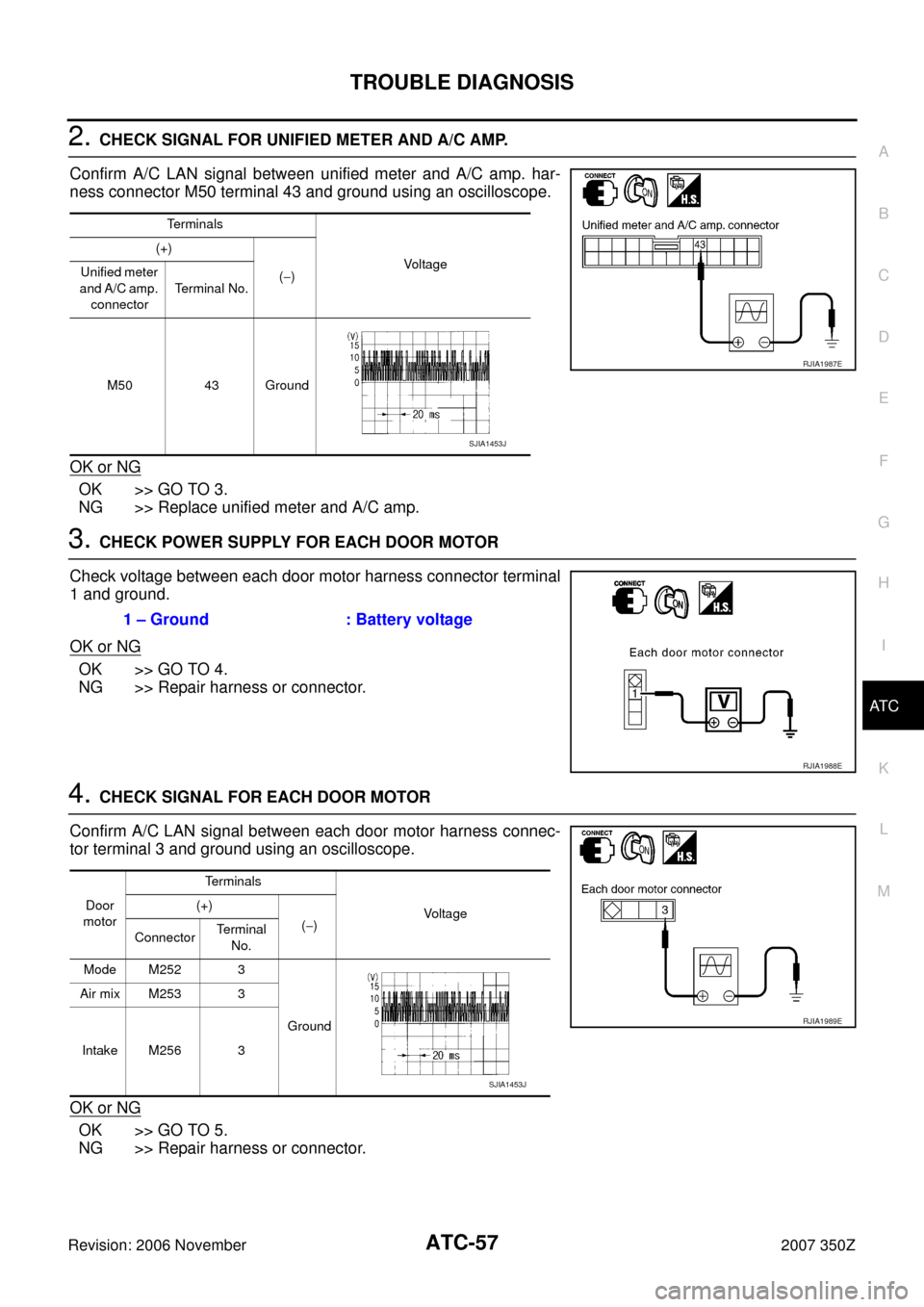
2. CHECK SIGNAL FOR UNIFIED METER AND A/C AMP.
Confirm A/C LAN signal between unified meter and A/C amp. har-
ness connector M50 terminal 43 and ground using an oscilloscope.
OK or NG
OK >> GO TO 3.
NG >> Replace unified meter and A/C amp.
3. CHECK POWER SUPPLY FOR EACH DOOR MOTOR
Check voltage between each door motor harness connector terminal
1 and ground.
OK or NG
OK >> GO TO 4.
NG >> Repair harness or connector.
4. CHECK SIGNAL FOR EACH DOOR MOTOR
Confirm A/C LAN signal between each door motor harness connec-
tor terminal 3 and ground using an oscilloscope.
OK or NG
OK >> GO TO 5.
NG >> Repair harness or connector.
Te r m i n a l s
Vo l ta g e (+)
(−) Unified meter
and A/C amp.
connectorTerminal No.
M50 43 Ground
RJIA1987E
SJIA1453J
1 – Ground : Battery voltage
RJIA1988E
Door
motorTerminals
Vo l ta g e (+)
(−)
ConnectorTerminal
No.
Mode M252 3
Ground Air mix M253 3
Intake M256 3
RJIA1989E
SJIA1453J
Page 72 of 142
ATC-72
TROUBLE DIAGNOSIS
Revision: 2006 November2007 350Z
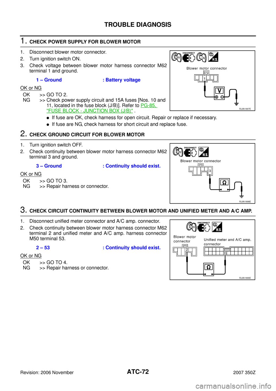
1. CHECK POWER SUPPLY FOR BLOWER MOTOR
1. Disconnect blower motor connector.
2. Turn ignition switch ON.
3. Check voltage between blower motor harness connector M62
terminal 1 and ground.
OK or NG
OK >> GO TO 2.
NG >> Check power supply circuit and 15A fuses [Nos. 10 and
11, located in the fuse block (J/B)]. Refer to PG-85,
"FUSE BLOCK - JUNCTION BOX (J/B)" .
�If fuse are OK, check harness for open circuit. Repair or replace if necessary.
�If fuse are NG, check harness for short circuit and replace fuse.
2. CHECK GROUND CIRCUIT FOR BLOWER MOTOR
1. Turn ignition switch OFF.
2. Check continuity between blower motor harness connector M62
terminal 3 and ground.
OK or NG
OK >> GO TO 3.
NG >> Repair harness or connector.
3. CHECK CIRCUIT CONTINUITY BETWEEN BLOWER MOTOR AND UNIFIED METER AND A/C AMP.
1. Disconnect unified meter connector and A/C amp. connector.
2. Check continuity between blower motor harness connector M62
terminal 2 and unified meter and A/C amp. harness connector
M50 terminal 53.
OK or NG
OK >> GO TO 4.
NG >> Repair harness or connector.1 – Ground : Battery voltage
RJIA1997E
3 – Ground : Continuity should exist.
RJIA1998E
2 – 53 : Continuity should exist.
RJIA1999E
Page 76 of 142
ATC-76
TROUBLE DIAGNOSIS
Revision: 2006 November2007 350Z
1. CHECK AMBIENT SENSOR CIRCUIT AND INTAKE SENSOR CIRCUIT
Check ambient sensor and intake sensor. Refer to AT C - 4 6 , "
FUNCTION CONFIRMATION PROCEDURE" ,
see No. 9.
OK or NG
OK >> GO TO 2.
NG >>
�Malfunctioning ambient sensor: Refer to AT C - 9 2 , "Ambient Sensor Circuit" .
�Malfunctioning intake sensor: Refer to ATC-100, "Intake Sensor Circuit" .
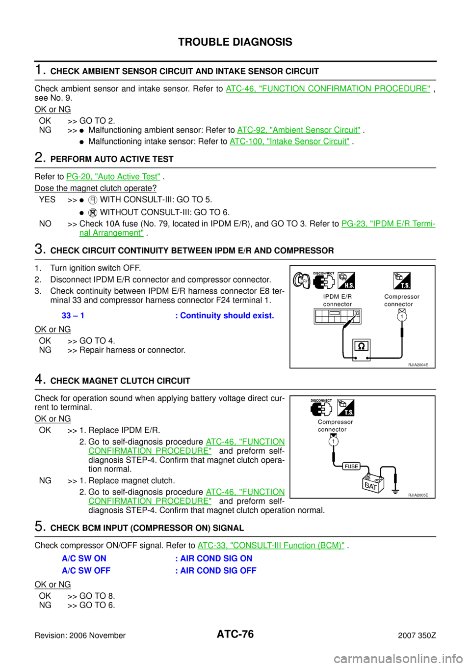
2. PERFORM AUTO ACTIVE TEST
Refer to PG-20, "
Auto Active Test" .
Dose the magnet clutch operate?
YES >>� WITH CONSULT-III: GO TO 5.
� WITHOUT CONSULT-III: GO TO 6.
NO >> Check 10A fuse (No. 79, located in IPDM E/R), and GO TO 3. Refer to PG-23, "
IPDM E/R Termi-
nal Arrangement" .
3. CHECK CIRCUIT CONTINUITY BETWEEN IPDM E/R AND COMPRESSOR
1. Turn ignition switch OFF.
2. Disconnect IPDM E/R connector and compressor connector.
3. Check continuity between IPDM E/R harness connector E8 ter-
minal 33 and compressor harness connector F24 terminal 1.
OK or NG
OK >> GO TO 4.
NG >> Repair harness or connector.
4. CHECK MAGNET CLUTCH CIRCUIT
Check for operation sound when applying battery voltage direct cur-
rent to terminal.
OK or NG
OK >> 1. Replace IPDM E/R.
2. Go to self-diagnosis procedure AT C - 4 6 , "
FUNCTION
CONFIRMATION PROCEDURE" and preform self-
diagnosis STEP-4. Confirm that magnet clutch opera-
tion normal.
NG >> 1. Replace magnet clutch.
2. Go to self-diagnosis procedure AT C - 4 6 , "
FUNCTION
CONFIRMATION PROCEDURE" and preform self-
diagnosis STEP-4. Confirm that magnet clutch operation normal.
5. CHECK BCM INPUT (COMPRESSOR ON) SIGNAL
Check compressor ON/OFF signal. Refer to AT C - 3 3 , "
CONSULT-III Function (BCM)" .
OK or NG
OK >> GO TO 8.
NG >> GO TO 6.
33 – 1 : Continuity should exist.
RJIA2004E
RJIA2005E
A/C SW ON : AIR COND SIG ON
A/C SW OFF : AIR COND SIG OFF
Page 117 of 142
AIR MIX DOOR MOTOR
ATC-117
C
D
E
F
G
H
I
K
L
MA
B
AT C
Revision: 2006 November2007 350Z
AIR MIX DOOR MOTORPFP:27732
Removal and InstallationNJS0001R
REMOVAL
1. Set the temperature control dial at 18°C (60°F).
2. Open the driver and front passenger window, and then disconnect the battery cable from the negative ter-
minal.
CAUTION:
After the battery cables are disconnected, do not open/close the driver and/or front passenger
door with the window in the full up position. The automatic window adjusting function will not
work and the side roof panel may be damaged.
3. Remove blower unit. Refer to ATC-108, "
BLOWER UNIT" .
4. Disconnect air mix door motor connector.
5. Remove mounting screws, and then remove air mix door motor.
INSTALLATION
Installation is basically the reverse order of removal.
SJIA1175E